logo elektroda
logo elektroda
X
logo elektroda

Powering the Wemos D1 Mini with the HLK-PM0x. Which is more advantageous?

mtbchn 567 3
ADVERTISEMENT
Treść została przetłumaczona polish » english Zobacz oryginalną wersję tematu
  • #1 20799800
    mtbchn
    Level 3  
    Hi,

    I will be powering the Wemos D1 Mini board from the HLK-PM0x power supply. The ESP8266 will control some mosfets and a triac. I'm wondering which is more advantageous:

    1) Powering the Wemos D1 Mini with the HLK-PM01 (5 VDC) and thereby stabilising the voltage on the ESP8266 with the Wemos board's built-in stabiliser.

    2) Powering the Wemos D1 Mini using HLK-PM03 (3.3 VDC) and omitting the stabiliser on the Wemos D1 Mini board.


    Of course, I assume that in both cases I add a pair of filter capacitors at the input.


    What is your opinion on this topic? Thanks in advance for your response.
  • ADVERTISEMENT
  • #2 20799817
    khoam
    Level 42  
    mtbchn wrote:
    I wonder which is preferable
    The latter. The 3V3 stabiliser on this board (usually ME6211) won't give much current, and its cooling is poor.

    mtbchn wrote:
    Of course I assume that in both cases I'm adding a pair of filter capacitors at the input.
    If any more, it's ceramic, against interference. Adding electrolytic capacitors is pointless.
  • ADVERTISEMENT
  • #3 20799956
    mtbchn
    Level 3  
    khoam wrote:
    mtbchn wrote:
    I am wondering which is preferable

    The latter. The 3V3 stabiliser on this board (usually ME6211) does not give much current, and its cooling is poor.

    Thanks for the specific answer.

    mtbchn wrote:
    Of course, I assume that in both cases I add a pair of filter capacitors at the input.

    If I do, it's ceramic, against interference. Adding electrolytic capacitors is pointless.


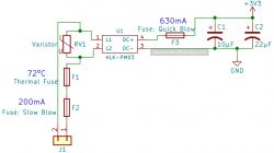
    Can you elaborate on the omission of electrolytic capacitors? I was planning to use a pair of 220 uF and 100 nF at the HLK-PM output. I took the following application diagram as a reference:

    Connection diagram with fuse, varistor, capacitor, inductor, and power module

    And one more question. If I had a bare ESP8266, I would use at least one 100 nF capacitor as close as possible to the uC power supply leg. Here I have a D1 Mini board available, so is there therefore any point in adding this capacitor at the 3.3 V goldpin of the Wemos?
  • #4 20799990
    khoam
    Level 42  
    You can give electrolytic capacitors at the output, but small capacitance 10-22 µF.

    mtbchn wrote:
    I have a D1 Mini board available here, so is there therefore any point in adding this capacitor at the 3.3 V goldpin of the Wemos?

    On the 3V3 line of the D1 Mini there is an electrolytic capacitor of 1-10 µF depending on the board version. If there are interference problems on the supply line, then a 100 nF ceramic can be added. It all depends on whether and which peripherals you will connect to this board.

    Electrical schematic with HLK-PM03 module and capacitors.

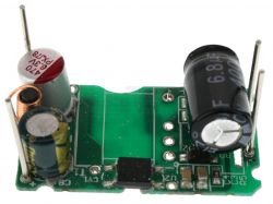
    In the HLK-PM03 module, there are already electrolytic capacitors on its race. In my opinion, this is completely sufficient. I use such modules (in the version without housing) and I have not noticed the need to install additional electrolytic capacitors.

    Electronic module with two electrolytic capacitors on a green circuit board.
ADVERTISEMENT