
Atmega fusebit doctor, as the name says, is a device for repairing mismatched fusebits in microcontrollers from the AVR family. The biggest problems are setting the wrong clock source (CKSEL fusebits), disabling SPI programming (SPIEN fusebit), or setting the reset pin to I / O mode (RSTDISBL fusebit). This simple device will repair the microcontroller by giving it factory settings in a fraction of a second.
While in the first case you can use a clock generator or an RC / quartz generator, in the second and third case, it is not possible to bring the microcontroller back to life using the SPI serial programmer. Few people decide to build a parallel programmer, because it is inconvenient to use, and because it is cheaper to buy a new microcontroller than to play some repairs.
The presented device uses the possibility of parallel (and serial programming from version 2.03) high voltage. The device is extremely simple and cheap to build, you only need ATmega8 as a doctor, two LEDs, a jumper, a stabilizer, transistors. Signatures of 96 AVR microcontrollers and their factory fusebits are saved in the memory, just insert the "released" uC into the socket and press the button
START and the system will perform the required operation and our patient will be brought back to life. The entire procedure takes a fraction of a second.
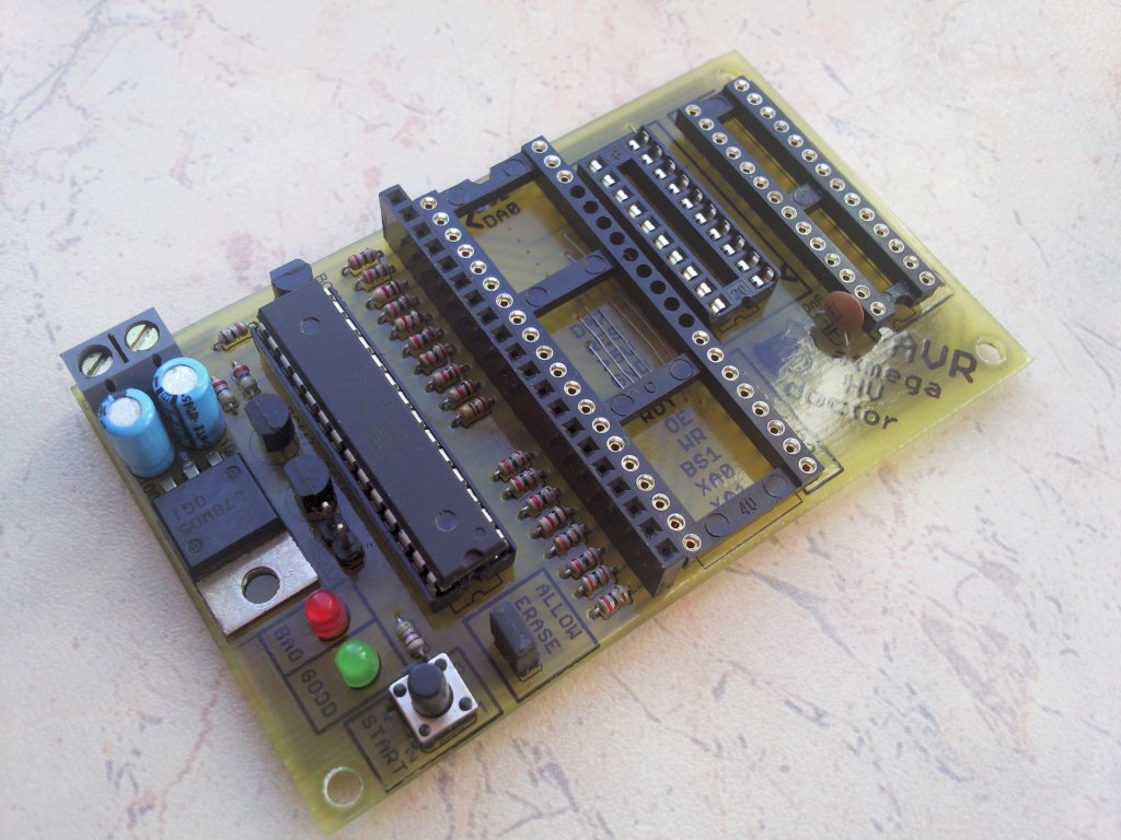
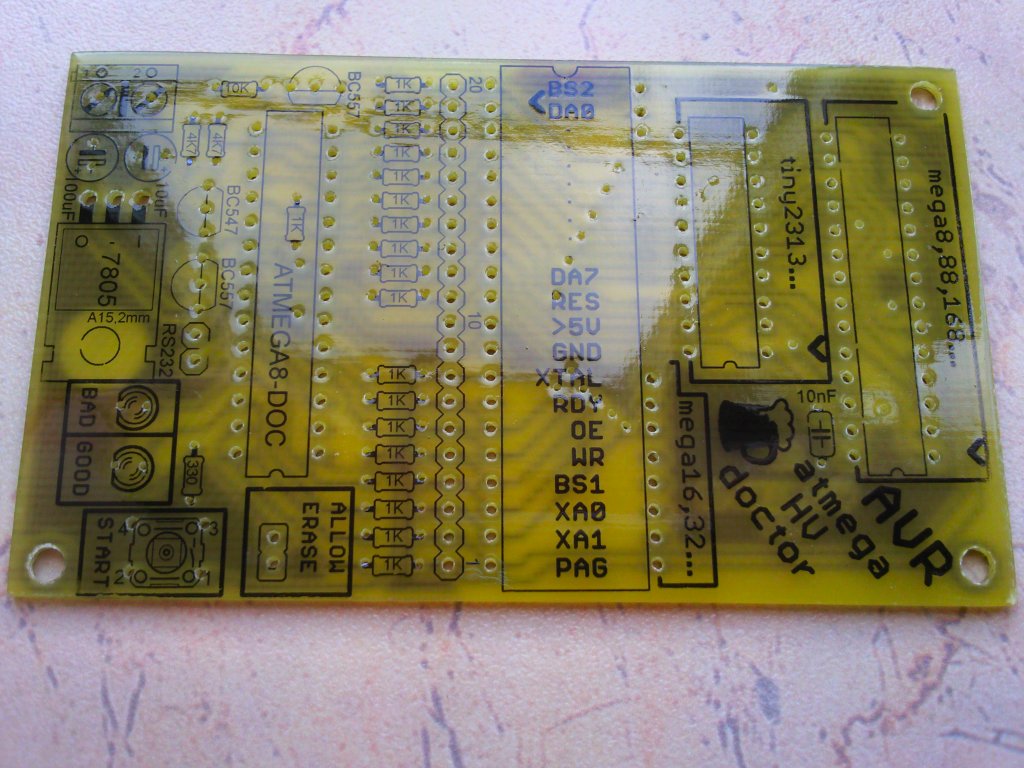
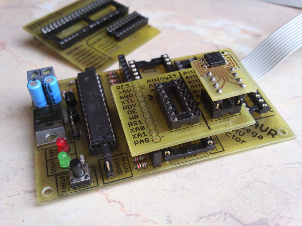
There are three sockets on the main board for processors that are pin compatible with atmega8, atmega16, and attiny2313, i.e. the most popular ones. In addition, the board has a female goldpin connector with all necessary signals led out, for connecting adapters:
"
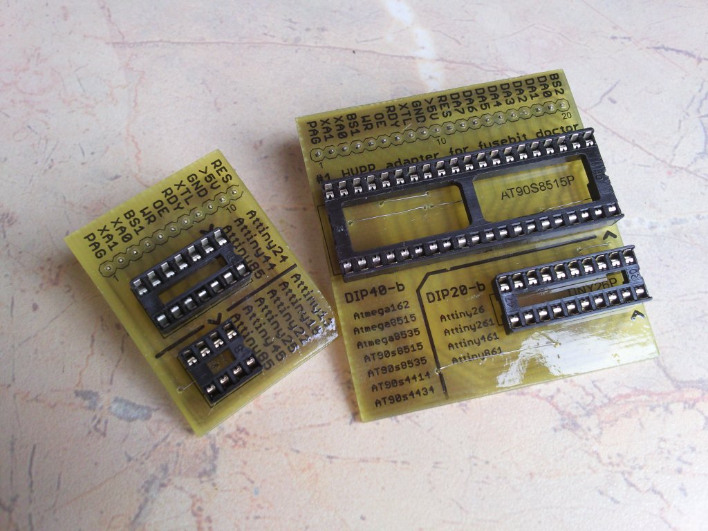
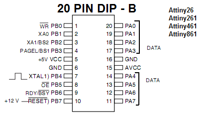
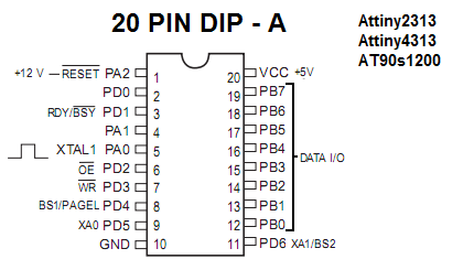
# 1 HVPP adapter "As an HVPP extension for 20pin Attiny26 and 40pin Atmega8515 compatible processors
"
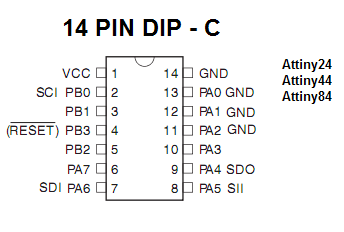
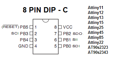
HVSP adapter "For HVSP 8pin and 14 pin attiny processors, which cannot be programmed in parallel due to too few pins.
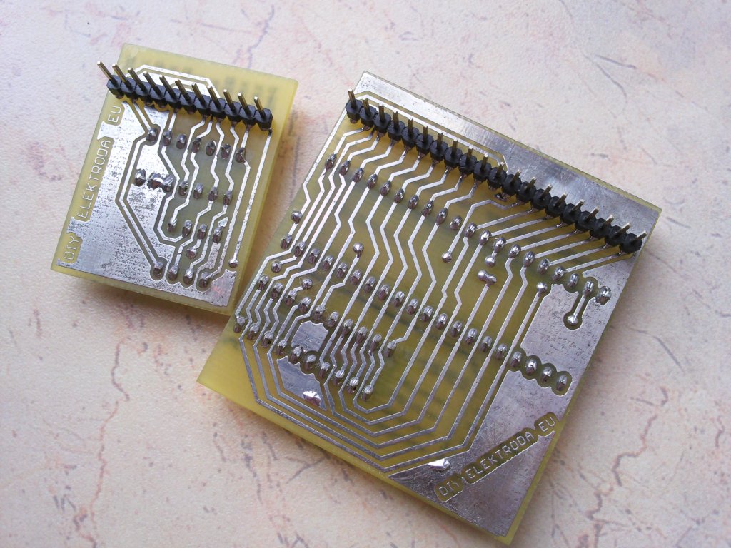
It is possible to make your own additional adapters for other types of processors in DIP or SMD casings. However, you do not need to make an adapter to repair one chip, you can do it with a contact plate by connecting the signals to the appropriate pins. As? Check the datasheet of your AVR, go to "memory programming" and then "parallel programming" - the names of the signals and pins as on the tray. All pins are signed under the DIP40 socket, and in the attachment there is also a project of an "empty" adapter.
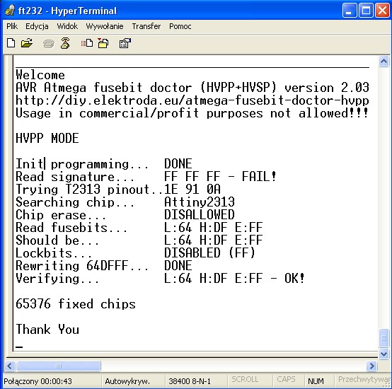
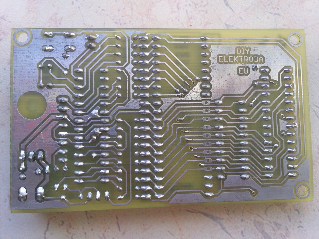
Single-sided plate, 55mm x 92mm. Several jumpers should be soldered on the top part, or the board can also be double-sided. 12V stabilized power supply. Resistors R7 to R23 can have values from 100 ohms to 1K, I suggest rather 330ohm. It should be remembered that the three pins of the bits from the data line are also used by the ISP programmer to update the program - the device will not work properly if, for example, we solder to them with the programmer. The board also has a connector described as RS232, it is a UART output, by connecting to it (38000bps), we will learn everything about the course of the repair operation - an example screenshot below. Of course, the terminal is not necessary, we will find out everything from the diodes themselves

 ATTENTION!
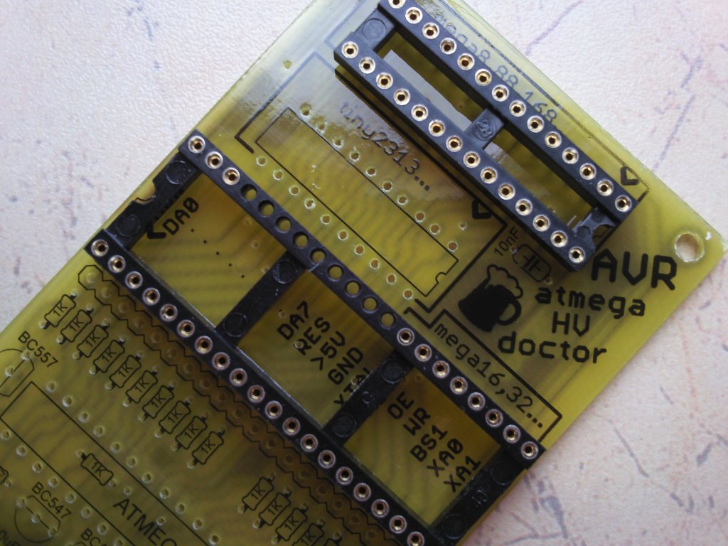
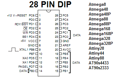
 When installing the DIP40 socket, remove the metal connectors from pin 29 to 37 from it! The paths passing in these places cannot be electrically connected to the pins of the inserted processor, and they run there to simplify the board itself. I have marked which pins in the picture below:
 Diode markings
 :
glows green - fusebits fixed and verified, system fixed. If the lockbit protection is set, it only checks whether the fuses correspond to the factory ones, and if so, it will also light this diode.
shines red - problem with reading the signature, no system or no signature in the database.
blinking green - signature read, fusebits do not match the factory ones, but lockbits are set and you need to allow memory wiping to fix them (read on).
flashing red - signature read, lockbits disabled, but new fusebits cannot be saved for some reason.
Jumper
ALLOW ERASE allows you to erase the entire memory in the case of set Lockbits (without deleting them, it is not possible to change the Fusebits). After connecting the system and pressing the START button, the program initiates the parallel programming mode, or if an HVSP adapter is used - initiates the serial programming mode. The patient responds with a high status on the RDY / BSY pin. The first thing the doctor does is wipe all memory if allowed by the user. After that, it reads the signature of the connected microcontroller and checks if it is able to handle it. Then the lockbits are checked, and if they do not block access, the doctor reads the fusebits and compares them with the factory ones stored in the database. If they differ, it saves the factory settings, taking into account whether the given patient model has extended fusebits or not. There are also processors with only one fusebit byte and that is also included. At the end, the program verifies their correctness and lights the appropriate LED. Information via rs232 is sent on a regular basis.
The program was written on the basis of the description of parallel (and serial) programming contained in most AVR microcontroller catalog notices, (memory programming - parallel / serial programming).
The project started in 2008, but abandoned due to lack of time, now redone.
Fusebits: Internal 8MHz clock, and EESAVE bit on. As it is 2in1 (HVPP and HVSP), the 8kB Atmega8 memory turned out to be insufficient and not all the bells and whistles came in ...
1.Not all processors display names after rs232, but the most popular ones. However, this has no effect on the operation of the system.
2. Some text sent by rs232 has been stored in EEPROM. Even if you are not going to use this output, you MUST program the eeprom with EEP.BIN or EEP.HEX! Using a chip with an unprogrammed or badly programmed eeprom will do more harm than good!
If the green LED is on, you can be 100% sure that the fusebits have been reset. If the chip still does not correspond to the normal ISP programmer, it means that it has a damaged hardware SPI, it has other damage, or you have uploaded the eeprom. If the red LED is flashing, the only thing you can do is check what the doctor is sending via rs232 - then I can help you fix the problem.
Number of processors supported: 96
Number of supported sockets: 53 The rest are SMD cases, there are no adapters for them yet.
Full list of supported processors: (tested marked green)
1kB: AT90s1200, Attiny11, Attiny12,
Attiny13 , Attiny15
2kB: Attiny 2313 , Attiny26, Attiny261, Attiny28, AT90s2333, Attiny22,
Attiny25 , AT90s2323, AT90s2343
4kB: Atmega48, Atmega48P, Attiny461, Attiny43U, Attiny4313, Attiny48, AT90s4433, AT90s4414, AT90s4434,
Attiny45 8kB: Atmega8515,
Atmega8535 ,
Atmega8 ,
Atmega88 , Atmega88P, AT90pwm1, AT90pwm2, AT90pwm2B, AT90pwm3, AT90pwm3B, AT90pwm81, AT90usb82, Attiny861, Attiny88, Attiny85
16kB: Atmega16 , Atmega16U4, Atmega16M1, Atmega161, Atmega162, Atmega163, Atmega164, Atmega164P, Atmega165,
Atmega168 , Atmega168P, Atmega169, AT90pwm216, AT90pwm316, AT90usb162
32kB: Atmega32 , Atmega32U4, Atmega32M1, Atmega324, Atmega324P, Atmega325, Atmega3250, Atmega325P, Atmega3250P, Atmega328, Atmega328P, Atmega329, Atmega3290, AT90can32
64kB: Atmega64, Atmega64M1, Atmega649, Atmega6490, Atmega640, Atmega644, Atmega644P, Atmega645, Atmega6450, AT90usb646, AT90usb647, AT90can64
128kB: Atmega103, Atmega128, Atmega1280, Atmega1281, Atmega1284, Atmega1284P, AT90usb1286, AT90usb1287, AT90can128
256kB: Atmega2560, Atmega2561
Gallery:


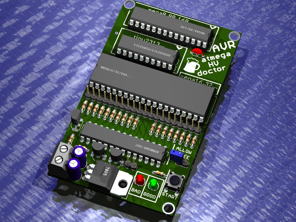
Eagle 3D render:

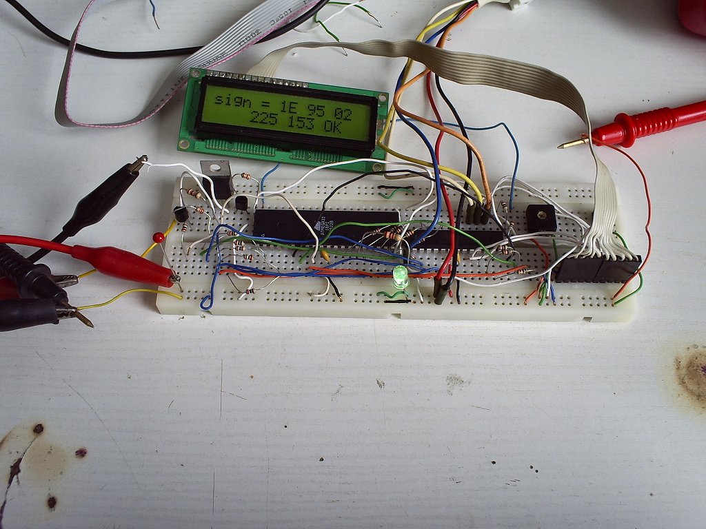
Prototype - Atmega8 reads Atmegi32 signature and fuses with damaged SPI, and displays info on LCD:

Adapters:


 Compatibility with stands - what we put where:


 In the attachment all files:
 Design of the board and adapters (eagle 5.4.0) version 2.0d: BRD, SCH, and printable PDF versions
Object code (bascom 1.11.9.0) version 2.03: HEX and BIN
Eeprom image version 2.03: HEX and BIN
A brief explanation for those not in the topic:
HVPP = high voltage parallel programming = high voltage parallel programming.
HVSP = high voltage serial programming = high voltage serial programming.
So programming methods that allow you to get to the processor despite the disabled reset or isp, i.e. our dead man. Serial programming is used by processors with a small number of pins, because this type requires only a few lines. Parallel programming is used by processors that have at least 20 pins, i.e. everything above tiny2313 inclusive.
The above description and attachment contain all updates,while the full description and all attachments with different hardware and software versions - for the inquisitive - are available on the project website:
http://diy.elektroda.eu/atmega-fusebit-doctor-hvpp/ There are also a lot of comments there, I recommend reading if you have any problems, but here I am also happy to answer if I have time. The system was made by a lot of people, so it is tested and works properly.
_______________________________ NOTE UPDATE # 11 - HERE - -145 supported chips
-sds for Atmega88, Atmega88P, Atmega168, Atmega168P, Atmega328, Atmega328P.
- two-way communication via UART, you can e.g. send your own papers
-dooo much lots of fixed bugs, also on the board
A shortened list of changes and improvements can be found in the changelog, but I recommend reading the whole topic (only 5 pages).
FAQ - frequently asked questions and their answers.
_______________________________ 


Comments
Cool! I just recently dumped 2 ATmegi8 with these fusebits. ;) [Read more]
Nice design, very useful. I have a question about pcbs that are very nicely made? Did you make the layer with the inscriptions and the tile itself with an iron or a laminator? [Read more]
Or maybe the author would convert the main program into some other processor than Atmega8. As you know, it's hard to get at a reasonable price, and there are many other procks in DIP28 housings, with... [Read more]
Can this toy be used to unlock the processor in the TSOP housing - are there any adapter designs ??? [Read more]
I also support the quoted one - especially since I haven't used m8 for a long time and the only one I have now is permanently soldered in the logic analyzer, so I won't use it. But I have 48 (which... [Read more]
Jdsoul, you can make an adapter, but the cost would be enormous (CLIP-type sockets or special top-mounted contact connectors cost a lot, and getting them for ordinary electronics is often close to a miracle).... [Read more]
Well, wouldn't it be better to make a parallel programmer? You will do more with it, because by the way you can program the processor, as you need the reset pin as and / o there is no problem with... [Read more]
well, the most interesting solution, although I don't know if it would work, would be the ISP-> HVPP / HVSP converter I personally would invest in prog. parallel as long as it wasn't on LPT or... [Read more]
Hmm, a used STK500 will probably be cheaper .... [Read more]
How do you do the inscriptions on the tiles? This is a rosin coated toner with a solvent? What? [Read more]
http://diy.elektroda.eu/plytki-drukowane-od-a-do-z/ [Read more]
"cheap"? After all, Atmega8 now costs even PLN 15 [Read more]
Yes, and you will definitely unlock fusebits;] [Read more]
stk500 is an ISP, not an HV EDIT: Incorrect information [Read more]
well the atmeg8 prices are very different: http://www.bujnowicz.com/szukaj/?szukaj=atmega+8&x=0&y=0 in this situation, it is more profitable to buy a larger uP, e.g. mega32 [Read more]
Everyone should realize that the STK500 is prototype board which, in addition to the startup possibilities contains too parallel programmer . You can find a copy of it on the web. Therefore,... [Read more]
ZbeeGin, right, I meant AVR PROG USB partially compatible with stk500. AVR PROG USB only has an ISP. I found atmega32 for the price of 8, also 8 megi does not pay off at all. I still keep asking the... [Read more]
A very nice device. I myself recently "hit" the m8 with a bad clock fuse, but fortunately for me the external RC saved me. A very ingenious device. I have a question: In the description it writes that... [Read more]
lockbits prevent uP reading and programming they are designed to protect the software against unauthorized copying (e.g. you buy a device, copy electronics, download the program and upload it to a new... [Read more]