I have the impression that every electronic engineer at some point in his life constructs a clock and some form of a meter. Time for me with the meter. The project is based on my previous toys using RS458 -
https://www.elektroda.pl/rtvforum/topic3305389.html - uses the same communication protocol as the rest of the toys, thanks to which the gate automatically recognizes them all and does not require any configuration at the network level. Of course, you could buy a ready-made, even more compact one, but once you don't learn anything on this occasion, you can't easily integrate it with the existing network.
The device has four analog channels to measure things. Actually 7, but three are internal, they measure CPU temperature, reference voltage, and supply voltage. The channels are configurable (we have a serial EEPROM), almost entirely SMD, thanks to which (if you omit the RJ45 / power connector module) it is 6x4cm. And since it has different types of connectors, it can always perform one more additional function, the question of writing for this program. There is no schematic of course, as I (almost) usually went to PCB design. Everything done on my recently favorite STM32F030 (C8), cheap, available in china, better features than AVR.
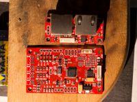
Starting with the connector module and RS485 power supply:
A - Jumpers for connecting the 100Ohm resistor, the bus terminator to the bus.
E - Rj45 connectors from the RS485 bus. The pin layout is ethernet compatible, so you can use exactly the same cabling for both. Maybe someday I will change to eth? In addition, it is simply convenient, you can buy ready-made and cheap cables as needed. The scheme of power pins is the same as in PoE, the voltage is supplied in pairs 3 and 4. Almost the entire network has one power source. One of the connectors has two LEDs, one originally signaled power, the other - transmission. Currently, green indicates power (but flashes when something is received) and yellow flashes when something is sent.
B - Connector for connecting the module to the correct board. Why are they apart? Because you can solder the clips permanently, which limits the volume of the housing, and besides, the radio communication option, but it does not work - but more on that in a moment.
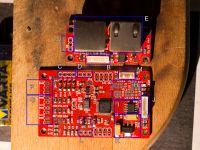
F - Second ADC channel, can be configured to measure voltage, current or connect a liquid flow sensor.
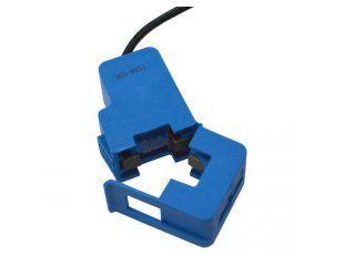
G - Channels 0, 1 and 3. Configurable in EEPROM as current measurement, light sensor or optical sensor that measures kWh using an external meter. In my case, channels 0 and 1 are set to work with current transformers, specifically:
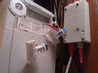
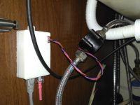
The last channel has a phototransistor connected, which, placed next to the energy meter diode, counts kWh from it, see the first photo.
C - I2C connector, allowing you to connect modules with various I2C sensors, the pins fit most Chinese boards, so if I came up with the idea of measuring humidity in the switchboard, it can be done.
D - Connector for 1-Wire devices.
M - SWD port. I liked the connectors from the Micro JST family (1.25mm) a lot. It is small and yet quite durable. The only drawback is the placement of the wires in the plugs. But you can always buy ready-made.
J - Same as B, only on the other side.

K - The power supply on the LM1117, the whole thing does not consume too much current, so there was no point in putting a typical pulse regulator there.
L - PIR sensor or flow sensor connector. Selectable via EEPROM, they still have similar voltage levels at which they operate. If you want, you can have a water meter instead of an energy meter. ;)
I - ST3485. The bark turned out to be somehow less problematic than the MAX3485.
H - Failure. Section responsible for radio communication using Si4455. The assumption was that since we set up one RS485 network per room, and there is no such network in the hall, all sensors "not related to the room" could be read and programmed by radio. And all in all, it would have been possible had it not been for the brilliant idea that the source of the clock for the Si4455 was the MCO pin of the controller (STM32F030). The controller has its own 30MHz crystal, it is on this side because it was uncomfortable for me to put it under the radio chip. And I have. The radio chip does not accept this type of clock signal. The only option for him is TXCO or normal quartz. Also in this version of the board, the radio does not work.
But it turned out that my multimaster protocol on RS485 works even better with a bus of around 20 meters than with a 5 meter bus. As usual, the CRC error rate was around 0.2%, so it has now dropped by half. I will not complain.
While the CT can be connected to the module directly, the voltage measurement module is not too high. The set includes a separate board containing the H11AA1 optocoupler and a set of resistors (2x470k from the diode side). This is not an ideal method of measurement - but in the future I will change it to some isolated differential amplifier and besides, I just need information about where and what was the hill and where the zero crossing occurred. With such assumptions, optical isolation "works". CTs are loaded with 100 Ohm resistors and have a bias of half the supply voltage, so the maximum voltage deviation for them is 1.65V + - 1V.
The ADC of the controller uses a 14Mhz clock, as a result the sampling rate is 333kHz, the ADC channels are generally set to 7, so it comes out at 47kHz per channel. The results are transported to memory via DMA. The actual measurements take place in the main loop of the program, not synchronized with the ADC operation. Every 50 full voltage waveforms, i.e. every 1s, the program performs calculations and stores the results in memory. From there, the system can transport them along the bus to their destination.
The housing, traditionally designed specifically for a given device and printed from ABS + on a 3D printer, has a place for a magnet, thanks to which it sticks to the switchgear non-invasively.
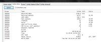
And the results:
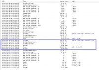
Ok for me. The first kWh meter is based on the measurements made by the meter. The second (with FF tip) is the reading from the blinking diode of the Tauron meter. Difference


Comments
And wouldn't it be better to buy the first Modbus meter from a Chinese and connect directly? Galvanic isolation, reading parameters, instruction. [Read more]
No. I can't plug something with the modbus protocol into this network that already exists. So I would have to make a converter there that will read data from such a meter and talk to the existing network.... [Read more]
Congratulations on making the project and I have this question regarding the CT transformer. What is the minimum current that can be indicated? What type (ratio) should I order if I would like to use... [Read more]
Excellent question, because I haven't checked it at the moment. But - it is not very stable below about 3VA or 13mA. Also does not really want to show 0, in the absence of load it spins somewhere [Read more]
Version number two https://obrazki.elektroda.pl/1401898300_1503483430_thumb.jpg Dimensions and overall design identical to the first version. Differences in details. Si4455 now has a crystal of... [Read more]