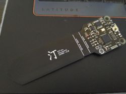
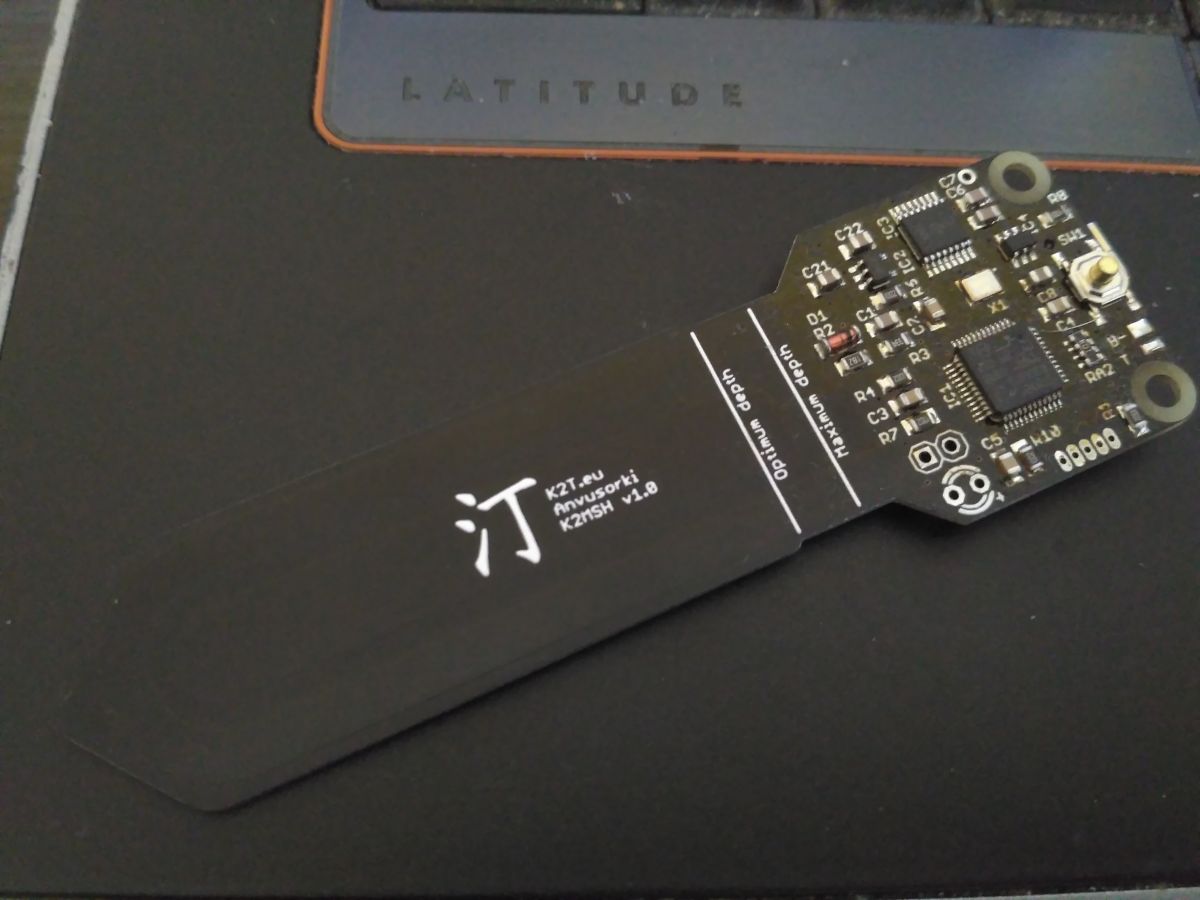
Since my girlfriend is a flower freak, she marked something to stick in the ground, forget about the fact that it is in the ground for a few months and in the meantime find out about how much water is in the ground (aka "when it's best to water" ), preferably via WiFi. With WiFi, nothing came out, because in total everything that uses WiFi has electricity consumption from space, and we want to have about half a year of work on a 300-400mAh battery. An option was still BLE (nRF52), but it also dropped out due to little convenience.
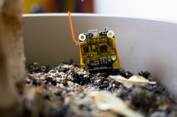
It ended up with the STM32F030 paired with the LT8920. The STM does not need to be introduced, and the LT8920 is a 2.4GHz radio transceiver, the main advantage of which is the small number of additional elements needed, all two capacitors and a 12MHz crystal are needed. In addition, the power consumption in sleep at the level of 6uA and the cost of 25 cents apiece. But there is no rose without thorns, the range is ok in practice, but it could be better: about 1-2 concrete walls, and terrible documentation.
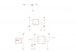
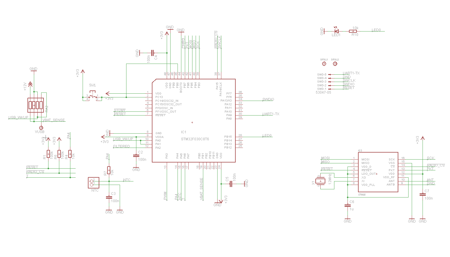
The humidity measurement is performed by the capacitive method:
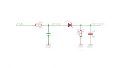
2.4MHz PWM signal with 30% duty cycle is fed to the input of the measuring system. After passing through a filter consisting of PCB tracks, any ambient water and R2 is flattened. We are interested at the moment what is more or less the maximum level after filtering, and this can be measured by a maxima detector composed of D1 (it is actually 4148 diode, there was no corresponding symbol in the eagle at hand), C1 and R3. After that, even a not too fast ADC and the determination of voltage levels in dry and wet environments for calibration is enough.
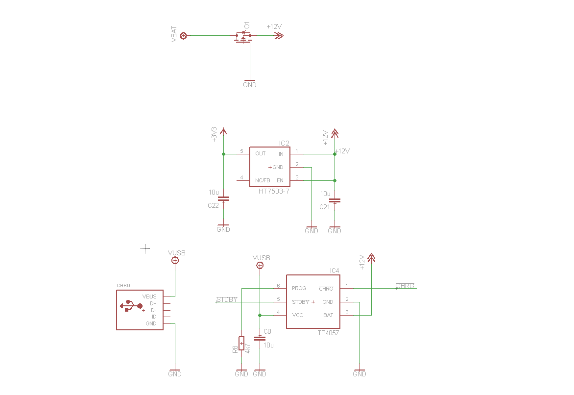
Charging via mini USB socket using TP4057, stabilization to 3V is provided by HT7530-7, both in SOT23-5 housings. The peak current consumption during measurement / transmission is about 60mA, 22mA in reception, and in sleep mode it does not exceed 30uA. Measurement / shipping takes place once every 5 minutes, it takes about 55ms. This theoretically should allow you to work with a 400mAh lipo battery for about 8 months, taking into account the 3% self-discharge and without considering the manual listening mode.
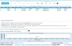
The system has one button, the operation of which differs depending on the holding time:
* single press - immediate measurement and sending the current data in the packet (LED blinking)
* hold for 3s - the system goes into the listening mode, it allows you to remotely switch to the bootloader and upload new firmware via the radio or read data live via the control unit, possibly also changing the parameters (LED flashing every 1s)
* hold for 10s - reset + bootloader input for 30s (LED blinking 3xs)
Currently, there is no other option to turn off data traffic than disconnecting the battery. But I think that changing the STM32F030 to F07x would give the option to configure via USB, useful in case of some very wrong settings. This, however, maybe in the next version, the current one works quite well for our needs.
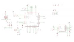
When measuring soil moisture, the system also measures battery voltage, optionally temperature (NTC), and USB voltage during charging.
A clock is used to collect data from sensors:
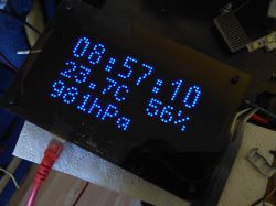
Built on STM32F107 (and 18 matrix displays 8x8 20 / 1.9mm), it has an Ethernet port, several sensors specifying the parameters of the environment in which it is located and a transciver on the LTC8920 which allows it to exchange data with sensors.

But this one will be described more precisely as my darling will do something meaningful with his WebUI


Comments
I understand that the fill and frequency of this signal is constant? What was the dictated choice of these parameters? [Read more]
Yes, she was. I experimented with the widest measuring range, in this case 2100 by 12bit ADC. [Read more]
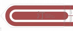
How do you protect the tile against moisture? [Read more]
I did not protect, the solder mask is water resistant, and the FR4 does not absorb it. One thing I did not mention - the sensors will get housings at a free moment so that an accidental clearing does not... [Read more]
A very nice design. Congratulations! I am interested in what is the matter with the antenna. Is it just a 1/4 wavelength piece of wire? You don't need any impedance adjuster or something like that?... [Read more]
And what's the range in open space? Didn't you prefer to use the 'L' series Prock. They are more energy efficient. [Read more]
Oh, thank you. Exactly. As I wrote, the documentation for the circuit is impaired and contains absolutely no hints as to what this circuit likes best for its antenna. And the sample layout in... [Read more]
The + 12V symbols on the diagram are probably an error? Have you been using these sensors for a long time? I am asking because I have been testing my version for several months and I noticed that the... [Read more]
Yes, I copied this fragment from another schematic where it was actually 12V and it just stayed that way. About a month and I noticed something like this, but it does not happen by itself, but for... [Read more]
Very nice design. Some time ago I made a similar project but powered by CR2032. It has been working on one battery for 4 months without a noticeable drop in voltage, so it should last a little longer.... [Read more]
Oh, thank you. I was wondering about 2032, but with the peak consumption of about 60mA, I found that I would not test how they would behave and I would take a safe option. ;) Hmm, I think that... [Read more]
The D1 diode disturbs the measurements a bit. This method of measurement was used in analog meters. Capacitance can be measured by measuring the pulse time, not the voltage. The diode is not needed and... [Read more]