 At the beginning, I would like to thank everyone who did not believe in me - my strength in you!
Table of Contents: [line: 2f4bfa70a4]
1. Introduction
2. Assumptions
3. Mechanics of movement
4. Why not CoreXY?
5. The final shape of the "cross"
6. Toolchange - a system of variable tools
7. Parking of warheads
8. Z axis
9. The table
10. Table clamping system
11. Main and subframe and its reinforcements, chamber
12. Electronics
13. Compressed air cooling system for printout
XX. What is he currently working on?
1. Introduction [line: 2f4bfa70a4]
My fun with 3D printing began with the purchase of the Ender 5 Plus printer, which itself is very correct and I recommend it for the beginning, but with time, when I learned about its advantages and disadvantages, I started to redo it, it started with electronics, then linear guides and in the end, I am satisfied with the results, but the construction itself has become a limitation.
In the meantime, as part of one of the subjects at university, I got to know the 3D design program - SOLIDWORKS and I decided that I want to learn how to use it, but for this I need motivation - so I will design a 3D printer as I would like to have.
The project started around mid-2020.
2. Assumptions [line: 2f4bfa70a4]
[letter = 1: 2f4bfa70a4]
[*: 2f4bfa70a4] Working area 400x400x400
[*: 2f4bfa70a4] Two extruders
[*: 2f4bfa70a4] System of interchangeable tools (development issue)
[*: 2f4bfa70a4] Cartesian mechanics - not CoreXY (I'll explain why below)
[*: 2f4bfa70a4] Zero rolls - only MGN12 linear guides
[*: 2f4bfa70a4] 230V table
[*: 2f4bfa70a4] Chamber
[*: 2f4bfa70a4] Controlled by Raspberry Pi 4
[*: 2f4bfa70a4] Printing speed> 300mm / s
[*: 2f4bfa70a4] Possibly light head
[/ letter: about: 2f4bfa70a4]
3. Mechanics of movement [line: 2f4bfa70a4]
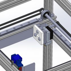
Initially, the mechanics were to be the same as in UltiMaker - linear shafts with a diameter of 8 mm forming a cross and a Chimera hotend in the center, but the first static analyzes in SOLIDWORKS showed that the 60 cm long linear shafts are too flexible and under a test load of 300 g in the middle they will bend by over 0.2mm and this is one layer - unacceptable. The solution was simple - use MGN12 linear guides instead of shafts.
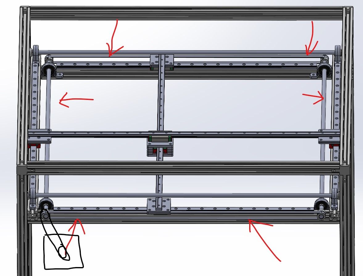
This is how the first version was created:

(Here the arrows show how the motion of one axis is "transmitted". The other is identical, rotated by 90 °).
4. Why not CoreXY? [line: 2f4bfa70a4]
The whole time I had a dilemma whether I was doing right with Cartesian mechanics instead of CoreXY. I was effectively deterred from CoreXY by how precisely a system must be designed in order for it to work precisely. In addition, CoreXY operates on straps, which in my case would be many meters. Such strips are subject to temperature which makes the strips susceptible to stretching under the influence of acceleration. Besides, the stripes require perfectly parallel guidance - without it the circle becomes an oval which is difficult to eliminate and detect.
I found the Cartesian system to be more predictable and simpler to design.
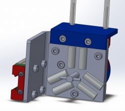
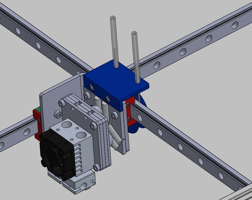
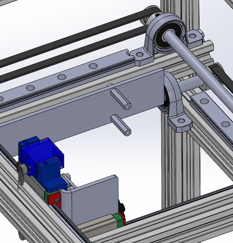
5. The final shape of the "cross" [line: 2f4bfa70a4]
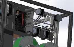
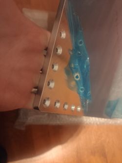
This stage caused me a lot of problems, because since the cross is not in the middle, there is no place for the printhead
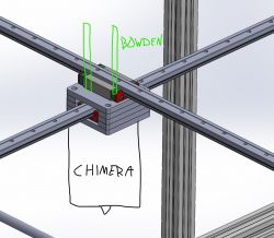
This photo best shows what the problem is - If you screw the hotend, it's not a problem, you need to route the filament supply tubes somehow.
I solved this by rotating the guides by 90 °, which allowed me to use an element that connects it in the form of an angle bar and moving the guide carriages apart, thanks to which I have an empty space above the extruder, which allowed for free routing of the bowden tubes supplying the filament.
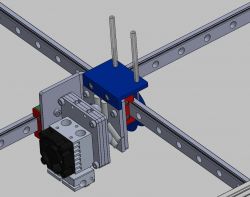
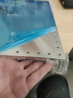
This photo shows what the next point will be about
but earlier
I would like to add that my friends told me that at speeds> 300mm / s, which I plan to achieve, the guides themselves may not be stiff enough, so the "cross" has been reinforced with Tslot 2020 profiles.
This solved another problem that I am the cause of
When ordering linear guides, instead of ordering 7x 500mm + 2x 600mm, I ordered 9x 500mm. The profile allowed me to screw the guides in the middle and the trolleys do not reach its end anyway.
6. Toolchange - a system of variable tools [line: 2f4bfa70a4]
It is one of the elements of this printer that appeared during the rebuilding of the head. I found that if there is a possibility then why not try it
There are few printers that can do this.
It is difficult to find information on how to do it, what are the advantages and disadvantages of a given solution, etc.
In fact, one solution dominates the market - e3d tool changer
When it comes to positioning, the only sensible solution is the so-called Kinematic Coupling (I have no idea what to call it in Polish).
This is based on six rollers (DIN 7 cylindrical pins) and three balls.
As a result, when one part is pressed against the other, they are always perfectly in the same position in relation to each other.
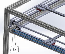
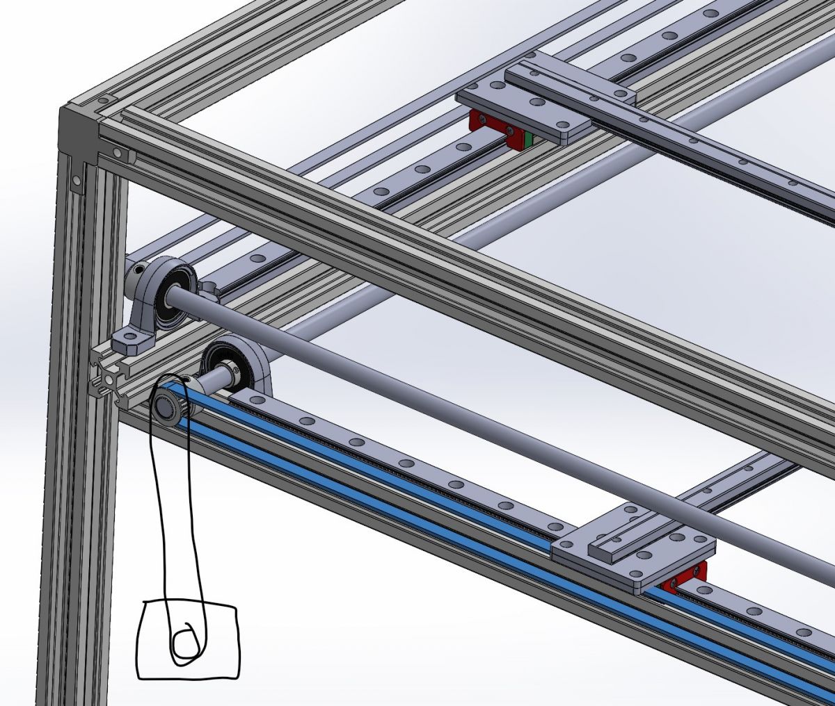
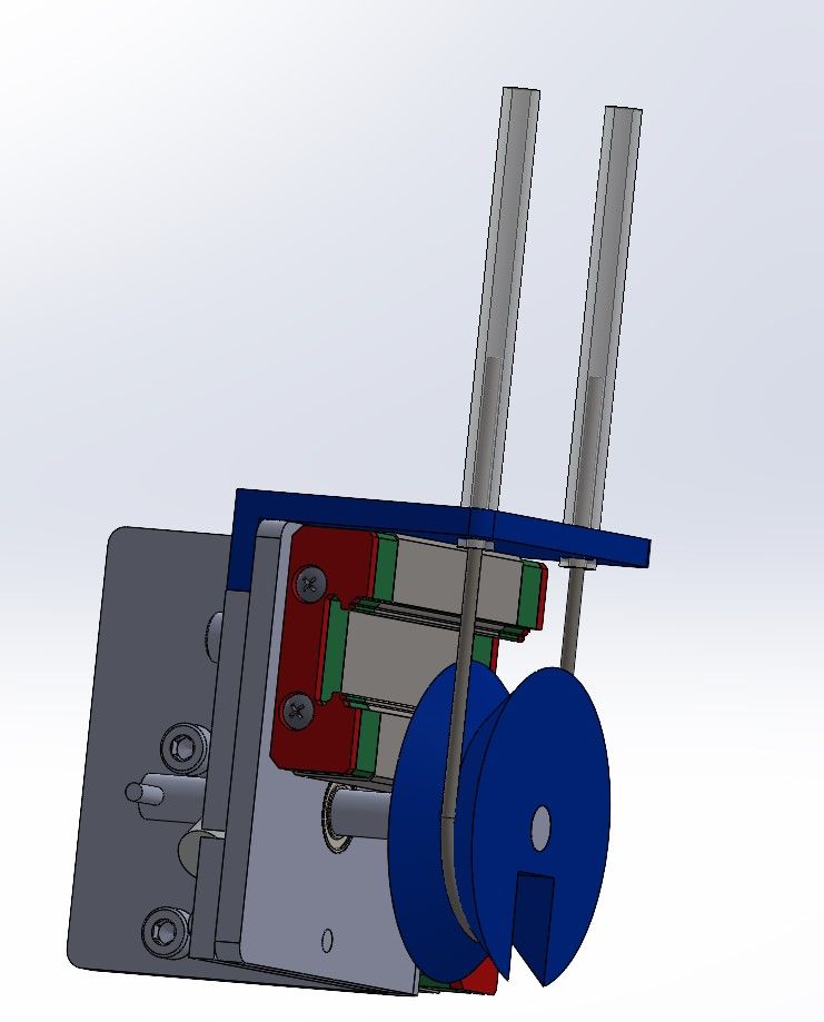
Another issue was locking the tool in the holder (locking and tightening). Initially, I planned a pulley and line system as in the video below:

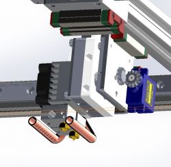
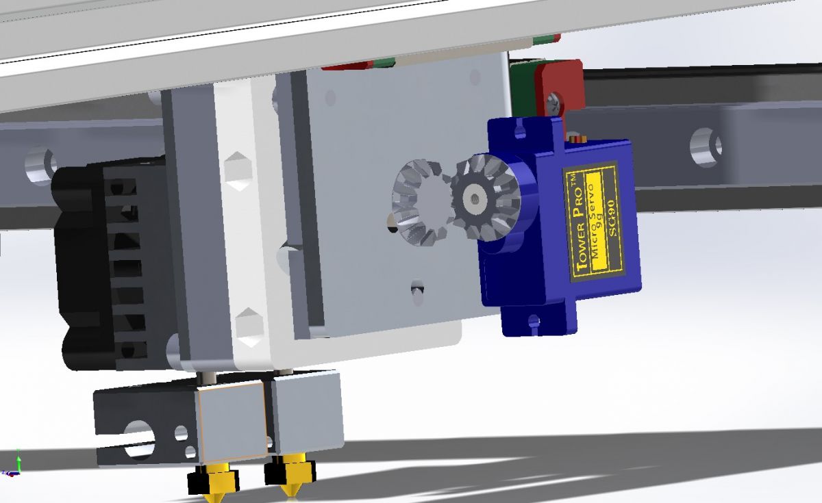
In the end it turned out to be a bit overcomplicated and I will eventually use a modeling servo. It can be controlled directly from the motherboard, is small and light, knows its position and has high torque.
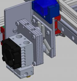
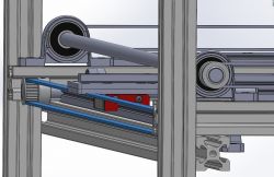
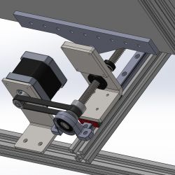
Unfortunately, the 2020 profile added to the guide prevented me from mounting the servo as in the photo above, so
I had to add a small angular gear - initially I planned to print it, but in such small details 3D printing is not very precise, but it turned out that the LEGO 6589 rack fits perfectly.
The servo mounting will design later, after starting the printer in the basic version.

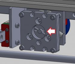
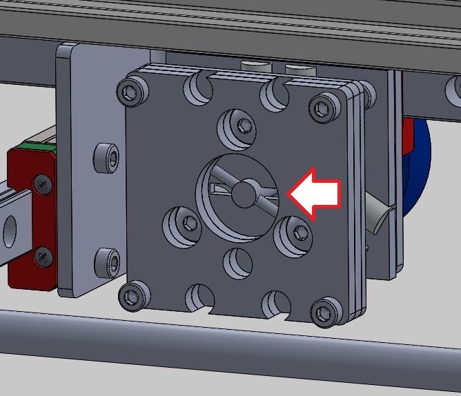
A big unknown for me is the system of tightening the head to the handle.
A friend from the Russian 3D printing community helped me a lot.
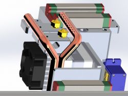
The photo below shows that the disc has two double helix surfaces. At the moment of rotation, the rod simultaneously tightens and locks the tool.
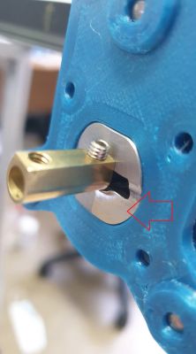
Can the servo do it? I do not know
If you have any idea how to solve it, I will be grateful! What are you planning for the tools?
[letter: 2f4bfa70a4]
[*: 2f4bfa70a4] Chimera hotend
[*: 2f4bfa70a4] 2.5W laser
[*: 2f4bfa70a4] Pisak
[*: 2f4bfa70a4] Spindle (something small, mainly for PCB milling)
[*: 2f4bfa70a4] It is possible that I will add a hotend with a large nozzle, e.g. 0.8mm to fillings, internal wall contours, etc.
[/ letter: u: 2f4bfa70a4]
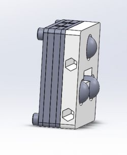
7. Parking of warheads [line: 2f4bfa70a4]
This is the part that I have temporarily stopped developing, so far I have an idea for it, but the success of the previous points determines what the final shape will be.
On the back of each head, he will attach a printed element having two spacer-shaped holes that are used to attach the PCBs to the housings. Two such rods will be placed in the parking lot and the head will rest on them.

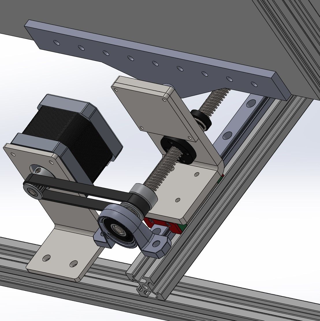
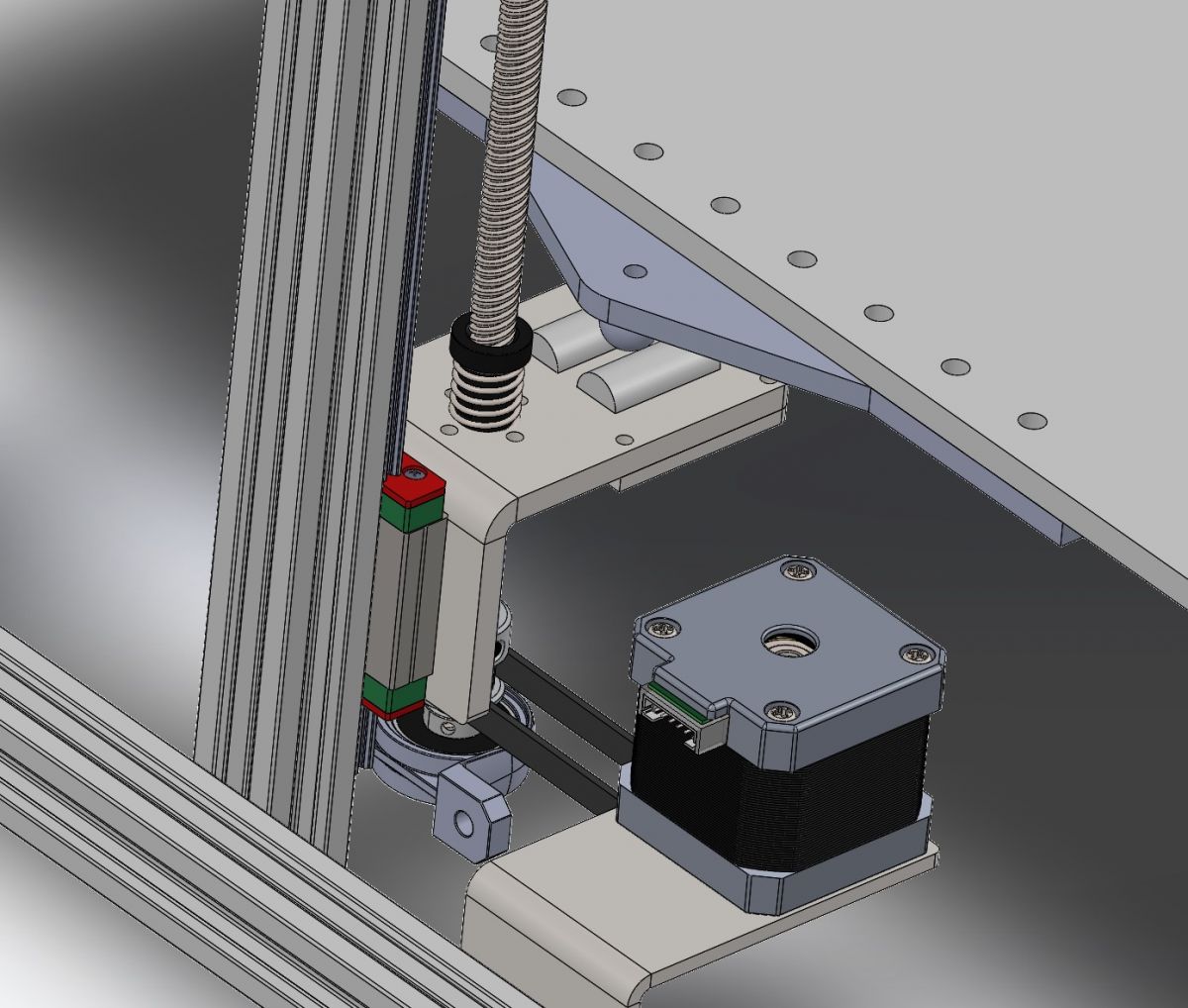
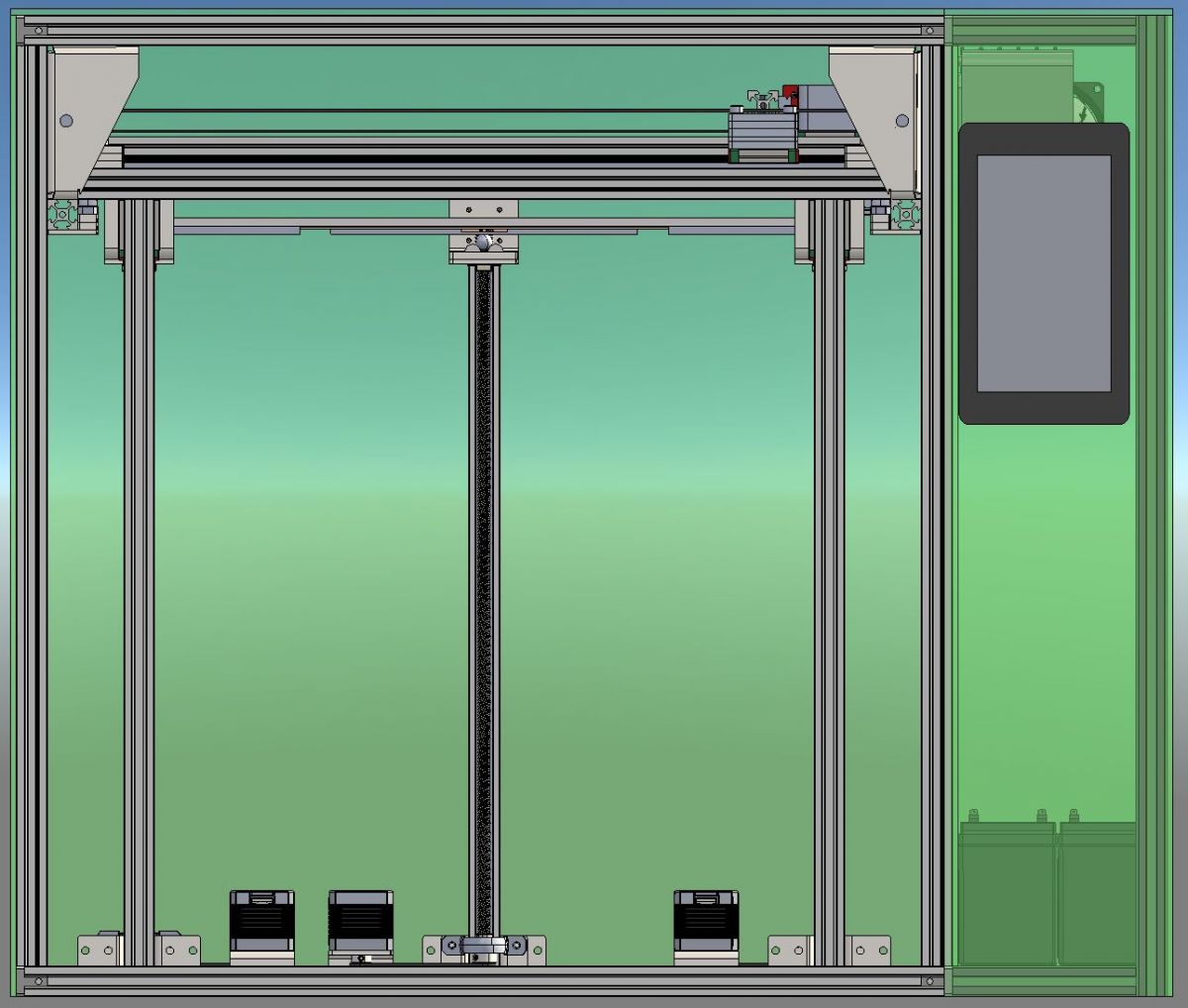
8. Z axis [line: 2f4bfa70a4]
In my printer, the Z axis consists of three independent "systems" - Z0, Z1, Z2.
Each of them consists of a Tr8x8 trapezoidal screw with a length of 500mm, a Nema17 motor, a backlash-free nut and a 500mm MGN12 linear guide.
The motor and bolt connection is realized with a GT2 belt (identical to the X and Y axes), eliminating the clutches that are often the source of the axial runout.
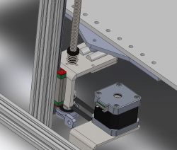
Originally I only gave one KP08 bearing, but it was rightly stated that the belt tension would cause the bolt to bend, so I added a second bearing above the sprocket.
This allows me to rigidly attach the table and only electronic leveling - based on BLTouch, i.e. a touch sensor based on a hall sensor and a magnet at the end of the rod. This gives perfect accuracy and repeatability.
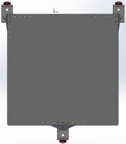
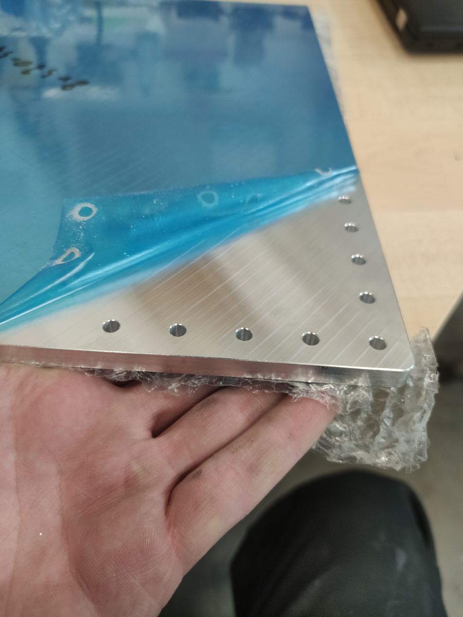
9. The table [line: 2f4bfa70a4]
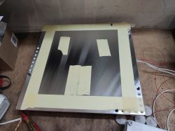
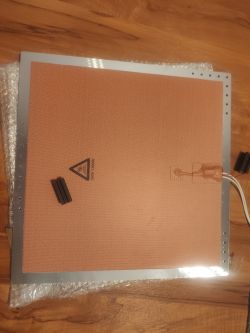
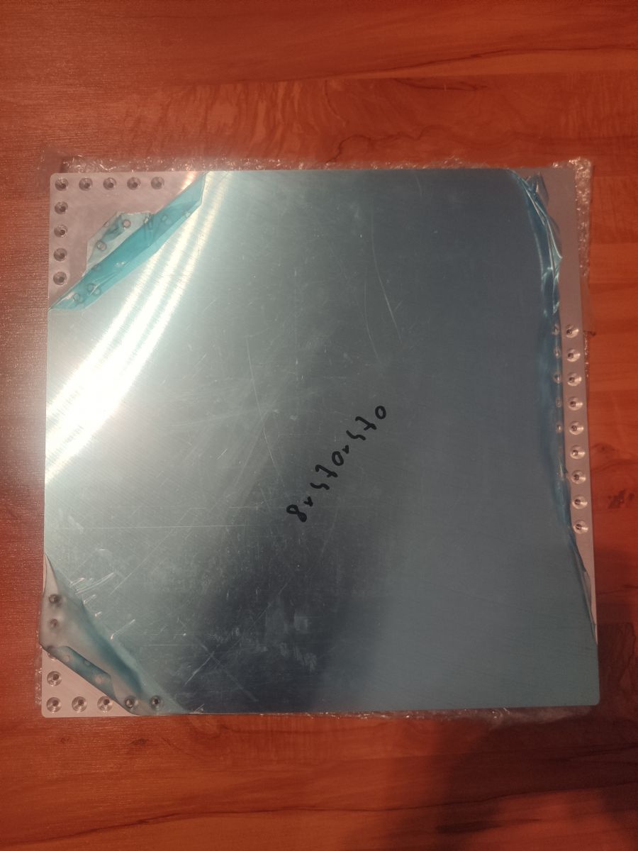
The table was cut for me from the G.AL C250 aluminum plate, i.e. the cast aluminum AW 5083, milled on both sides and thermally stress relieved. As a result, warping after heating should be as small as possible in relation to rolled aluminum.
The table is 440 x 440 mm and 8 mm thick.
The weight of the aluminum itself is about 4.5 kg, I estimate the top tempered glass and the weight of the entire table at 6 kg.
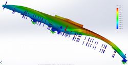
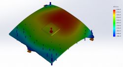
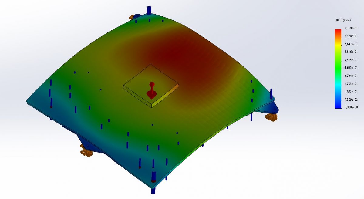
Below are the deformation analyzes
[letter: 2f4bfa70a4]
[*: 2f4bfa70a4] Load: gravity
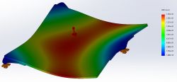
[*: 2f4bfa70a4] Load: gravity + 1kg with dimensions of 10x10cm (print simulation)
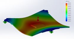
[*: 2f4bfa70a4] Load: gravity + 1kg with dimensions of 10x10cm + heating to 100 ° C
[/ letter: u: 2f4bfa70a4]
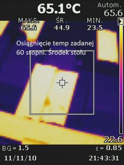
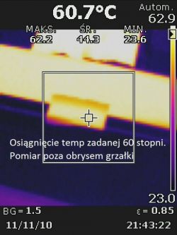
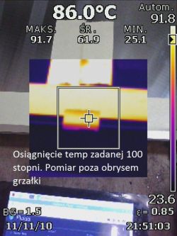
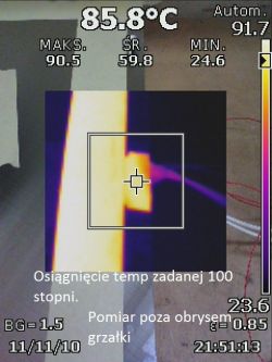
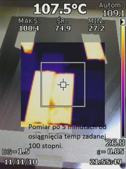
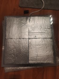
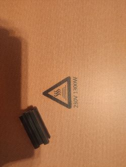
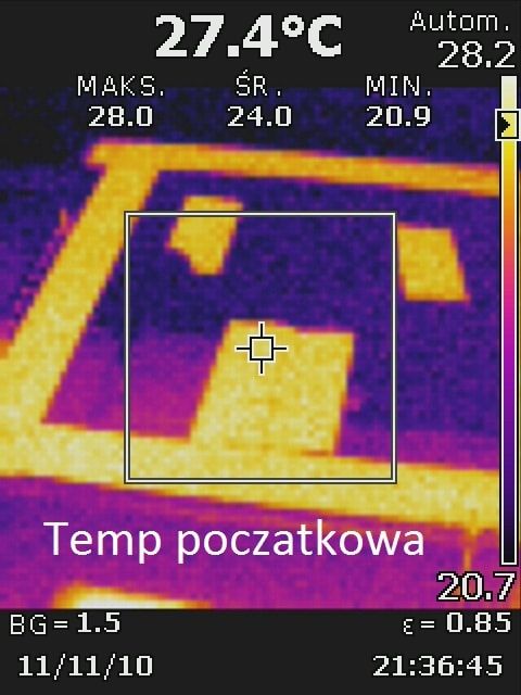
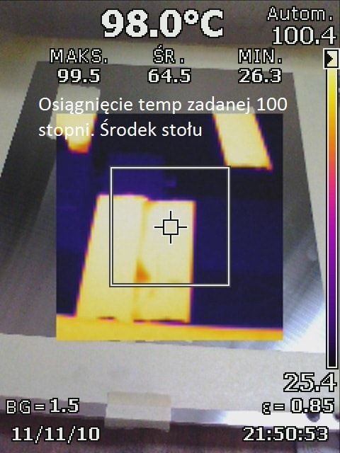
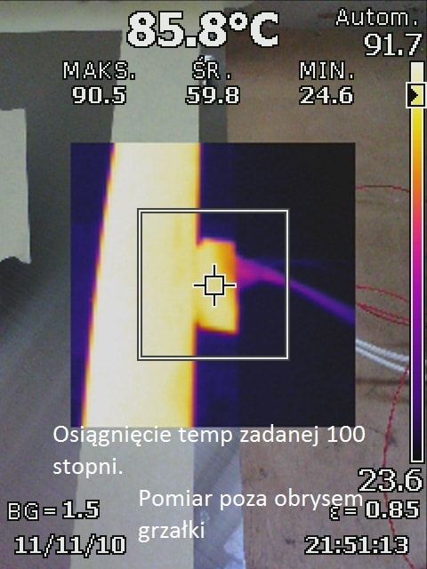
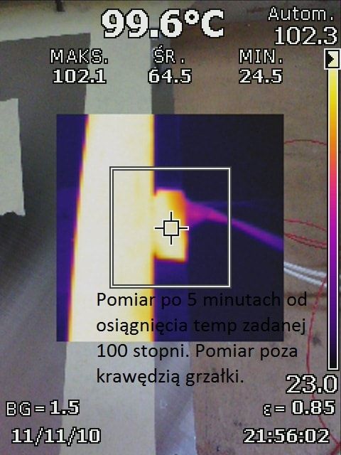
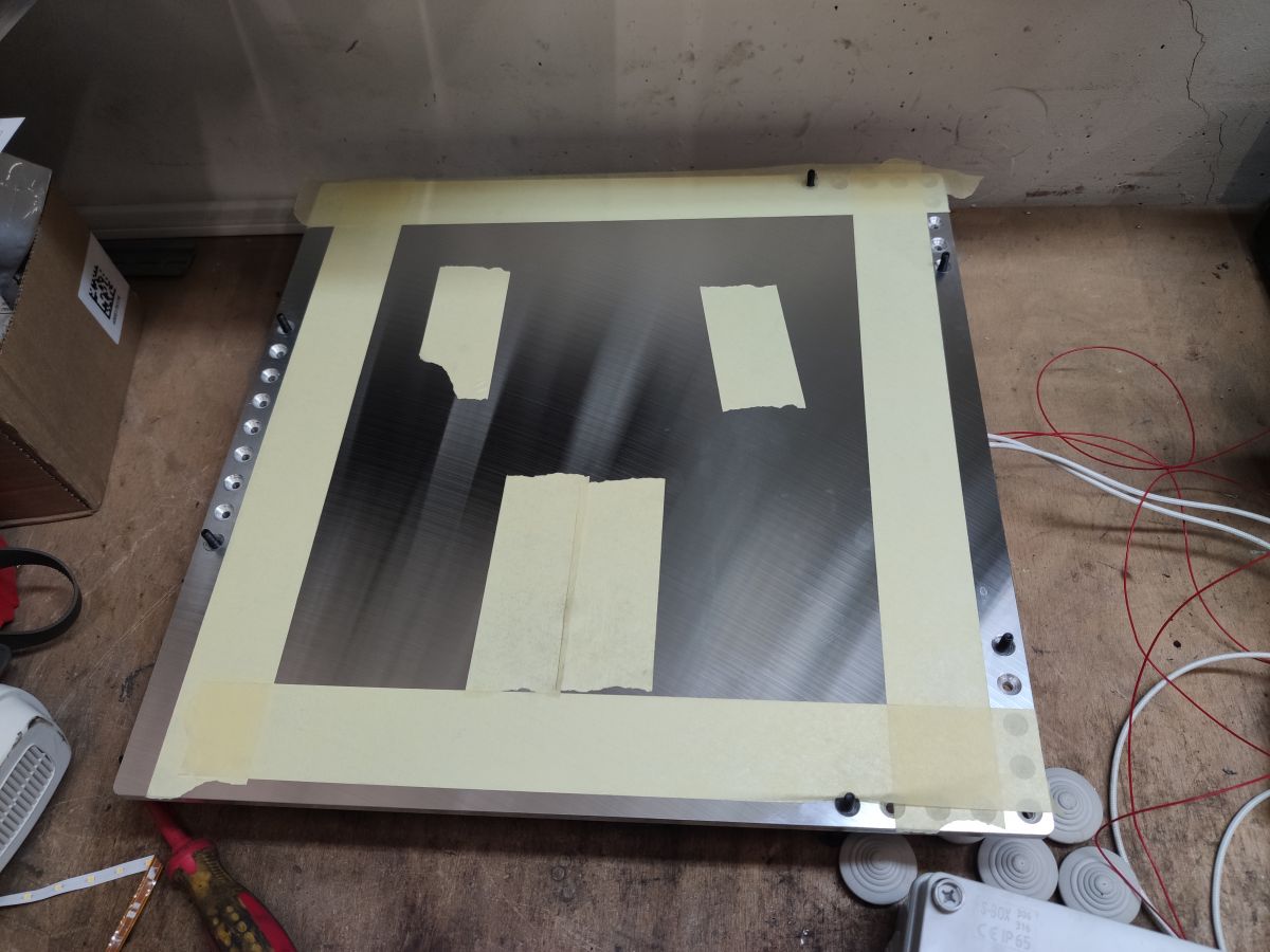
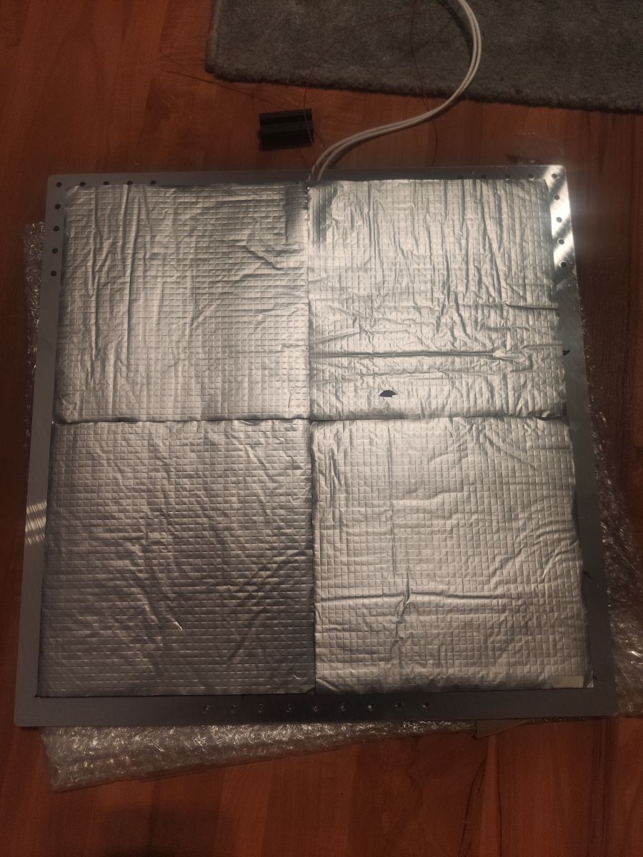
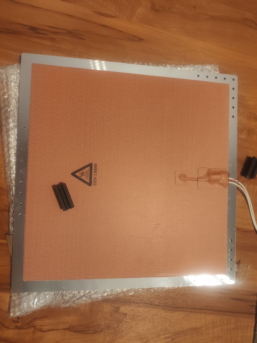
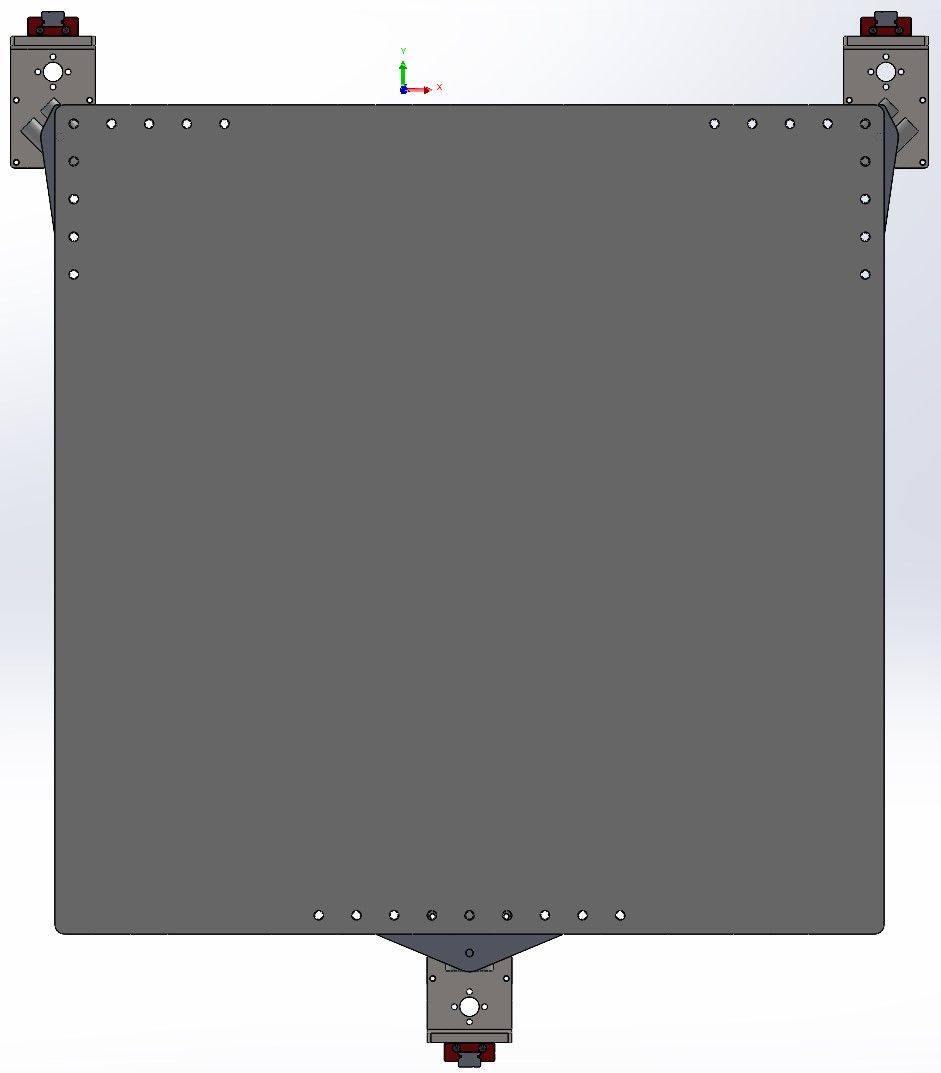
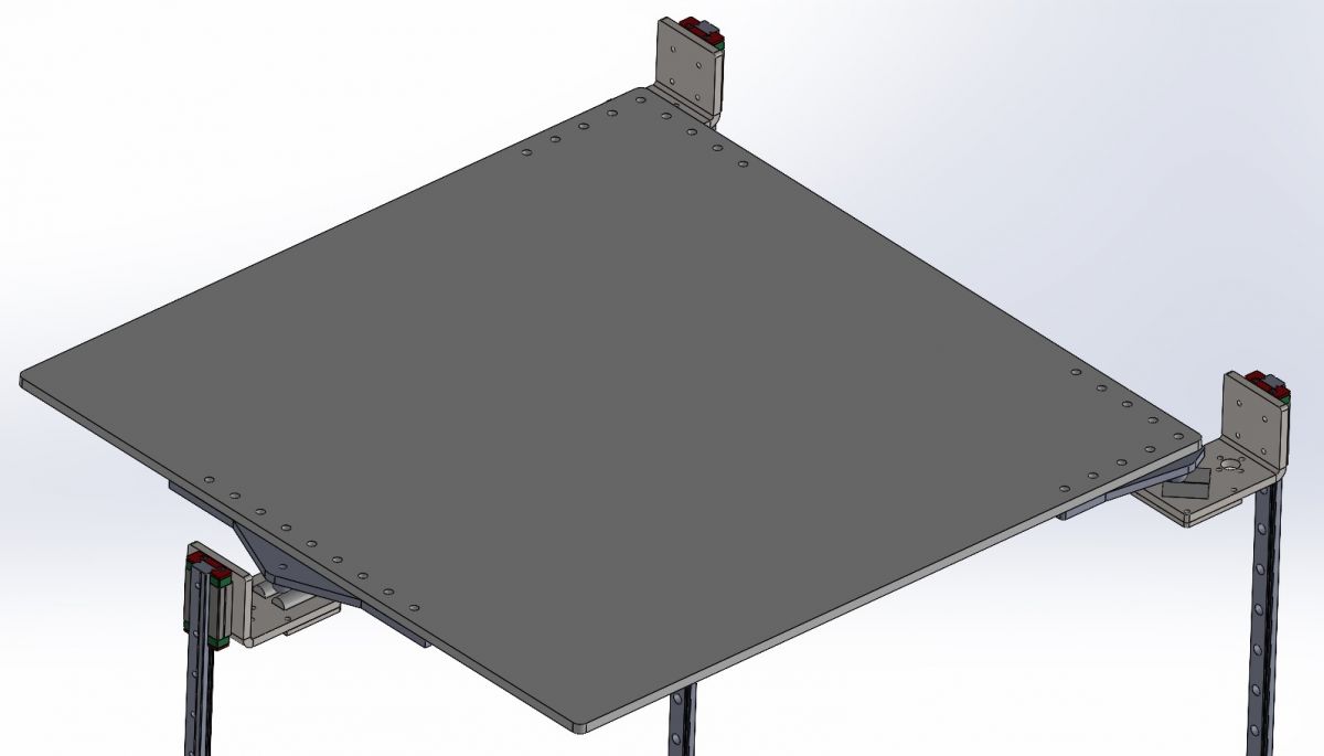
The table is of course heated. At the bottom there is a silicone heater with dimensions of 400x400mm and a power of 1300W, powered by 230V. The table is intentionally larger in order to be able to attach a frame made of 2020 profiles around the perimeter, if necessary.
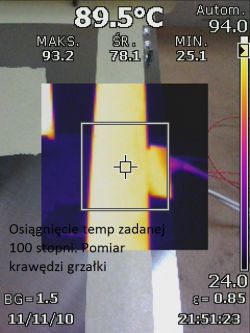
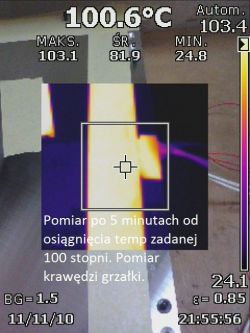
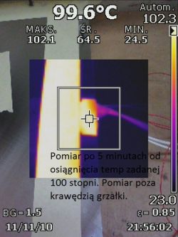
Below are tests performed with a Fluke Ti95 thermal imaging camera showing how the temperature spreads. I stuck a paper tape on the table, because the table effectively deflects radiation and is invisible to the thermal imaging camera.


 10. Table clamping system
 [line: 2f4bfa70a4]
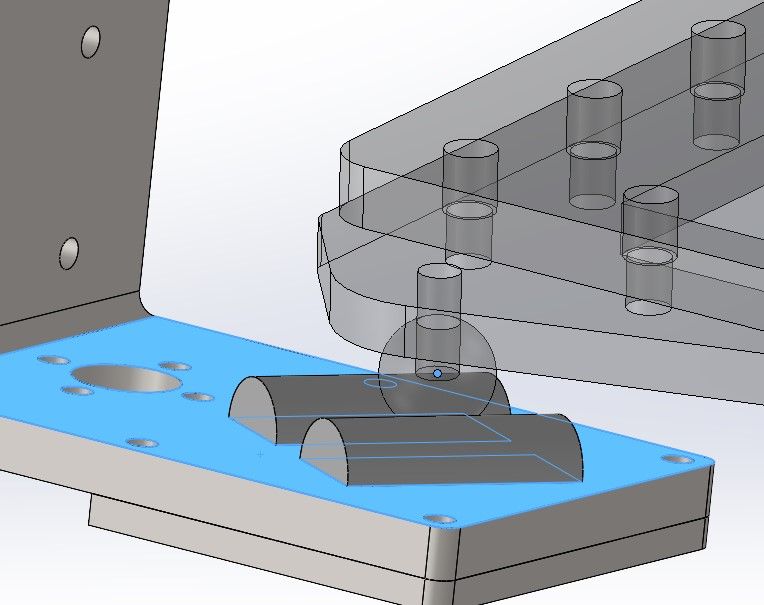
Due to the fact that the table will be leveled electronically, it must be able to rotate in relation to each of the Z axis, theoretically three ball joints are enough, but in practice heating the table from 20 ° C to 100 ° C will expand its dimensions in X and Y dimensions by 0.8mm. If a rigid clamp is used, the increase in dimensions will cause the table to warp.
For this reason, I used a system similar to the head mounting, i.e. also six rollers and three balls.

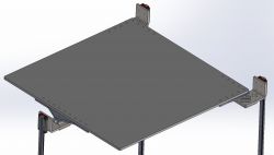
Thanks to this, I have the possibility of rotation and in the case of an increase in temperature, the balls will simply "spread" on the rollers.
Another advantage of this solution is the possibility of tilting the table and I am interested in the vision of "non planar" printing or, for example, reducing the number of supports, because the overhang angle can be reduced by tilting the table.
There is only one problem, I marked a dot in the center of the table and an identical dot in the center of the frame above the table.
When the table is tilted, the dots begin to "spread" in the X and Y axes up to about 2mm.
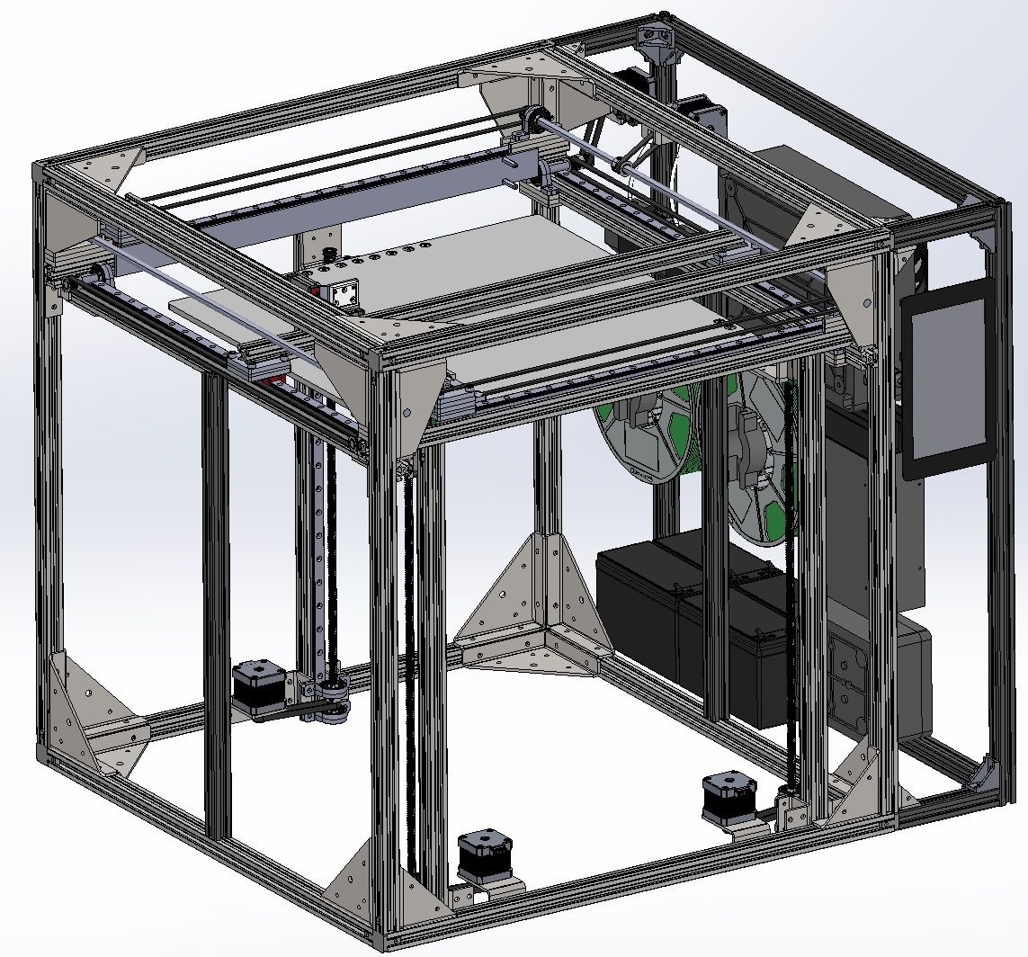
Do you have a problem, can it be solved somehow? 11. Main and subframe and its reinforcements, chamber [line: 2f4bfa70a4]
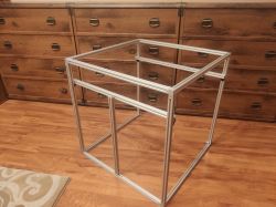
Initially, I planned to use Vslot 2020 profiles, but then it turned out that Tslot profiles are cheaper and more durable.
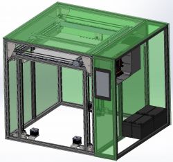
The external dimensions of the printer are 750x640x640mm.
The total weight according to SOLIDWORKS is 40.3 kg, but I do not have any bolts (I added maybe 50 bolts and yet the assembly has 997 components at the moment), so the final weight will be around 50 kg.
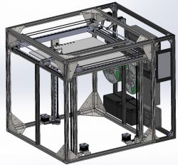
Due to the relatively thin aluminum profiles, each corner has been reinforced with a 3mm thick black steel corner, which will be laser cut and bent with a CNC bending machine, just like aluminum parts (movable parts are aluminum to reduce weight and the rest is steel)
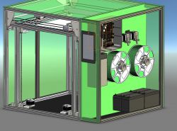
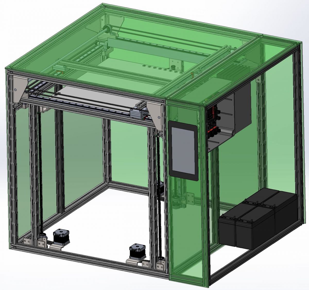
Chamber:
The chamber in the 3D printer is designed to provide a high temperature that surrounds the printout in order to minimize material shrinkage, which causes cracking and warping of the elements. The heat source in the chamber is a silicone heater attached to the table. The walls of the chamber are planned to be made of 5 mm thick foamed polycarbonate plates, which insulates heat well, and I will additionally cover it with an acoustic sponge from the inside, which will soundproof the whole thing and improve thermal insulation.


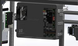
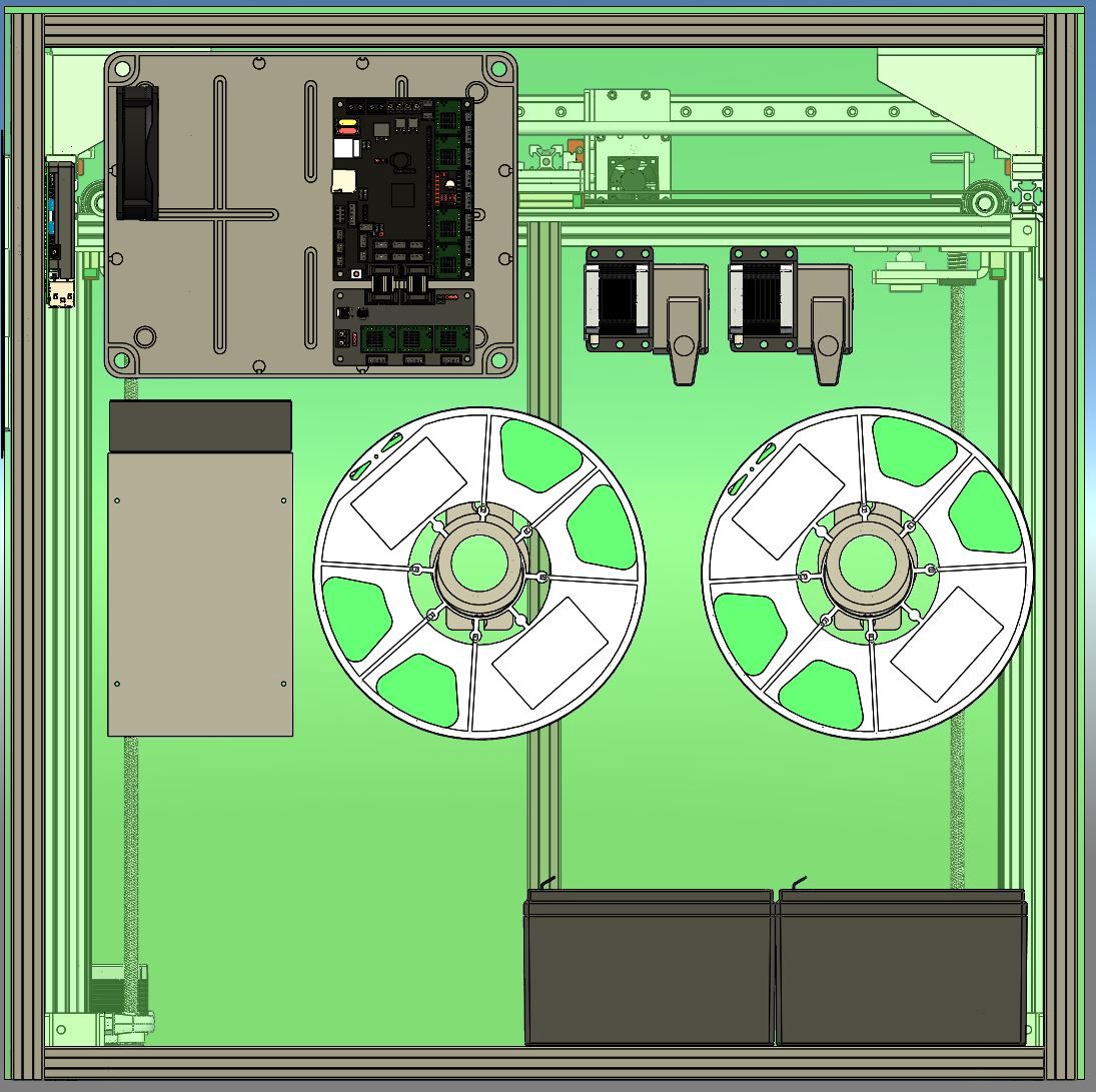
 12. Electronics
 [line: 2f4bfa70a4]
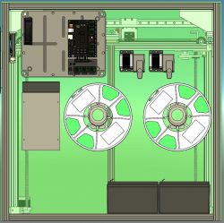
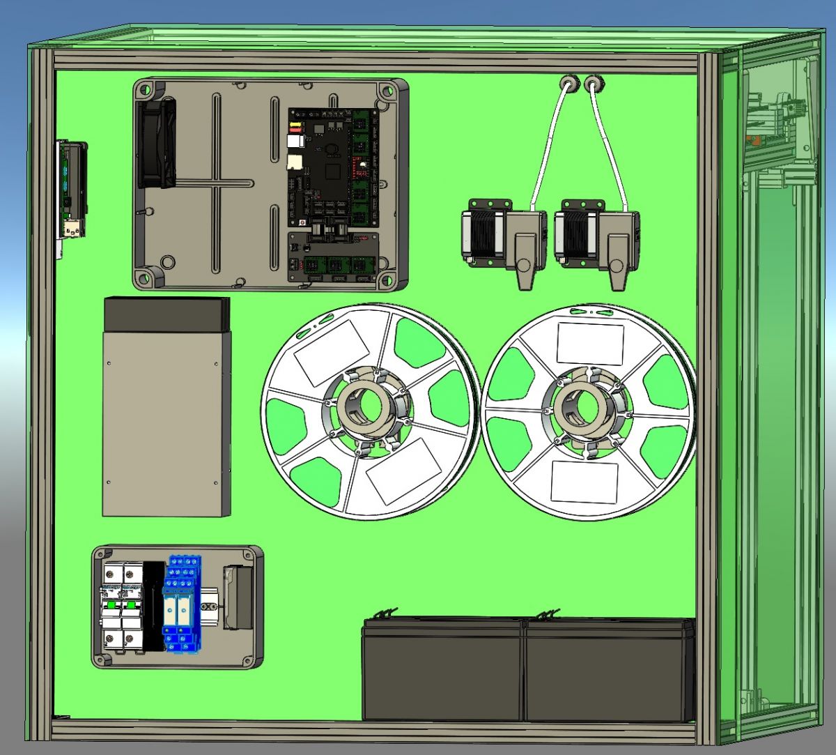
The electronics are divided into two boxes, one 230V and the other with "logic".
Inside the first one there are overcurrent protections for the entire table, the table and the 24V 300W buffer power supply, relays responsible for turning off the electronics from the Raspberry Pi level and the second responsible for the emergency button (mushroom), the 24V 0.5A standby power supply supporting the relay from the mushroom and the SSR relay controlling the table heater .
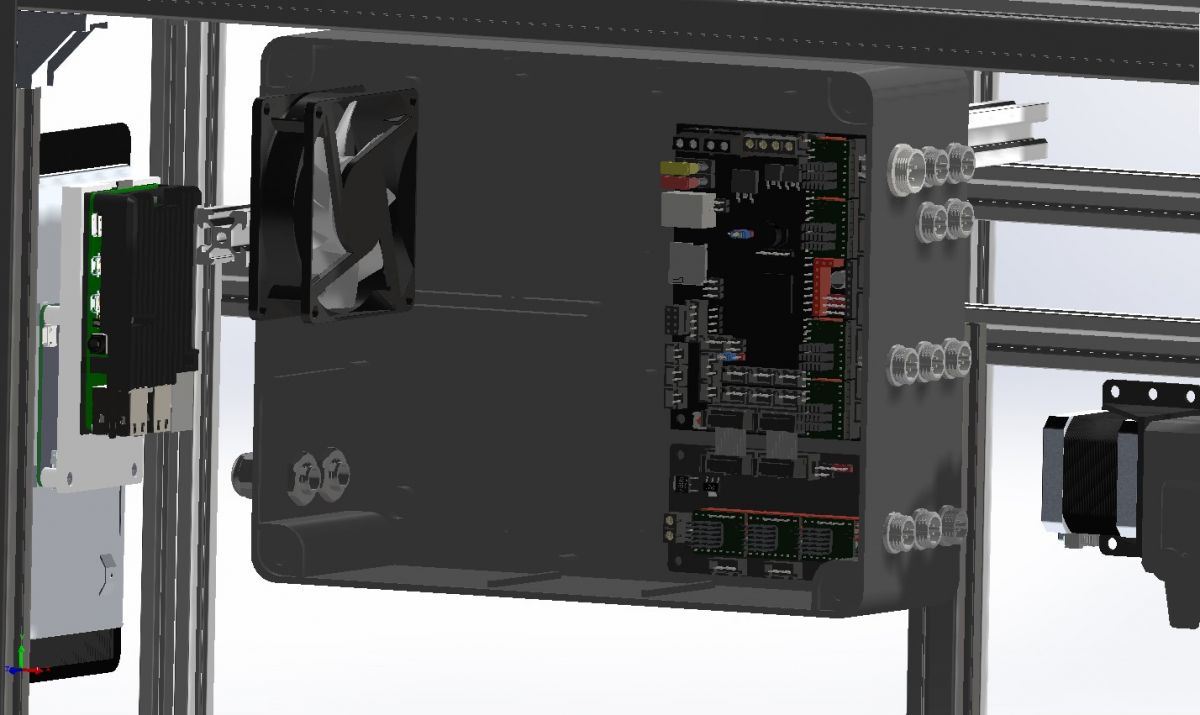
The second box only has a voltage of 24V and inside there is the SKR 1.4 TURBO main board with the BTT EXP-MOT module. Such a set allows you to control 8 stepper motors, but in this case 7 motors were used (3x Z, X, Y + 2 extruders) and each of them has a TMC2209 driver. The X and Y axis motors have a rotation angle of 0.9 ° which is 400 steps, the rest is the standard 1.8 °.
These controllers allow you to return to the zero position (homing) using the method called "sensorless homing", i.e. the lack of confirmation of the correct step by the controller, because the motor has reached the end position and pressed against the frame.
I do not know whether I will use this function or use optical limit switches.
In the meantime, I managed to buy the SKR GTR board, which is based on the STM32F407IGT6 chip and I will probably use it because it has several times more GPIO than that board and I lacked, among other things, one PWM port for servo control and the additional BTT M5 module allows for total control 11 engines.
The board will be controlled by Klipper Firmware, which is probably the only one suitable for such an extensive machine.
In order to function, apart from the "executive" board, the klipper needs a computing part, which will be performed by the Raspberry Pi 4 in the 4GB version of the framework.
A 5 "touch display is connected to the RPi via the DSI socket and the RPi itself is connected to the motherboard via UART.
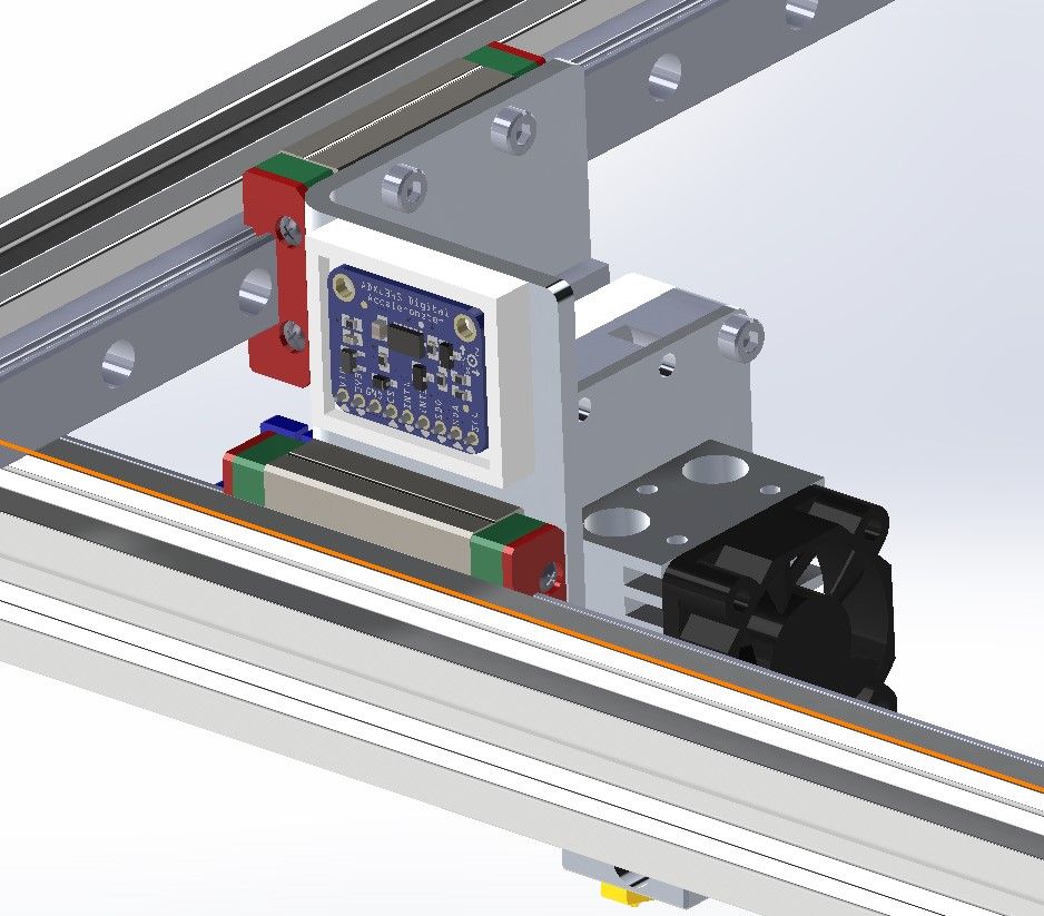
One of the interesting functions of the clipper is, for example, the ADXL345 accelerometer operation and the measurement of head vibration and resonance frequency as well as the selection of acceleration in such a way as not to lead to it.

As for the firmware inside the RPi, it is Mainsail + Fluidd graphic overlay.
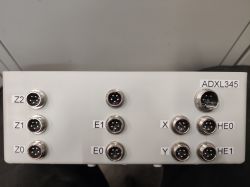
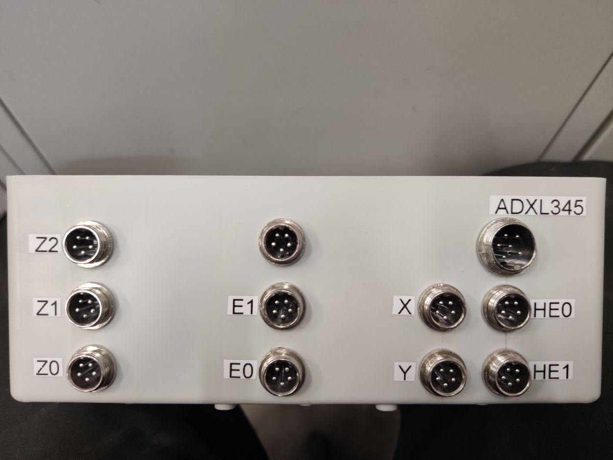
As the sockets connecting the second box with the world, I used the GX12 and GX16 sockets for the accelerometer. This allows for quick disconnection of cables and replacement of a given component.
 13. Compressed air cooling system for printout
 [line: 2f4bfa70a4]
Due to the small dimensions of the head (45x45mm), I was unable to fit the 5015 fan without excessively increasing the external dimensions.
I decided to move the "drive" outside the head and use an air pump called berd-air, which I will place next to the electronics.
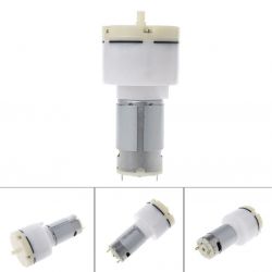
It is a diaphragm air pump powered by a 555 24V engine with a capacity of 15L / min. Thanks to this, I can only bring a silicone hose with a diameter of ~ 6mm to the head.
Due to the fact that compressed air will be useful not only for cooling the print, but also for removing smoke in the case of laser engraving of wood, I am considering making a servo-controlled distributor so as to be able to supply air to the heads that need it and control it to which at a given moment air is supplied.
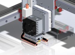
It is a copper tube with an outer diameter of 6.4 mm and a wall thickness of 0.8 mm, used in air conditioning systems.
Anyone have an idea how to bend it at such sharp angles without kinking?
Heat it with a burner?
Pour soapy water and freeze? (I did it, but with thicker ones) The ends will of course be sealed and the air outlet will be only 2mm diameter tubes.
XX. What is he currently working on? [line: 2f4bfa70a4]
Finally, after many months of designing and calculating, I moved to construction.
At the moment, I have assembled the frame and ordered laser cut parts.
The rest of the components are waiting in cardboard boxes for assembly, but I am stopped by the lack of cut elements.
Besides, I am finishing the electronics housings
As the work progresses, I will update this description, besides, I have for sure forgotten many things at the moment, so I encourage you to check if there is any EDIT ;)
If any of you know the solutions to problems with
bold I am asking for information.
Feel free to discuss, constructive criticism, advice and tips.


Comments
Very nice workmanship and idea :) Did you think about the costs, how would it go for the finished printer plus other heads? I understand the whole controlled by one program plus automatic change of heads... [Read more]
As soon as I am satisfied with the results, I plan to start selling the printer as well as the kit for its construction. The interest is considerable, because the presented printer, in my opinion, fills... [Read more]
In my opinion - it will not be cheap ;) The price of the materials themselves is quite easy to determine, a lot depends on where you buy. From my experience with MGN12 and this family of rails - recently... [Read more]
Honestly, every printer I know is based on stripes. In most designs, the X and Y axis is moved by one GT2 6mm belt, I will have two such belts in parallel (not counting the small 200mm drive loop). Fortunately,... [Read more]
In my opinion, you must take into account that the table surface does not pass through the pivot points of the table when tilting it. And this has to be calculated when printing. Note that such a point... [Read more]
That little friend saw. Printers with interchangeable heads - 3dgence Ball screw printers - dragon3d [Read more]
https://obrazki.elektroda.pl/6257240800_1614414141_thumb.jpg https://obrazki.elektroda.pl/9670105300_1614414145_thumb.jpg You'll admit there are two different "definitions" of interchangeable... [Read more]
Ball screws were used in SMT machines of this type https://www.youtube.com/watch?v=xNRAFwfCHv0. They are powered by small Panasonic AC motors (0.64 Nm). The traversing speed is really impressive. The entire... [Read more]
I am really surprised by the speed of movement of this machine! Honestly, I will consider these propellers to drive future designs. My motors are 0.26Nm. I was able to find the servos used in the machine... [Read more]
These motors are cold when running. [Read more]
I have Hbots, Atmata, and one Dragoon at work. If you want to see something, let me know. Hbot, Dragon and 3D gence are all Polish constructions. But dragon, despite the use of ball screws, is rather the... [Read more]
Many people suggested that I stick a PEI sheet directly to the aluminum plate, but I was not convinced by this idea. Due to the fact that I intend to use a 100% laser head (I have a 2.5W laser, mainly... [Read more]
As for strain gauges, these printers have been tortured almost continuously (even on weekends) for 3 years and there was no failure. There is boron glass in the habots, on which a piece of Kapton tape... [Read more]
Do you have any bearing on a metal pin? Unfortunately I can't find anything on sale. I once replaced the pin (ordinary, plastic), but only through my own fault, I changed the mounting and forgot... [Read more]
These pins can be bought for pennies on Ali ... and a little more expensive on Ale ....... Once upon a time I found on Ale ....... but now I can't see. But they do appear. [Read more]
Great design. My advice is only about electronics. I would avoid SKR products with such advanced mechanics. The support from the producer ends with the typical Chinese "Sorry My Friend". I am an unhappy... [Read more]
Literally yesterday a version of Marlin with usb support appeared ;) I invite you to priv, I will send you the contact details. Nevertheless, it is a very archaic project, most of its functions are... [Read more]
And I checked. The nut on the ball screw has the symbol: HIWIN S1600VE-1 082 The engines are: MICROCON SX23-1414 I am missing something in your printer. I assumed that (I don't know if it is right)... [Read more]
Item 11 describes how he plans to make a chamber. In most of the photos I have hidden covers, because even with the transparency on, they make it difficult to see the structure. The filament will be... [Read more]