Tasmota replacement for BL602, programming, pairing with Home Assistant, now with OTA working!
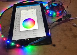
I will present here my Tasmota replacement designed for the BL602 platform by Bouffalo Lab, offering, among others. the ability to pair our device with Home Assistant via MQTT. I will show here how you can easily upload the batch to the BL602 using a simple USB to UART converter, and I will also describe the SDK compilation process for people who would like to program this platform on their own. In addition, I will present two interesting demos from SDK BL602.
Why program BL602?
The motivation is the same as with the platforms I discussed earlier. Own firmware allows you to free the IoT product from the manufacturer's servers, avoid possible loss of control over this product when these servers go down, avoid tracking and collecting data by the manufacturer, and additionally allows you to combine products from different manufacturers into one ecosystem. What I'm creating here is a "Tasmota" for other platforms.
Used module with BL602
Modules with BL602 (or related) systems can be purchased at relatively low prices, but the main principle of my operation is "release" of finished IoT products with closed programming of their manufacturers, so I used such a product for this topic.
It served as a testing ground for me RGB LED strip with IR remote control and WiFi - MWIR-RGB Magic Home Pro .
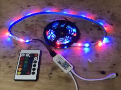
I described the details in the "Device interiors" section:
https://www.elektroda.pl/rtvforum/topic3881416.html
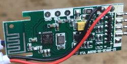
On board this driver is BL602 and 3 transistors controlled by PWM:
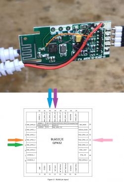
Connection sketch:
What firmware is this?
The firmware repository is here:
https://github.com/openshwprojects/OpenBK7231T_App
My firmware for BL602 is basically a port of my OpenBeken, actually OpenBeken has been reworked so that it is now a cross-platform application supporting the BK7231T, BK7231N, XR809 and BL602 chips.
The initiative was launched on these topics:
WB2S/BK7231 Tutorial - we create our own firmware - UDP/TCP/HTTP/MQTT
[BK7231T] My HTTP server, configurator, MQTT support with Home Assistant
For the user - downloading the compiled OpenBL602/OpenBeken batch for BL602
My Github repository has a script that automatically compiles online binaries for the BK7231N, BK7231T and XR809 platforms, unfortunately BL602 is not yet supported by it.
For this reason, the batch should be downloaded from the releases_bl602 folder:
https://github.com/openshwprojects/OpenBK7231T_App/tree/main/bl602_release
In the future, this may change and we will download the batch from the "Relases" tab on the right.
For the user - hardware connection
You need a USB to UART converter with 3.3V logic levels, a 10k resistor, maybe a 3.3V LDO regulator (as it is not on our board) and wires.
We connect:
- RX from the module to TX UART
- TX from the module to RX UART
- BOOT from the module to the 10k resistor to the power supply, but we leave it open (we connect it only for programming)
- weight to weight
- 3.3V power supply (if there is an LDO on the board, we can give 5V to its input from USB)
Details here:
https://www.elektroda.pl/rtvforum/topic3881416.html
For me it looks like this:
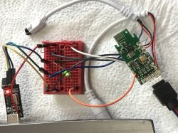
NOTE: If you connect the 5V power supply from USB to the LDO input (or step down converter) on the BL602 board and then connect the 12V power supply, you will damage at least the USB to UART adapter and maybe also the USB itself ... during programming disconnect the external power.
For the user - uploading the batch
In order to upload the batch, we need to:
1. Connect the BOOT signal to the power supply through a 10k resistor
2. Disconnect and reconnect power (reboot with BOOT signal up to power)
3. In BLDevCube.exe, select the following files:
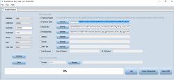
4. Make sure that the UART port is not in use (e.g. if we do not have it open in RealTerm - if so, we close it)
5. Click "Download" (which means "send the batch to BL602"):
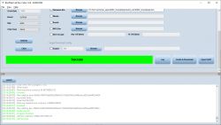
Ready!
Now, to run the batch, we disconnect the BOOT (leave it loose) and disconnect the power for a while, then restore it.
Device logs will still be available with baud = 2000000 (as in SDK demos).
For the user - OpenBL602 configuration
The configuration of my batch port on the BL602 is analogous to the configuration described in these topics:
- Qiachip Smart Switch - BK7231N/CB2S - interior, programming
- Garden double relay Tuya CCWFIO232PK - BK7231T - programming
It is also worth reading the topic:
Tutorial Home Assistant - configuration, WiFi, MQTT, Zigbee, Tasmota
After restarting the device, an open Access Point with a name like OpenBL602_1A1B2C3D4E5 should appear:
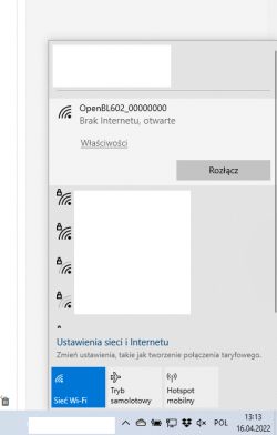
We connect to it and open the page with the address 192.168.4.1. We configure it just like Tasmota (we give the directions for our WiFi, we set the roles of pins, we give the directions for MQTT ...
For this particular RGB LED strip, the roles of the pins are as follows:
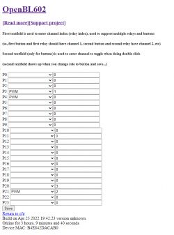
In the current version, my firmware does not support the IR remote that has this bar.
For the user - pairing with Home Assistant
There is a "Generate Home Assistant Config" option in the OpenBL602 panel, but it is not always enough. In the case of the RGB controller, this option "doesn't know" that you need to combine three PWMs into one color controller.
For this reason, I recommend taking only the device name from it, e.g. obl42DACAB0 and inserting it manually into this template:
Code: YAML
We save it in configuration.yaml. If we have several lights, we put the light prefix with a colon once.
After restarting Home Assistant, we can control the bar:

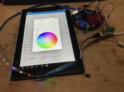
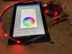
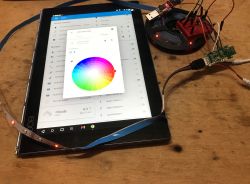
The current version has a drawback - after restarting Home Assistant does not read the current value of brightness and color. This will be replenished, but it does not affect the control of this bar.
For the programmer - MSys2 installation
You do not need to compile the firmware yourself, because I provide ready-made binary files. But if you want to modify my code yourself, you'll still need to learn how to compile. You will need MSys2 to compile the firmware. It must be downloaded and installed from here:
https://www.msys2.org/#installation
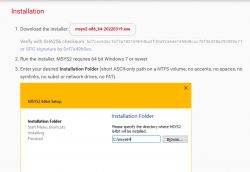
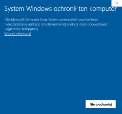
Windows may be blocking MSys - proceed anyway.
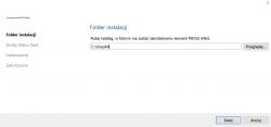
We select the installation directory:
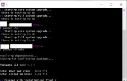
After installation, run msys2. It still needs to be updated.
We execute the command:
pacman -Syu
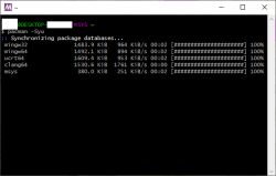
Then also pacman-Su
Then pacman -S make
For the developer - download the SDK and compile the project
Unfortunately, this is where things get complicated. The official SDK is here:
https://github.com/pine64/bl_iot_sdk
As of today (April 2022), however, the latest version of the SDK from Github does not compile correctly, you should use the older version, more precisely b3898a520d6e5a34a5f4de8241fcc1c1d3b071b9.
People other than me are also having problems with compiling the latest version:
https://github.com/pine64/bl_iot_sdk/issues/94
NOTE: If you are downloading the SDK with the intention of using it to build my project, please download my modified version from here:
https://github.com/openshwprojects/OpenBL602
This is because the main OpenBK (or OpenBL) application, called App, is shared between various SDKs of different platforms, and these SDKs themselves contain the basis of projects in which these main Apps are compiled.
Projects in the SDK are located in the customer_app folder:
Here is their list:
benchmark_security_aes
bl602_boot2
bl602_boot2_mini
bl602_demo_event
bl602_demo_joylink
bl602_demo_nano
bl602_demo_noconnectivity
bl602_demo_wifi
bl602_huawei_cloud
sdk_app_audio_udp
sdk_app_ble_sync
sdk_app_blog
sdk_app_cli
sdk_app_cronalarm
sdk_app_dac
sdk_app_easyflash
sdk_app_event
sdk_app_fdt
sdk_app_gpio
sdk_app_hbnram
sdk_app_heap
sdk_app_helloworld
sdk_app_http_client_socket
sdk_app_http_client_tcp
sdk_app_i2c
sdk_app_ir
sdk_app_mdns
sdk_app_pwm
sdk_app_romfs
sdk_app_spi_pdm
sdk_app_spi_wave
sdk_app_timer
sdk_app_uart_ctl
sdk_app_uart_echo
Compilation comes down to going to the folder of a given project and calling ./genromap
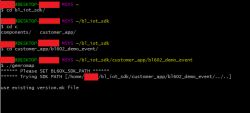
You still need to call:
- export BL60X_SDK_PATH=~/your_path_to_Sdk/
- export CONFIG_CHIP_NAME=BL602
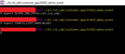
But in my experience, it is usually not needed and the script itself finds the path by assuming that the SDK is two directories higher than the project being built. In turn, CONFIG_CHIP_NAME is required if we want to execute the "clean" command of the project to remove intermediate .o files generated by the compiler, which are then linked by the linker.
The generated files are in the build_out folder, for example: customer_app\bl602_sharedApp\build_out
For developer - Demko sdk_app_gpio
Now that we can compile on our own, it's time to test the functionality demos provided by the developers of the SDK.
One of the most interesting demos is sdk_app_gpio.
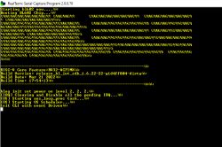
The sdk_app_gpio demo allows you to configure GPIO pins from the UART console. The command syntax is "gpio-func ".
For example, the command:
gpio-func 8 0 0 0
configures GPIO pin 8 as an output without pull up/down resistors.
The baud of a demo is 2,000,000.
This is what the demo looks like when launched:
After sending the pin control command:
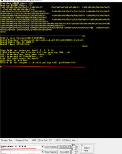
Then you can set this pin low or high with:
gpio-set
In the case of the input pins, we have an analogous UART gpio-get command:
gpio-get
For the curious - the implementation of gpio-func looks like this:
Code: C / C++
In turn, setting the pin:
Code: C / C++
Retrieving its status:
Code: C / C++
For the developer - Demko bl602_demo_wifi
Another interesting demo from the SDK is a program showing the operation of WiFi. Here we also control it through UART commands. Baud as before.
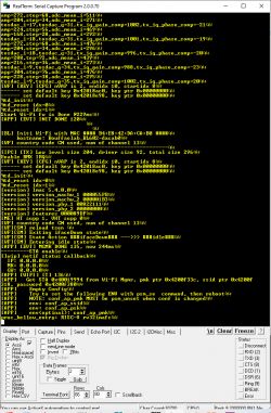
To begin with, it is worth getting to know the entire list of commands through the quite obvious help command:
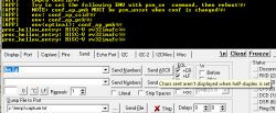
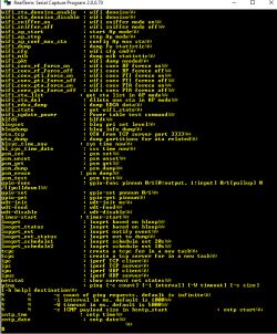
Let's try wifi_ap_start:
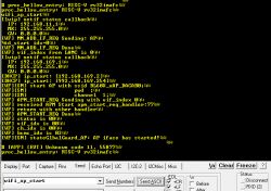
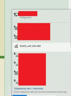
wifi_scan also works. We have the entire code of this demo so we can see what and how it is implemented.
Update 2026
As of 2026, this platform read/write is also supported by our flash tool:
https://github.com/openshwprojects/BK7231GUIFlashTool
The connection (soldering, wires), is the same, but you can use our tool instead of the legacy one.
Please check it out and use it instead of legacy tools, let us know how it works for you!
Summary
Another platform released! I started with release XR809 , then I took care of BK7231T and BK7231N . Now BL602 has been released. Next in line are the Realtek and W600 systems, but will it work with them too? We'll see.
In the queue for programming, I still have a bulb with BL602, but I don't think there will be any problems with it - on the board with the Wi-Fi module, pads are required, i.e. RX, TX and BOOT. I will put the description in the "device interiors" section.
As for the stability of the current version of the firmware for BL602, I tested it for two days, including deliberately turning off the router (checking if it catches the disconnect event and reconnecting) and I did not encounter any problems, but of course I will continue to test and fix any problems on an ongoing basis.
For details about the project, please visit its official repo:
https://github.com/openshwprojects/OpenBK7231T_App
PS: If you know any IoT or similar devices based on BL602 or a related system, let me know - I am constantly adding support for new functionalities to the firmware and collecting information on how it works. From what I know, the Sonoff 40, for example, probably uses the BL602.


Comments
Can you provide a link to the description of this Sonoff model? I can`t find it. [Read more]
https://itead.cc/product/sonoff-iplug-series-wi-fi-smart-plug-s40-s40-lite/ https://obrazki.elektroda.pl/9773326300_1650823264_thumb.jpg https://obrazki.elektroda.pl/8958773400_1650823318_thumb.jpg... [Read more]
Beautiful. I follow the posts of my friend @p.kaczmarek2 and I am very impressed. Integrating products from various Chinese manufacturers into one proprietary environment requires considerable commitment. ... [Read more]
@zgierzman You asked an interesting question, because paradoxically, I was not a Smart Home user until I started this firmware, and now I have specially connected Beken products just to test them and not... [Read more]
Hello, Thanks for this how to on BL602. I will try to use it on my MagicHome CCT : ZJ-BWCE-CCT v1.1 https://obrazki.elektroda.pl/3786509100_1650998928_thumb.jpg https://obrazki.elektroda.pl/5065273600_1650998929_thumb.jpg... [Read more]
Well, you can test each pin with multimeter, or even, without multimeter, with a high quality photo of both sides of PCB you can easily track where each pin is connected. Have you looked into BL602 pinout... [Read more]
I have a multimeter, I can test all bl602 pin on a side, but I don't know where to put the second cable. Which component on my photo is receiving the Pam signal ? Thanks. [Read more]
Most likely one of the resistors connected to the base of the transistors. What is the marking on the transistors? But you don't need to do this. Just flash my firmware, setup the WiFi on OpenBL602... [Read more]
Thanks, it's really more clear to me now. I will try to flash tomorrow. Is there a way to backup the current FW like in esptool, so I can revert in case of issues ? Here is the back of the PCB :... [Read more]
It also would be helpful to know if all transistors are used together (not recommended, but maybe chinese do that) or is this really a 4 channels controler with only single transistor used (it's possible). I... [Read more]
I have just checked the 4 transistor, it is written '3400' on top of them. How can I check if there is 2 transistors per channel ? Can I check that with the multimeter ? [Read more]
Do a better quality photo or put one probe to WW pad and check on which pins of which transistor is there a continuity. The same for CW pad. but.... from a quick glance at the previous photo I would... [Read more]
I just flashed succsessfully a BL602 as you described. https://obrazki.elektroda.pl/2772568800_1651079400_thumb.jpg A Accsess Point is shown "OpenBL602_94F30D07" and i can connect to it. I... [Read more]
Hey @roli1 , good job! Maybe it's again DHCP problem? I am battling this issue on Beken chips and it might happen here as well. Try setting some static IP instead and tell us if it worked for you: ... [Read more]
Hi The Problem is that i can not reach 192.168.4.1 when i'm connected to the BL602 WIFI. I solved this, i checked the Gateway Address of the BL602 wifi and could reach the settings page with 192.168.169.1 But... [Read more]
I will check if the 192.168.4.1 is correctly set. How do you know? If MQTT works then device must have joined your network already. For me, device shows up on DHCP list like that: http... [Read more]
Yes it is connected to the network but i cannot find out the ip address. I changed the MQTT settings before i changed the wifi settings. When i unplug the device Mqtt goes offline when i plug it in it... [Read more]
Well, are you able to enter the list of DHCP clients of your router? Can you post a screenshot (if required, hide the parts you do not want to show or send it to my by PM)? Can you see the host names... [Read more]
I got it working now, my router still not show the device but i found it with the Network IP Scanner. The Router i use is a Huawei Hybrid Modem, it is very restricted from the Provider and there is no... [Read more]