So i have recently managed to install OpenBeken on this Smart plug:
https://www.teknikkdeler.no/produkt/sign-smart-home-wifi-dual-smart-plug-utendors-ip44-16a
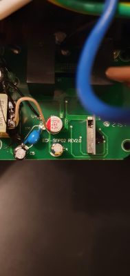
The board marking ECF-SOP02 gives several results, including an FCC ID certification and a US style plug here:
https://expo.tuya.com/product/346445
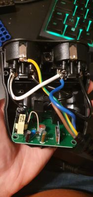
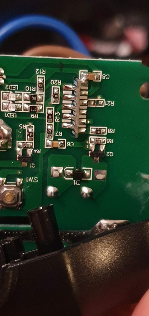
Teardown: The device is closed with five triwing T2 security screws. The fifth one is so deep you can not reach it with bits, you need a narrow driver to get to it. You can also drill the opening a but with an 8mm drill bit, which will break the connection between the lid and the plastic around the screw allowing you to open it. You can then remove the four screws holding the board down, and you will see this:
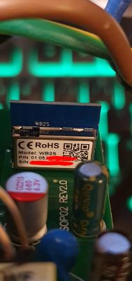
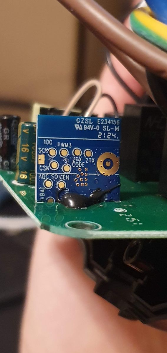
Close up of the chip, front, back and bottom:

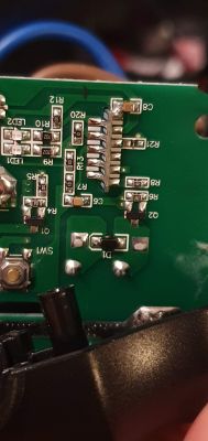
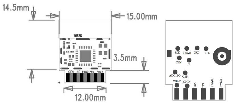
The pin out of the WB2S chip is available underneath the main PCB, and the pads on each side is staggered, so you can easily connect to the pins with some
Test hook clips without soldering. Ok, it's not
easily done, it's a bit fiddly, but can be done with no soldering. Looking back, soldering probably would have gone quicker. But i digress.
You can use this pinout to find the right pins:

3.3v goes to vbat, ground to gnd, and 1rx and 1tx are for rx and tx.
NOTE: I don't remember if you need to switch out rx and tx (ue, connect the programmers tx to 1RX and RX to 1TX. I switched a bit around while connecting. So try to switch them up if you have problems
NOTE2: My programmer apparently does not supply enough power on the 3.3v pin. So I powered the chip with a separate DC power source set to 3.4v
NOTE 3: I stumbled upon
this bug (I believe) while flashing with uartprogram, even if it should be fixed. If you do too, set the baud rate manually with the -b option.
NOTE4: I did not know about tuya-cloudcutter befora I flashed the new firmware. You can maybe save yourself a lot of hassle by flashing this without even opening the device up! You should try this first:
https://github.com/openshwprojects/OpenBK7231T_App/wiki/tuya-cloudcutter-flashing
Ok, so lastly, when you're all set up, which pin is which?
Here you go:
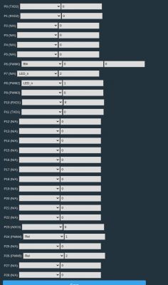
edit: Updated pin config, mistakenly uploaded an old file which was not quite correct. As p.kaczmarek2 mentiones in the post below, you can set the button to control the different relays on single and double click, I had already set this with rules.
Note: I'd like to have the button control both relays via single or double press, but there is no available documentation that tells me how this can be done yet. If someone knows how this could be set up in a nice configurable way, please let me know. Like this setup I have on another device using esphome:
binary_sensor:
- platform: gpio
  pin:
    number: GPIO13
    mode: INPUT_PULLUP
    inverted: True
    # ...
  on_multi_click:
    - timing:
      - ON for at most 0.4s
      - OFF for at least 0.2s
      then:
      - logger.log: "Single-Clicked"
      - switch.toggle: grelay3
    - timing:
      - ON for at most 0.4s
      - OFF for at most 0.5s
      - ON for at most 0.4s
      - OFF for at least 0.3s
      then:
      - logger.log: "Double-Clicked"
      - switch.toggle: grelay2


Comments
Hello, thank you for a very detailed presentation. This. Many users have issues because of low quality/low power 3.3V source. I always recommend the schematic as in our Elektroda video: https://obrazki.elektroda.pl/9129317700_1669654851_thumb.jpg... [Read more]
It is. I think I could accomplish the same thing I outlined above on ESP the same way, for devices with more than two outlets, but I'll need to look into it. The logic would be: On button press increase... [Read more]