logo elektroda
logo elektroda
X
logo elektroda
Dostępna jest polska wersja

Czy wolisz polską wersję strony elektroda?

Nie, dziękuję Przekieruj mnie tam

[CBLC9/BK7231N] RTX WCM1MR roller shutter controller with GPIO output

p.kaczmarek2  4 4434 Cool? (+7)
📢 Listen (AI):

TL;DR

  • RTX WCM1MR roller shutter controller with WiFi and RF input is opened, mapped, and prepared for OpenBeken flashing to break Tuya cloud dependence and integrate with Home Assistant.
  • The CBLC9 BK7231N module uses two relays for up/down motion, while P7 and P9 drive them through Q1/Q2 and P26, P6, P24, and P8 handle inputs and LED.
  • The unit cost about 70 PLN, and the RF connector exposes RX1, GND, and 3.3V, giving an extra lead for a DHT11 or similar sensor.
  • Flashing required desoldering the CBLC9 module, but OpenBeken uploaded successfully and the module was resoldered back into place.
  • Blind calibration and scripting are left for later, and the non-isolated power supply makes attaching peripherals during operation potentially lethal.
Generated by the language model.

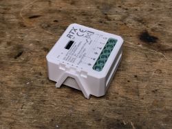
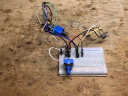
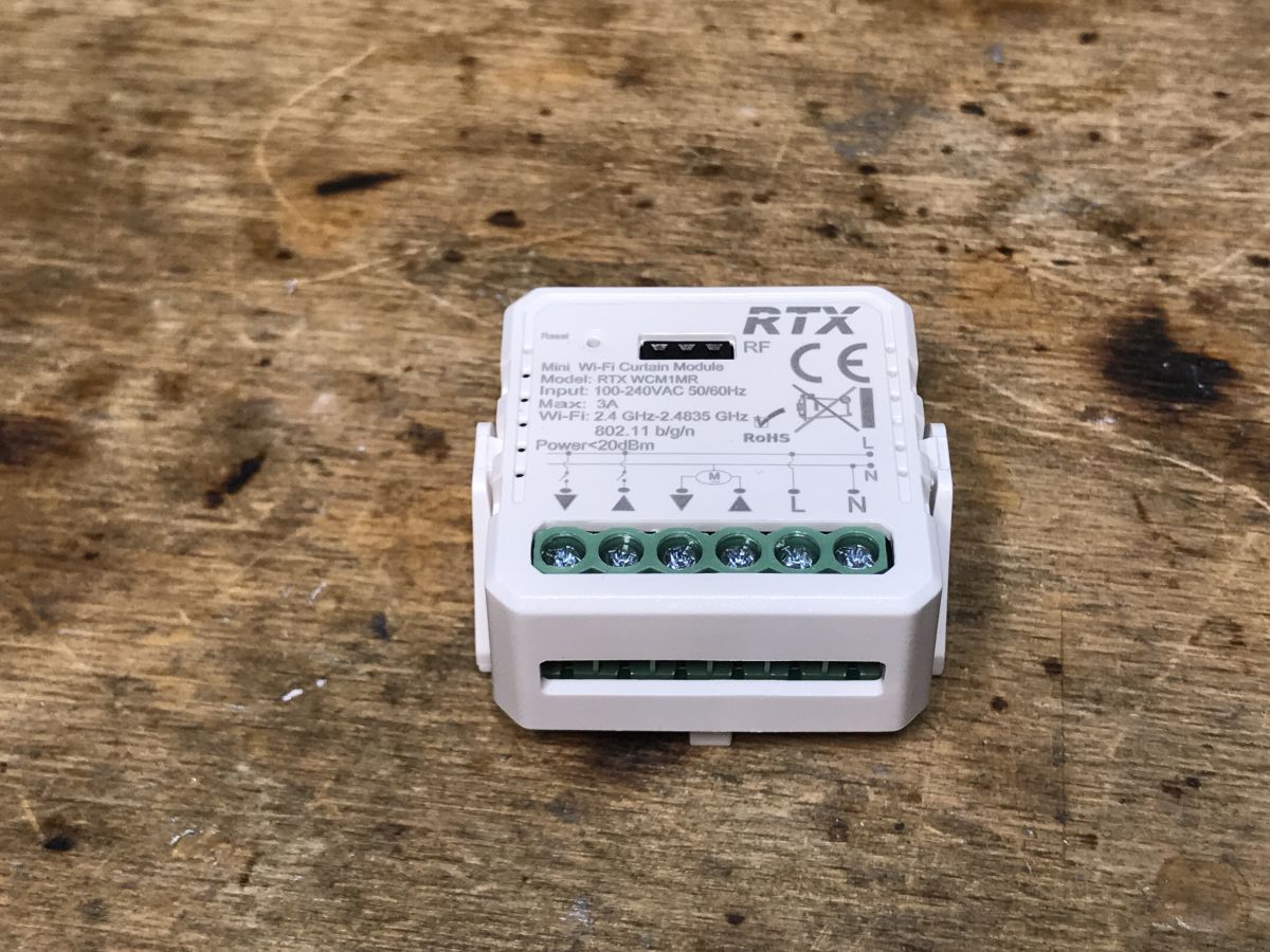
I invite you to a brief description of the interior and firmware changes of the RTX WCM1MR roller shutter controller, bought from a Polish mail order shop for about 70 PLN. Here I will discuss how to conveniently access the RX/TX pads of the CBLC9 WiFi module from the inside and show how to upload OpenBeken to it in order to free it from the cloud and connect it to Home Assistant. Due to the lack of blinds to test, I'll leave the blind calibration and scripting itself for later. If anything, I can always recommend you a topic on roller shutters developed by our US user, available here:
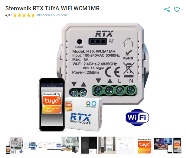
https://www.elektroda.pl/rtvforum/topic3972935.html

Purchase RTX TUYA WiFi WCM1MR
I got the product from a reader to change the batch, Below is a screenshot from the auction:

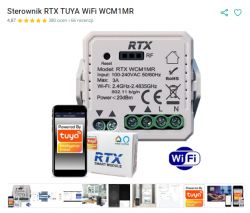
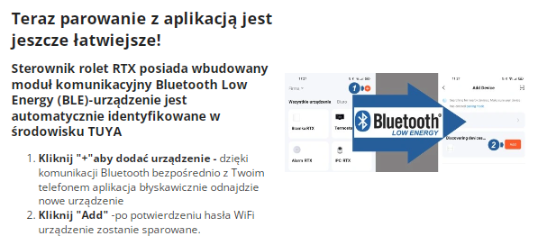
The product features the ability to plug in RF control, there is a connector on the casing for this. Apart from this, there is only WiFi. The product is realised on the BK7231, as evidenced by the information about Bluetooth pairing (but only pairing, not control) provided by the seller:

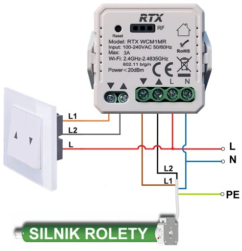
This is the connection diagram:

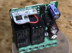
The control of the roller shutter is simple - there are two relays, they cannot both let off current at the same time, switching on one makes the roller shutter go up, in turn the other is responsible for making it go down. The times at which the roller shutter opens/closes are configurable. The application can track to what extent it has already opened the roller shutter.


Contents of the kit
Will there at least still be fixings in the kit this time? No, there is only the relay itself, no screws:

Unfortunately there is not even anything to comment on here.

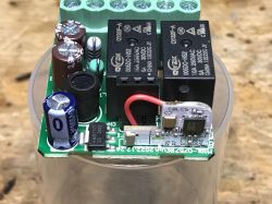
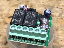
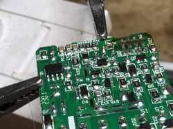
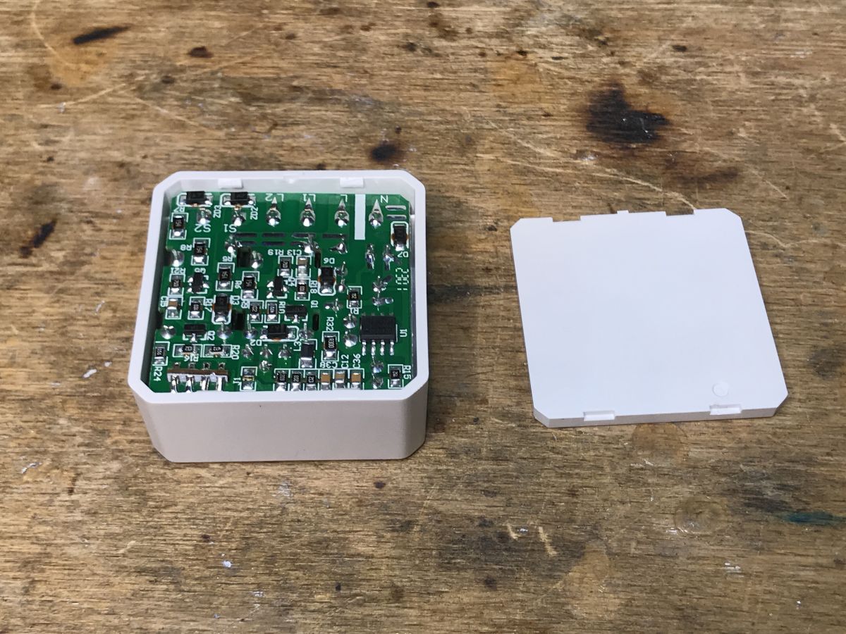
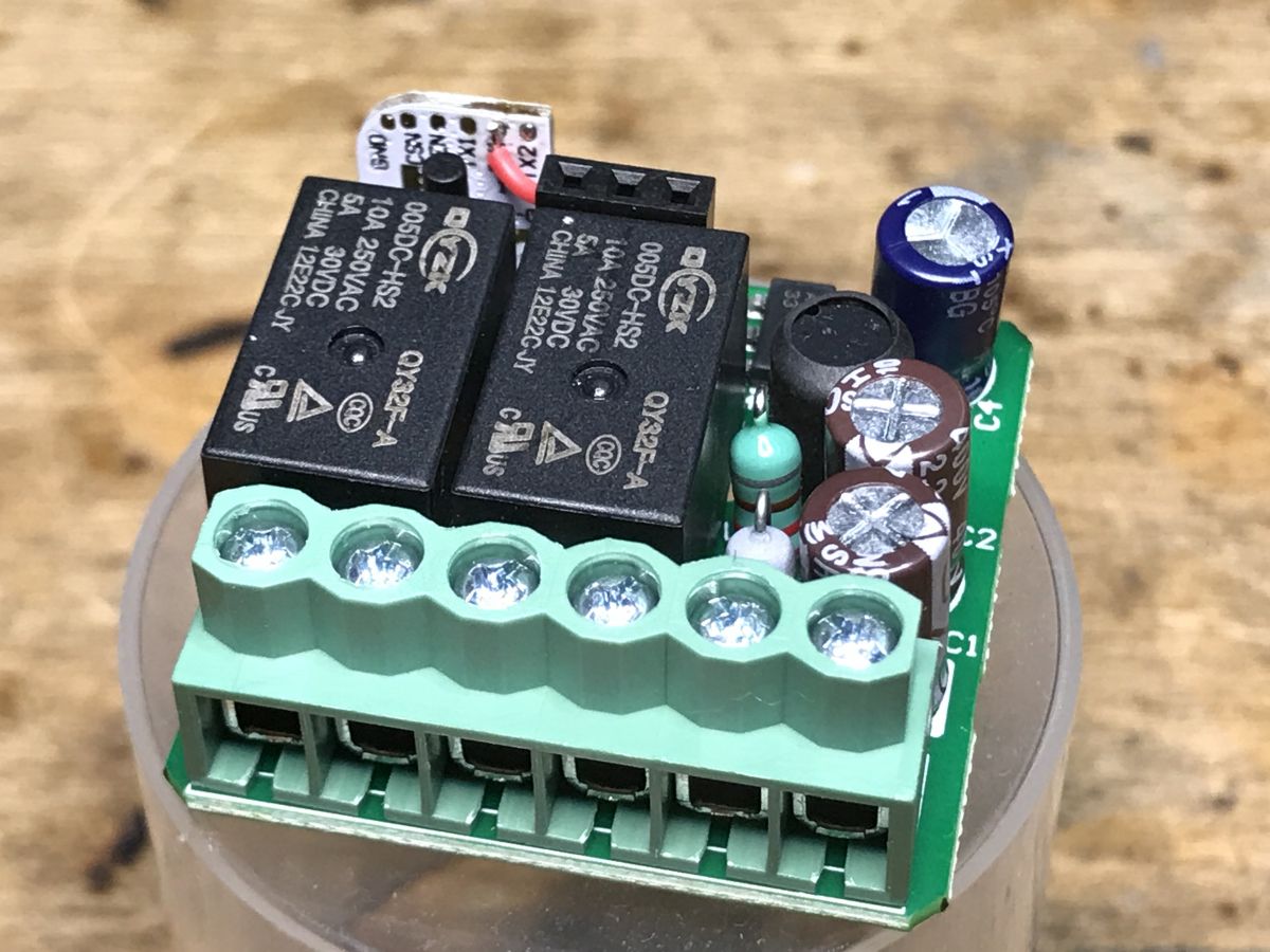
Inside of the controller Undo the cover with a screwdriver and look inside.

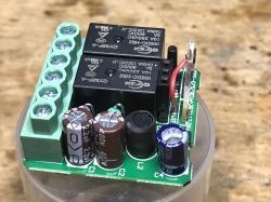
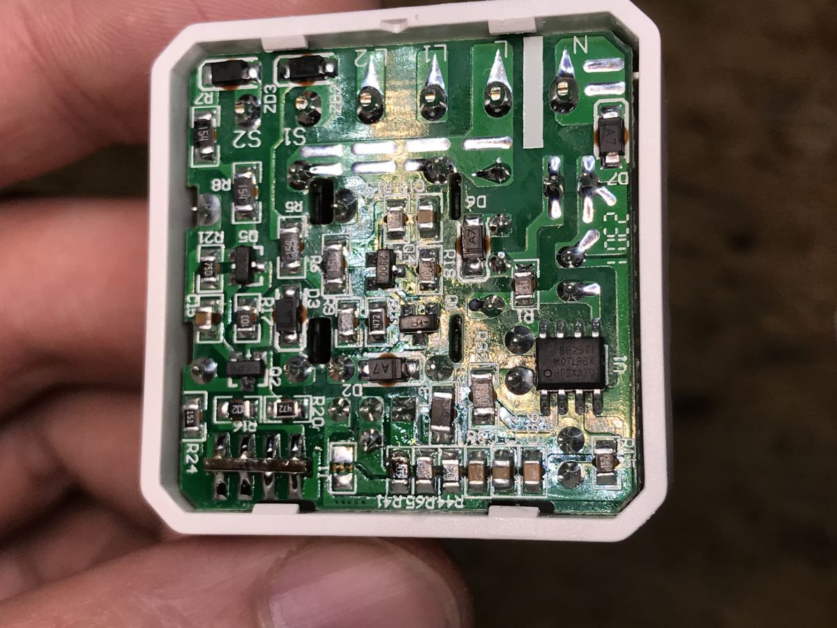
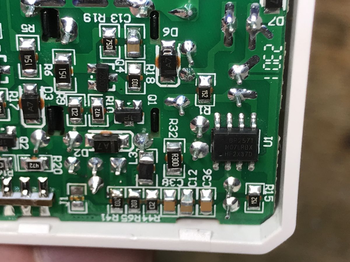
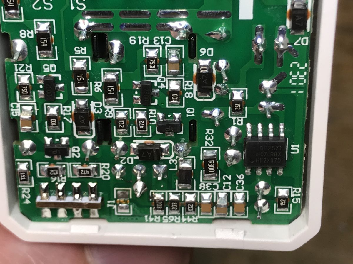
Bottom of the PCB - what is responsible for the power supply?
As far as I can see this is a BP2571, am I reading this right? Probably a step down inverter again.
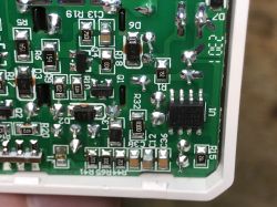
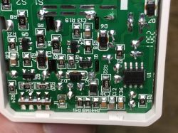
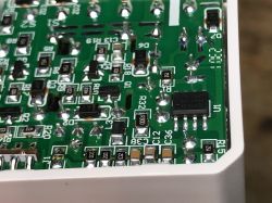
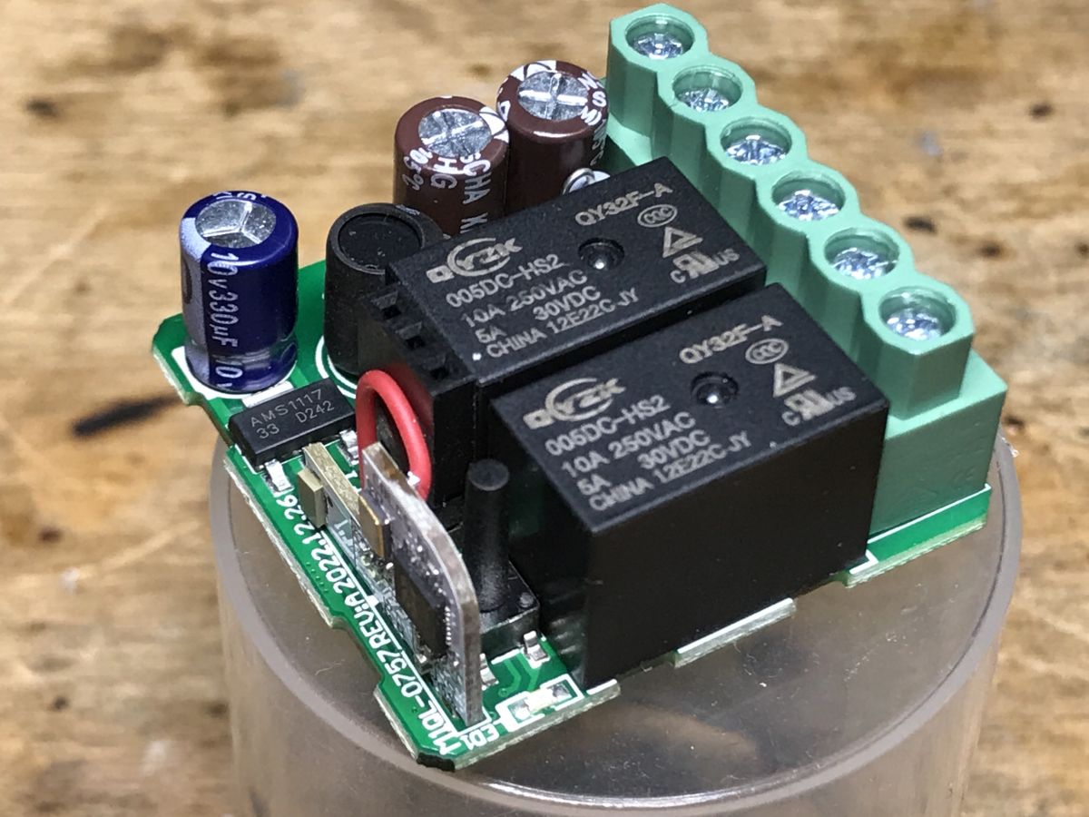
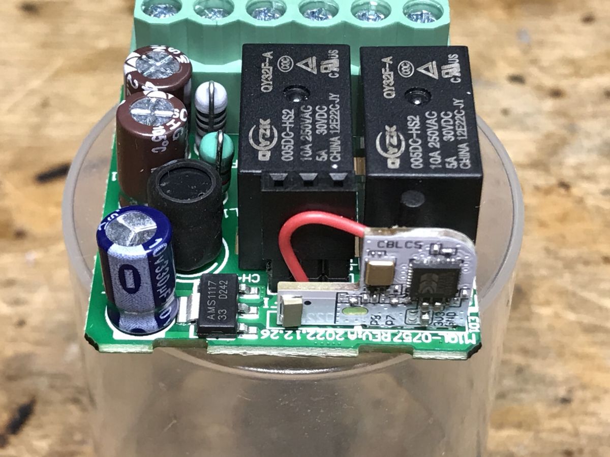
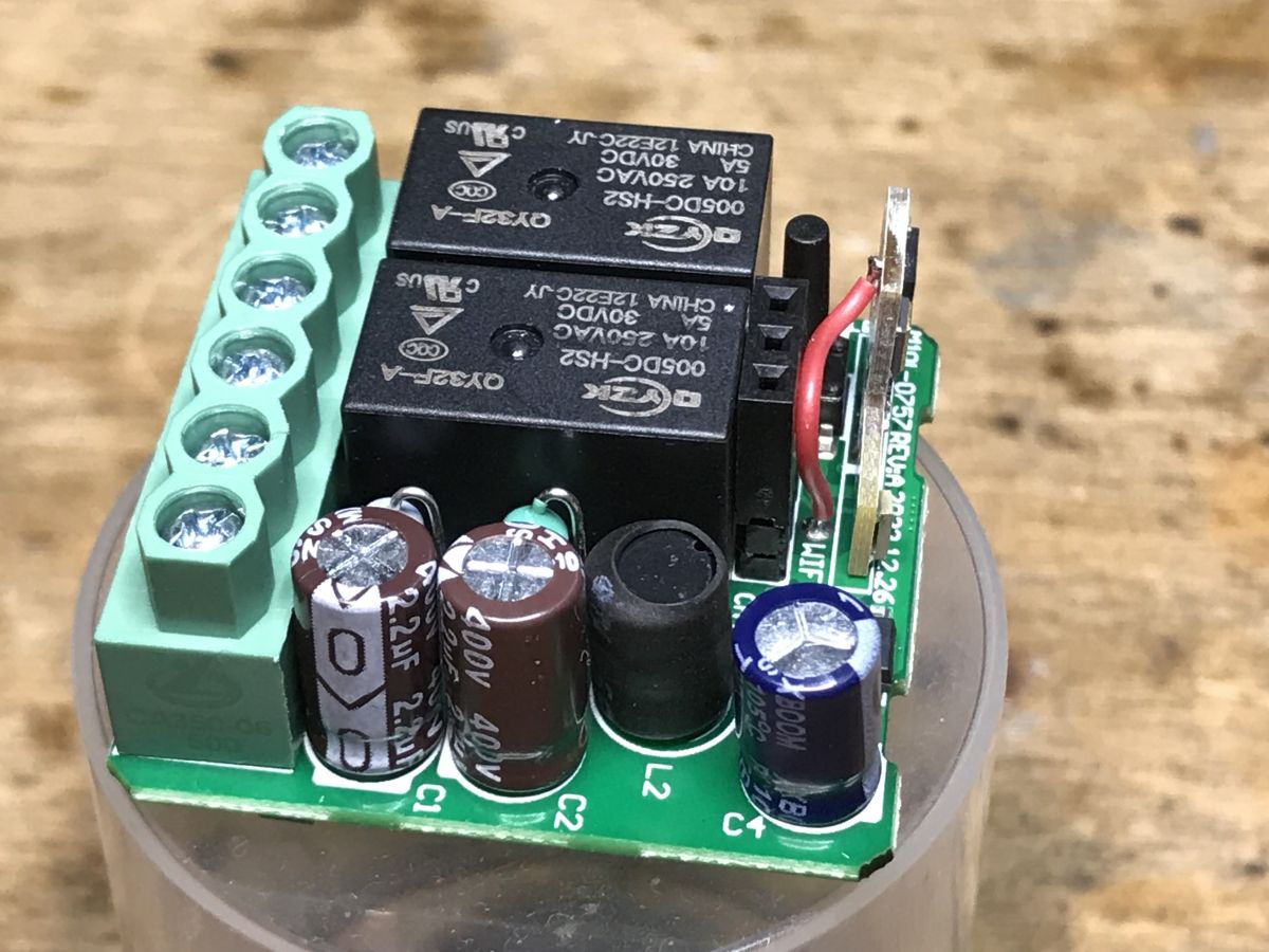
Now the top view:
. .
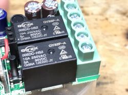
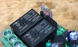
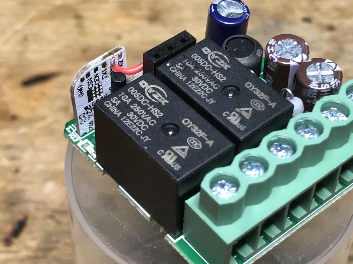
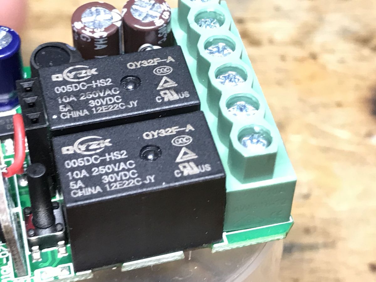
On top you can see two 005DC-HS2 relays, part of the power supply circuit (there is also a fuse resistor), the LDO AMS1117-3.3V stabilizer, and, well, the WiFi module...
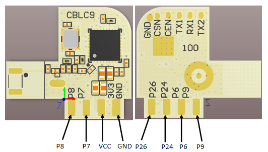
What is the WiFi module?

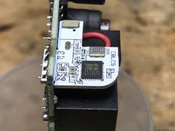
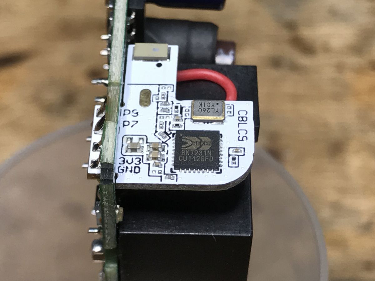
CBLC9, which is a module based on BK7231N.

Pin number Symbol I/O type Function
1 P9 I/O Support hardware PWM and correspond to P9 on the internal IC
2 P8 I/O Common I/O pin and correspond to P8 on the internal IC
3 P6 I/O Support hardware PWM and correspond to P6 on the internal IC
4 P7 I/O Support hardware PWM and correspond to P7 on the internal IC
5 P24 I/O Support hardware PWM and correspond to P24 on the internal IC
6 VCC P Power supply pin (3.3V)
7 P26 I/O Support hardware PWM and correspond to P26 on the internal IC
8 GND P Power supply reference ground
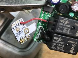
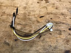
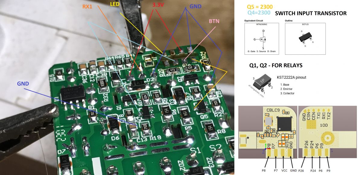
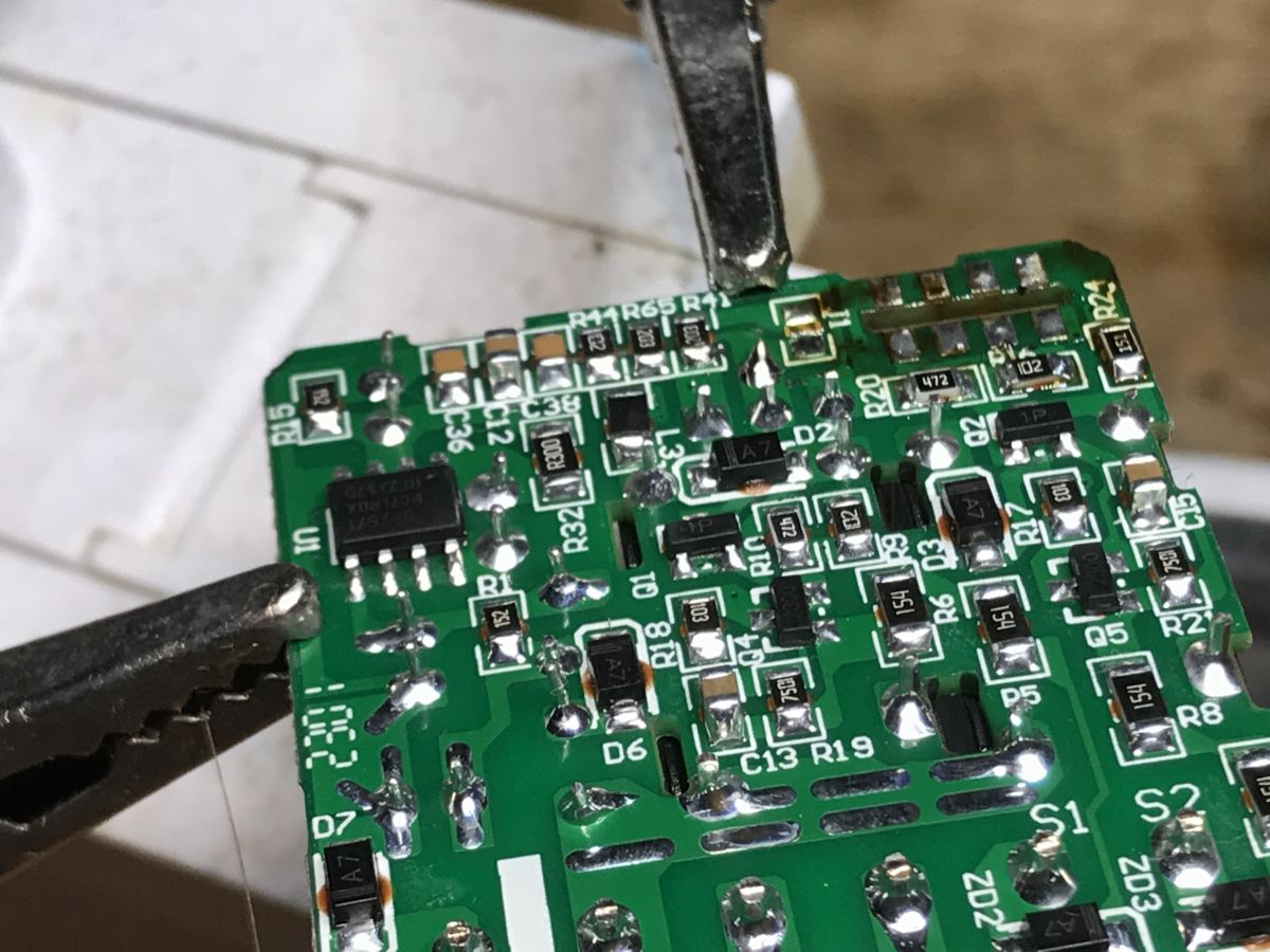
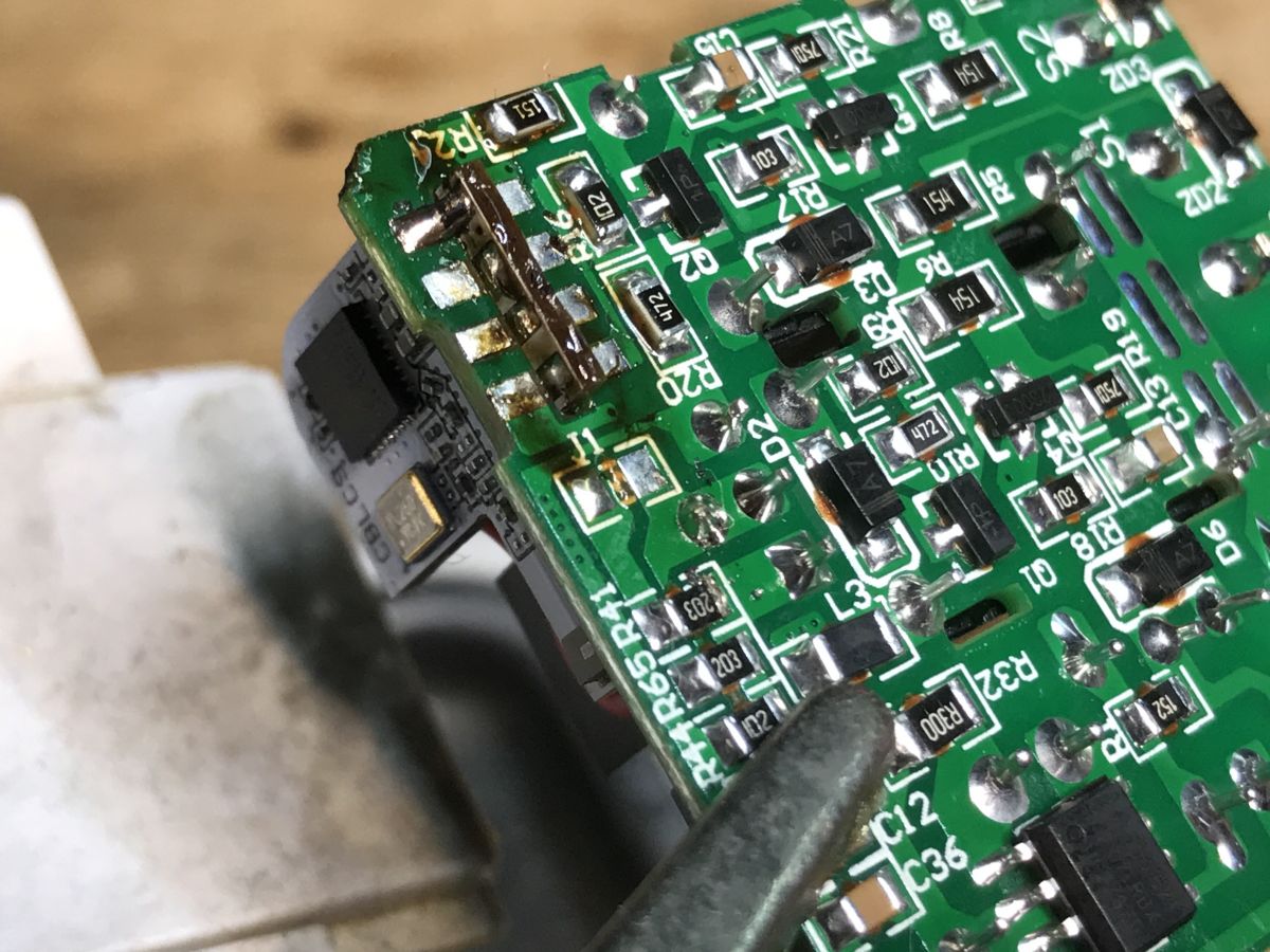
This module has programming pads on the back, slightly covered here. In addition, there is a cable soldered wildly to RX1, we will see what it is for shortly.
I soldered the module and did a PCB analysis:
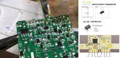
The RF connector has RX1, ground and 3.3V.
Buttons from the roller shutter control are connected via resistors and diodes to the bases of Q5 and Q4 (2300), in turn the status on their drains are tested by P26 and P6. The pairing button is on P24, the LED is on P8. The other two GPIOs, P7 and P9 handle the relays, controlling them via Q1 and Q2.
The OpenBeken template can be made based on this :
Code: JSON
Log in, to see the code

Project repository: https://github.com/openshwprojects/OpenBK7231T_App
List of supported devices: https://openbekeniot.github.io/webapp/devicesList.html

Change firmware The easiest way is to solder out the whole WiFi module and use my tool for programming, instructions on the repository:
https://github.com/openshwprojects/BK7231GUIFlashTool
I apply flux, remove the bond with a braid and the module falls out of the PCB by itself. Here I still have to desolder the RF cable.

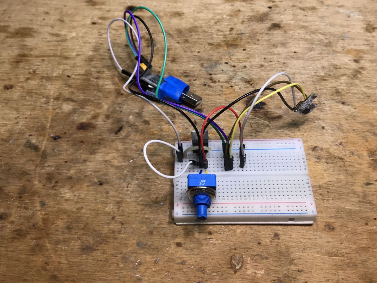
I connect only RX and TX, ground and 3.3V (I have an LDO on the pin) and this is enough to upload the batch:
Then the module goes back politely into place (I catch one pad with a solder, then solder the others):


. Summary
Changing the batch requires soldering out the CBLC9 module, but this is not difficult at all. An extra RF slot leads to the RX1 pin, this can be used, e.g. by connecting DHT11 or another sensor (we just happen to have 3.3V, GND and one GPIO lead out, just in time!), all this OpenBeken already supports, you just have to remember here that the power supply used in this product does not provide galvanic separation, so any playing around with it and connecting peripherals to it during operation can be deadly. As for just getting the roller shutters up and running and connecting them to the Home Assistant, I refer you to the usual topic below:
https://www.elektroda.pl/rtvforum/topic3972935.html

About Author
p.kaczmarek2
p.kaczmarek2 wrote 14622 posts with rating 12638 , helped 655 times. Been with us since 2014 year.

Comments

bsw 22 Nov 2024 08:40

. The RF socket is originally designed for mounting the wireless radio remote control module: https://obrazki.elektroda.pl/6611585900_1732261148_thumb.jpg https://obrazki.elektroda.pl/8045194400_1732261156_thumb.jpg... [Read more]

p.kaczmarek2 22 Nov 2024 08:54

What you are talking about was stated at the beginning of the topic, before the firmware change: . Thank you for showing a pic of what it looks like. After the firmware change, as I wrote, the socket... [Read more]

vincenzoernst1 07 Aug 2025 20:47

@pkaczmarek2 how do we add oem devices to the template list? this one is the same as the one i postet under the name QS-WIFI-ECC02 , but without the gpio header [Read more]

p.kaczmarek2 07 Aug 2025 21:12

Add your template here (with full info, image link to Elektroda, topic link, etc) and open pull request: https://github.com/OpenBekenIOT/webapp/blob/gh-pages/devices.json [Read more]

FAQ

TL;DR: For a 70 PLN RTX WCM1MR, “desolder the CBLC9 module” to flash OpenBeken, then use 6 mapped GPIOs for relays, buttons and LED. This FAQ helps smart-home modders free BK7231N shutter controllers from Tuya cloud and reuse the RF socket safely. [#20603398] Why it matters: Local OpenBeken control makes the RTX WCM1MR practical for Home Assistant while exposing a real electrical-safety limitation.

Option Control path Local operation Hardware note
Tuya firmware WiFi cloud plus optional RF module No Original firmware and RF accessory socket
OpenBeken Local firmware with Home Assistant integration Yes Requires CBLC9/BK7231N flashing
RF socket reuse 3.3 V, GND and RX1 GPIO Yes, after OpenBeken Suitable for supported sensors only

Key insight: The RF connector is not only for the original radio module. After OpenBeken, it exposes 3.3 V, GND and one GPIO, but the internal power supply has no galvanic isolation.

Quick Facts

  • The RTX WCM1MR discussed cost about 70 PLN and shipped as the relay unit only, without screws or fixings. [#20603398]
  • The controller uses 2 relays: one drives shutter opening and the other drives closing, and both must not energise together. [#20603398]
  • The WiFi board is CBLC9, a BK7231N-based module with 3.3 V VCC and GND pins shown in the pin table. [#20603398]
  • OpenBeken mapping uses 6 GPIO assignments: P6 button, P7 relay, P8 inverted WiFi LED, P9 relay, P24 button and P26 button. [#20603398]
  • The RF socket is intended for a wireless radio remote module, but after firmware replacement it can carry sensors such as DHT, IR receiver or DS18B20. [#21313787]

How do I flash OpenBeken onto an RTX WCM1MR roller shutter controller with a CBLC9/BK7231N module?

Desolder the CBLC9 module, wire UART power and data, then flash it with BK7231GUIFlashTool.
  1. Apply flux and remove solder with braid until the module releases.
  2. Connect RX, TX, GND and 3.3 V to the programmer.
  3. Upload OpenBeken, then solder the module back onto the PCB. The thread used only 4 programming connections: RX, TX, ground and 3.3 V. [#20603398]

What is the CBLC9 WiFi module used in the RTX WCM1MR, and how is it related to the BK7231N chip?

The CBLC9 is the RTX WCM1MR WiFi module, and it is based on the BK7231N chip. "CBLC9 is a WiFi module that hosts the BK7231N microcontroller, exposes 3.3 V power, GND and GPIO pins, and provides the wireless logic used by the RTX WCM1MR controller." Its pin table includes P6, P7, P8, P9, P24 and P26. [#20603398]

Which GPIO pins control the relays, buttons, and LED on the RTX WCM1MR shutter controller after flashing OpenBeken?

Use P7 and P9 for relays, P6, P24 and P26 for buttons, and P8 for the inverted WiFi LED. The OpenBeken template maps pin 6 to Btn;1, pin 7 to Rel;1, pin 8 to WifiLED_n;0, pin 9 to Rel;2, pin 24 to Btn;3 and pin 26 to Btn;2. That gives 6 functional GPIO assignments. [#20603398]

How can I access the RX and TX pads on the CBLC9 module inside the RTX WCM1MR?

Access RX and TX most conveniently by desoldering the whole CBLC9 module from the RTX WCM1MR PCB. The programming pads sit on the back of the module and are partly covered in the assembled controller. After removal, connect RX, TX, GND and 3.3 V. The author also had to desolder the RF cable before programming. [#20603398]

What OpenBeken template should I use for the RTX WCM1MR roller shutter controller?

Use the RTX WCM1MR Shutter Controller template for a Tuya device with BK7231N chip and CBLC9 board. The template names model WCM1MR, sets flags to 1024, and maps 6 pins. It assigns relays to P7 and P9, buttons to P6, P24 and P26, and WifiLED_n to P8. [#20603398]

How does the RF connector on the RTX WCM1MR work, and what pins does it expose?

The RF connector was designed for an optional wireless radio remote-control module. In the PCB analysis, the connector exposes RX1, ground and 3.3 V. A later photo confirmed that the original accessory is a plug-in radio remote module. After OpenBeken, that same 3-pin socket can become a general low-voltage GPIO connector. [#21313768]

What kinds of sensors can be connected to the RTX WCM1MR RF socket after replacing the Tuya firmware with OpenBeken?

You can connect supported one-wire or single-GPIO peripherals such as DHT sensors, an IR receiver or a DS18B20. The socket provides 3.3 V, GND and one GPIO via RX1, which matches simple 3-pin sensor wiring. The thread explicitly names DHT11, several DHT types, IR receiver support and DS18B20. [#21313787]

What safety precautions are needed when connecting a DHT11, DS18B20, or IR receiver to the RTX WCM1MR RF socket?

Treat every RF-socket peripheral as mains-referenced unless the controller is fully isolated and safe to handle. The device power supply inside is not galvanically isolated. That makes connecting or touching a DHT11, DS18B20 or IR receiver during operation potentially deadly. Work only with power disconnected and maintain enclosure isolation after modification. [#20603398]

What is OpenBeken, and how does it help remove Tuya cloud dependency from BK7231N devices?

OpenBeken is replacement firmware for BK7231 devices that enables local control without Tuya cloud dependence. "OpenBeken is open firmware for BK7231-based IoT modules that replaces vendor cloud firmware, maps device GPIO functions, and exposes local smart-home integration features." In this RTX WCM1MR case, it lets the shutter controller connect to Home Assistant after flashing. [#20603398]

What is Home Assistant, and how can it be used with an OpenBeken-based roller shutter controller?

Home Assistant is the local smart-home platform targeted after installing OpenBeken on the RTX WCM1MR. The thread states that flashing OpenBeken frees the controller from the cloud and connects it to Home Assistant. The controller still needs shutter calibration and scripting, because the author had no blinds available to test those settings. [#20603398]

OpenBeken vs Tuya cloud firmware — which is better for controlling RTX WCM1MR roller shutters locally?

OpenBeken is better when the goal is local RTX WCM1MR shutter control without Tuya cloud. The Tuya firmware offers WiFi operation and optional RF control, while OpenBeken replaces cloud dependence and supports Home Assistant integration. The trade-off is hardware work: the CBLC9 module must be flashed, and calibration still needs setup. [#20603398]

How do I configure roller shutter opening and closing times in OpenBeken for Home Assistant integration?

Set opening and closing times after flashing, but this thread does not provide the final calibration script. The original controller supports configurable open and close times and can track shutter position. The author explicitly postponed blind calibration because no shutters were available for testing, and referred readers to a separate shutter topic. [#20603398]

What is the BP2571 power supply chip mentioned in the RTX WCM1MR teardown, and what role does it play?

The BP2571 is identified as part of the RTX WCM1MR power-supply section. "BP2571 is a power-supply IC observed on the controller PCB that appears in the mains conversion stage, feeding downstream low-voltage circuitry alongside parts such as the AMS1117-3.3 V regulator." The author read the marking as BP2571 and described it as likely step-down circuitry. [#20603398]

How do I add an OEM device template such as QS-WIFI-ECC02 or RTX WCM1MR to the OpenBeken devices list?

Add the full device template to the OpenBeken webapp devices.json file and open a pull request. Include complete information, an Elektroda image link and the topic link. This was the requested route for an OEM device such as QS-WIFI-ECC02, described as similar to this controller but without the GPIO header. [#21628780]

What troubleshooting steps help when BK7231GUIFlashTool cannot flash a desoldered CBLC9/BK7231N module?

Check the 4 required connections first: RX, TX, GND and 3.3 V. If flashing still fails, swap RX and TX, verify the 3.3 V supply, and inspect solder pads for leftover braid damage or bridges. The thread’s successful setup used a desoldered CBLC9 module and only those 4 wires for programming. [#20603398]
Generated by the language model.
%}