[CBU/BK7231N] Template/GPIO for Milfra Tuya WiFi Light Switches (2-gang and 3-gang)
I bought 2-gang and 3-gang Milfra Tuya WiFi Light Switches from the link below.
https://www.aliexpress.com/item/1005006285609205.html
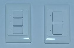
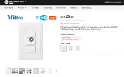
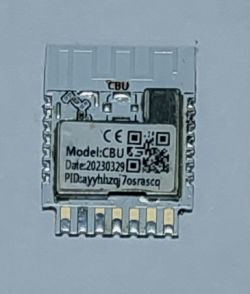
Both of the 2-gang and 3-gang switches have CBU modules in the photo below.
The PCBs for the two switches are exactly the same as in the photo below.
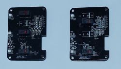
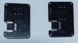
For the 2-gang switch, K1=K5 (see the labels on the PCBs). Therefore, K5 is switch1, and K3 is switch2.
The same applies to the relays. relay1 (3-gang)-> relay1 (2-gang), relay3 (3-gang)->relay2 (2-gang)
The pin roles are as follows.
3-gang switch
P7: Button1
P8: Button2
P14: Relay1
P16: Relay2
P20: Relay3
P24: WIFI_LED
P28: Button3
2-gang switch
P7: Button1
P14: Relay1
P20: Relay2
P24: WIFI_LED
P28: Button2
I eventually replaced the CBU module with ESP8685-WROOM-06 Module, which requires some modding due to differences in pinouts.
FYI, when the CBU module is replaced with the ESP8685-WROOM-06 Module, pin #3 (P20 for CBU and NC for ESP8685) used for relay3 and pin #17 (P28 for CBU and NC for ESP8685) used for button3 must be connected to other GPIOs because pin #3 and pin #17 of ESP8685 have no connection (NC).
I soldered jumper wires from pin #3 to GPIO6 (pin #10) and from pin #17 to GPIO10 (pin #19).
I hope this helps.
https://www.aliexpress.com/item/1005006285609205.html


Both of the 2-gang and 3-gang switches have CBU modules in the photo below.

The PCBs for the two switches are exactly the same as in the photo below.


For the 2-gang switch, K1=K5 (see the labels on the PCBs). Therefore, K5 is switch1, and K3 is switch2.
The same applies to the relays. relay1 (3-gang)-> relay1 (2-gang), relay3 (3-gang)->relay2 (2-gang)
The pin roles are as follows.
3-gang switch
P7: Button1
P8: Button2
P14: Relay1
P16: Relay2
P20: Relay3
P24: WIFI_LED
P28: Button3
2-gang switch
P7: Button1
P14: Relay1
P20: Relay2
P24: WIFI_LED
P28: Button2
I eventually replaced the CBU module with ESP8685-WROOM-06 Module, which requires some modding due to differences in pinouts.
FYI, when the CBU module is replaced with the ESP8685-WROOM-06 Module, pin #3 (P20 for CBU and NC for ESP8685) used for relay3 and pin #17 (P28 for CBU and NC for ESP8685) used for button3 must be connected to other GPIOs because pin #3 and pin #17 of ESP8685 have no connection (NC).
I soldered jumper wires from pin #3 to GPIO6 (pin #10) and from pin #17 to GPIO10 (pin #19).
I hope this helps.


Comments
Any reason why some of the pins have no connection? I just thought it’s odd they purposely designed it that way https://obrazki.elektroda.pl/7547230400_1701510701_thumb.jpg [Read more]
ESP8685-WROOM-06 is based on ESP32C3 chip. According to the datasheet, ESP32C3 has 22 or 16 programmable GPIOs. It seems that only 16 GPIOs are utilized (ESP8685-WROOM-06 has 15 GPIOs including RX and... [Read more]