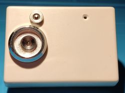
Miniature electronic lock with 1WIRE systems

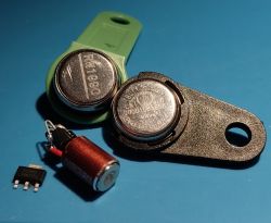
The miniature electronic lock with 1WIRE systems described below, unlike hundreds of similar projects, has a specific feature: it works not only with DALLAS DS1990 or RW1990 systems, but basically with any system with a 1WIRE interface having its own unique ROM address.
Apart from the DS1990/RW1990 chips, I had several DS2405 chips in my drawer and I had no idea what I could use them for. Similarly with used, worn-out DS18B20 systems, which for some reason did not measure the temperature correctly.
The common feature of these chips is the interface and their own address, consisting of the "family" code, serial number and CRC.
And that`s how the idea for the unusual 1WIRE lock was born.
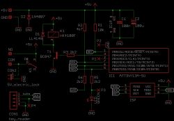
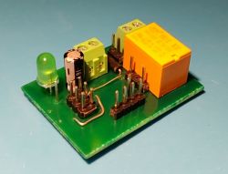
The presented lock is not some innovative electronic design: attiny13, goldpins - as a 6-pin KANDA programming socket, - a chip reader (4-pin version), a miniature 5V relay switching on the bolt, electric strike or electromagnetic lock (whatever you call it) and an LED diode.
The system is powered directly from the 5V/1.5A power supply, because the model uses an electric strike with a 5V coil (the diode eliminating overvoltages is connected directly to its coil, not on the board).
The dashed line in the diagram shows the connection of the NO contact to +5V and the COM contact of the relay to pin 1 of the CON2 socket for connecting the electric strike coil.
If a 12V or other coil is used, cut the connections marked with an X on the printed circuit board and use the "clean" relay contact available on the NO and COM connector terminals. If the system and coil are powered by 5V, it is worth increasing the capacity of C2.

The program was written in ARDUINO for ATTINY13 using the MicroCore library, which must be installed. Library description available at https://github.com/MCUdude/MicroCore. Arduino settings in the attachment.
If I`m not mistaken, the factory new attiny13 has clock division by 8 (CKDIV8) enabled, so it should be disabled because the program should be compiled for a 9.6MHz clock. The remaining fusebits can be left unchanged.
In the sketch in place: byte table_serialNumbers[][8] = { }; please enter your own serial numbers of 1WIRE systems. For this purpose, an additional simple sketch was created, reading these numbers in the Arduino terminal. The "data" pin of the read system should be connected to pin 2 of Arduino.
and in place: int numSerialNumbers = 4; enter the number of entered numbers so that the number matches the number given in the table above. There can be one, but no more than 4.
This may not be an elegant solution - the system does not "learn" how to save key numbers - but it simplifies the program, especially if the author is not an advanced programmer.
Pin "3" of Arduino determines the time of switching on the relay, and thus the electric strike. If pin "3" is not shorted to ground, this time is 3s. When this pin is shorted to ground (points P1 and P2 connected) - the switch-on time will be 1 s.
In this way, you can control the bolt, which is triggered by an impulse, just like in the video. Of course, these times can be changed according to your own preferences.
The reader`s LED lights up for the duration of relay operation, and an additional LED on the printed circuit board flashes in standby mode. You can omit the LED on the PCB and the R6 resistor and use the reader`s LED and connect points P3 and P4.
Then the reader`s diode will flash in standby mode, which will make it easier to approach the tablet when it is e.g. dark.

In addition to the chip reader, it was necessary to come up with a socket/plug for other 1Wire systems.
And here a magnetic cable for charging the phone came to the rescue... or rather, it provided the plug and socket. 1Wire systems can be powered parasitely via the data line, i.e. using 2 wires.

Just connect the Vdd and GND pins connected together to ground (for DS2405 it`s PIO and GND), and the DATA (Dq) pin is the data line.
Since there is usually an LED in such a plug that takes energy to power the 1Wire system, it was necessary to connect the plug the other way around (data line on the housing) so that the plug`s LED would not light up.
The socket was connected to the PCB using a "micro USB breadboard socket".
Pay attention to the load capacity of the contacts of the relay used and the power of the bolt used.
The attachment includes, among others:
- Arduino sketch of the lock
- Arduino sketch for reading serial numbers
- EAGLE files: sch and brd


Comments