[CBU/BK7231N] AVATTO WSM16-W1 WiFi relay module for PLN 30 - firmware change
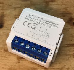
Today we are modifying another relay module for the box so that it works 100% locally, regardless of the manufacturer`s servers. Then we will also pair it with Home Assistant. This modification was made for a reader who sent me a set of gadgets that I haven`t described yet so that we could expand our electrode list of IoT device interiors .
Purchase of WSM16-W1
The module was purchased quite cheaply - less than PLN 30:
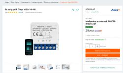
The description has standard Tuya talk:
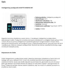
What also catches my eye is that the description includes the version 250W and we got the versions 800W , I wonder if both versions have the same interior?
Parameters:
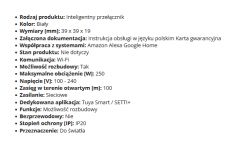
Packaging:
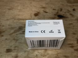
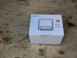
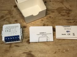
The contents of the set (well, there is a plastic mounting with hooks):
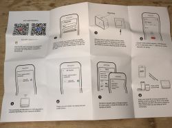
Instruction:
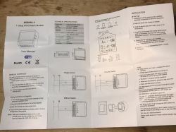
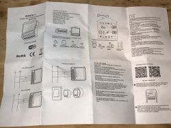
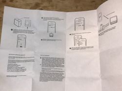
Interior of WSM16-W1
We question the casing:
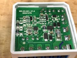
Inside there is again a non-isolated converter based on OB2525. I also see a fuse resistor and a step down converter (U2), because OB2525 only provides 5V, and I need to generate another 3.3V for the WiFi module:
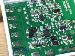
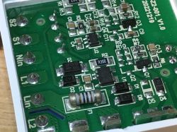
In this case, it was extremely difficult to remove the PCB from the other half of the housing. I had to gradually pry from each side.
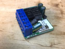
Inside is the CBU module:
https://developer.tuya.com/en/docs/iot/cbu-module-datasheet?id=Ka07pykl5dk4u
You can upload:
https://github.com/openshwprojects/OpenBK7231T_App
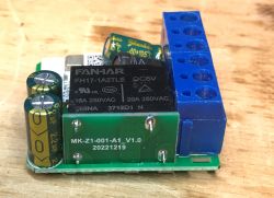
The whole thing is packed very tightly, the capacitor and the coil are specially placed:
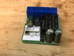
In order to reduce the thickness of the module, the clever manufacturer placed the relay on its side:
Changing the WSM16-W1 load
According to the readme of our flasher:
https://github.com/openshwprojects/BK7231GUIFlashTool
You can also check out the Elektroda channel, there are flashing video tutorials:
https://www.youtube.com/watch?v=Yb3zXtBdSnE&list=PLzbXEc2ebpH0CZDbczAXT94BuSGrd_GoM&index=7
CBU documentation is available online:
https://developer.tuya.com/en/docs/iot/cbu-module-datasheet?id=Ka07pykl5dk4u
We solder four wires, first whiten the pads:
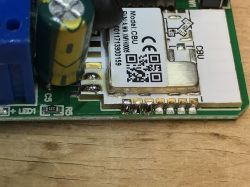
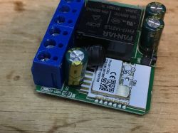
Soldered:
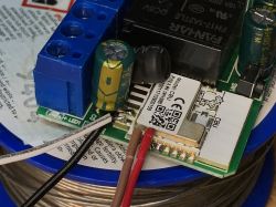
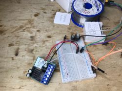
Whole flashing system:
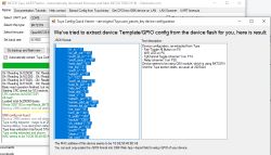
Flasher correctly detects Tuya configuration:
JSON:
Code: JSON
Verbal description:
Device configuration, as extracted from Tuya:
- Pair/Toggle All Button on P8
- WiFi LED on P6
- TglChannelToggle (channel 1) on P14
- Relay (channel 1) on P20
Device seems to be using CBU module, which is using BK7231N.
And the Tuya section starts, as usual, at 2023424
OBK template:
Code: JSON
Uploading a template:
Configuration with HA:
This device probably needs to be entered as well PowerSave 1 to short startup command, otherwise we will have to replace the capacitor after a few months, as in this topic: https://www.elektroda.pl/rtvforum/topic3898805.html
Summary
The manufacturer has made every effort to pack this module into a small housing. Even the relay was specially mounted "on the side", so as not to increase the height of the module. Similarly with the coil and capacitor.
Changing the firmware was, as usual, hassle-free, just solder four cables and the configuration was automatically detected by my flasher again.
For such money - I can recommend this module.


Comments
interesting your extraction seems to suggest there's an RF version. I don't see evidence yours have an RF chip "remote_io":"23", [Read more]
Nice finding. I seem to remember that there was some other version of this device around, it had a 3 pin female connector for external RF receiver.... maybe this? https://obrazki.elektroda.pl/4673127300_1765891962_thumb.jpg... [Read more]