[CB3S/BK7231N] SB436 single relay - QS-WIFI-S03 WiFi - change of firmware
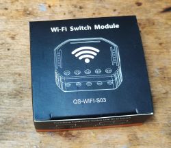
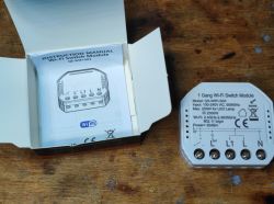 Today we are reworking another WiFi-controlled relay so that it works fully locally, without the manufacturer's servers. The product shown here can be purchased in our country for around £40. It appears under the name QS-WIFI-S03, also sometimes called SB436.
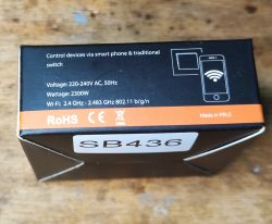
Instruction manual and wiring diagram (to be consulted yourself):

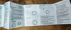
Normally it is for use with the Tuya app, but here I focus on changing the firmware.
Interior of QS-WIFI-S03 Undo the cover:
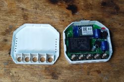
Inside classically - a relay, here an SCH-T76-1A-5S, some fuse resistor and probably a non-isolated step-down converter.
I wonder what happens in place of BE1 - a buzzer?
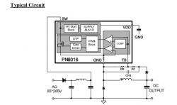 PN8016 generates 5V, separately then further we have LDO 3.3V powering the WiFi module.
Changing the QS-WIFI-S03 firmware
According to our flasher's instructions:
https://github.com/openshwprojects/BK7231GUIFlashTool
We need a USB to UART converter and four cables:
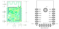
We solder the power supply, RX and TX.
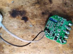
First the power supply:
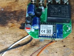
Then the RX and TX:
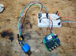
The whole circuit:
Flasher when reading the batch correctly detects the Tuya configuration:
Code: JSON
Can be imported into OBK:
It is also possible to use the importer:
https://openbekeniot.github.io/webapp/templateImporter.html
Word description:
Device seems to be using CB3S module, which is BK7231N chip.
- Relay (channel 1) on P6
- WiFi LED on P8
- TglChannelToggle (channel 1) on P24
- Pair/Toggle All Pin on P9
Template OBK:
Code: JSON
Summary
The conversion was seamless and the flash tool detected the configuration itself. I can recommend this product. The only thing worth remembering is to enable PowerSave 1 on it in OBK (add to autoexec.bat) as these power supplies inside are not very well made and the high current draw could degrade the electrolytic capacitor too quickly. Then the situation from the topic would repeat itself:
How do I fix a smart device that crunches, squeaks and makes strange noises? Other than that - no problems when changing the software, can be recommended.


Comments