Builds a touchscreen RGB lamp controller on an ESP32-2432S028R display that drives Tasmota/OpenBeken devices.
Uses LVGL's color picker, a brightness slider, and on/off button, then sends HTTP GET commands and parses JSON replies.
The lamp status query returned HTTP GET Status = 200 and a 139-byte JSON response with Dimmer, HSBColor, Channel, and POWER fields.
Two-way sync works: brightness and color changes on the native OBK panel update the touchscreen, though the refresh has a small delay.
A limitation is the per-command FreeRTOS task model; a single worker thread would be cleaner and more efficient.
Generated by the language model.
.
Today we are creating another mini project - this time it will be a touchscreen RGB lamp controller. The controller itself will be based on the ESP32 board + ESP32-2432S028R touch display, while it will control any Tasmota/OpenBeken device via Tasmota's HTTP interface. Commands will be sent as GET requests and responses will be parsed from the received JSON format, which the Tasmota documentation discusses in detail:
https://tasmota.github.io/docs/Commands/ https://tasmota.github.io/docs/Commands/#with-web-requests
I've taken the liberty of using the trial version of SquareLine Studio in this topic, but it's essentially redundant here, the RGB controller can be placed from within the code (which SquareLine Studio de facto does), I'll post the code for creating it too.
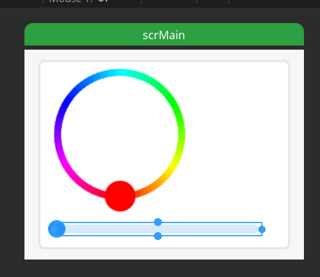
Step 1 - the UI itself .
The whole project is very attractive and beginner-friendly. We have the necessary components ready - even the colour selection widget is already in LVGL, which by the way you can read about in their documentation:
https://docs.lvgl.io/7.11/widgets/cpicker.html In addition, a slider to control the brightness level and maybe an on/off button of some kind is useful.
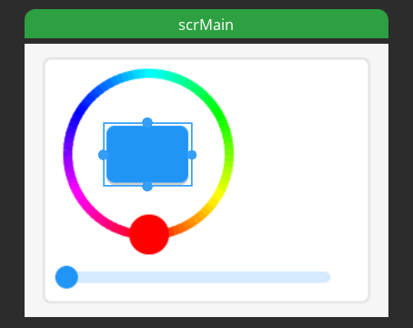
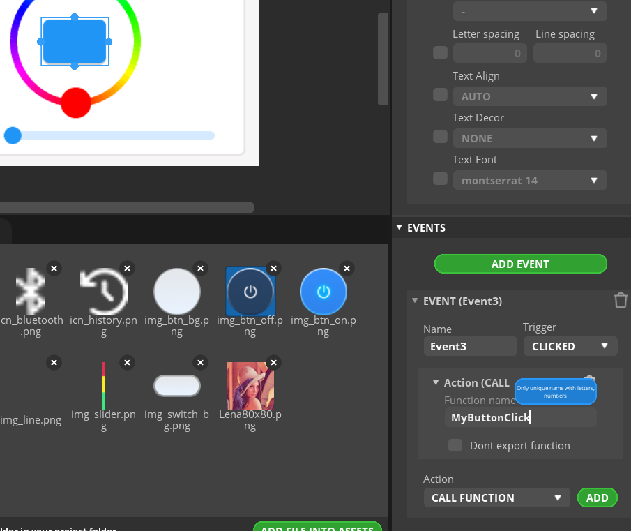
We add objects in SquareLine Studio:
.
.
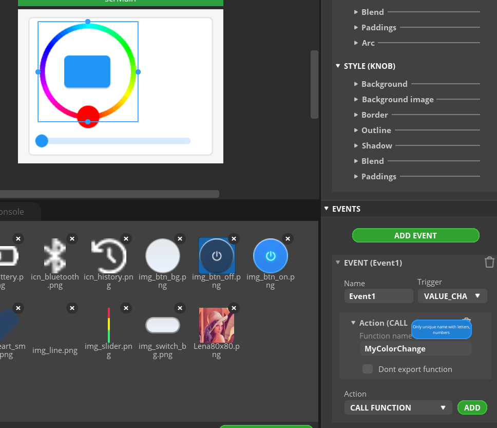
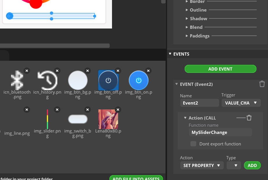
As in the previous section, we also add events:
.
Now it's time to implement the events, i.e. button press, slider move and colour selection separately.
So far without sending data to the lamp.
Button - colour change when pressed (lamp state is either on or off):
Code: C / C++
Log in, to see the code
.
Colour selection - here you need to swap the colour from the packed 16 bit mode to something closer to us, RGB in a more convenient form:
Step 2 - putting everything together .
This step is optional, as with the Tasmota we can send the colour value, brightness level and on/off status separately, but for controlling the LEDs directly from the ESP (e.g. the WS2812 strip) this could still be useful.
So, we have three values (colour, brightness and on/off status) and we want to combine them. The easiest way is to multiply them:
Code: C / C++
Log in, to see the code
.
Of course, this function has to be called after each change.
Step 3 - Tasmota/OpenBeken control interface .
However, let us return to the control of the Tasmota device. We will implement communication based on HTTP, this is probably the simplest option, although MQTT could also be considered in the future. Whatever the method, it's worth reading the Tasmota command documentation:
https://tasmota.github.io/docs/Commands/ Regarding HTTP, it is worth reading the related topic, it is about the interface we are using:
OpenBeken as a mini HTTP host - writing pages in Javascript, Tasmota's REST API etc .
That is, we will send commands in the format:
.
Yes, the same can easily be tested in a web browser.
Rather, you should start by connecting to WiFi:
Code: C / C++
Log in, to see the code
.
Now you need to send the command somehow. This is accomplished by the following code snippet:
Code: C / C++
Log in, to see the code
.
I implement the sending of the command in the thread. Otherwise, I would block the refresh of the user interface while waiting for a response from the device. This could take an extremely long time, especially if the target device was offline.
The code above creates a thread using xTaskCreate:
Now we need to put it to use. Let's start with the on/off. We plug these directly into the button, as our manual colour counting is no longer needed:
Code: C / C++
Log in, to see the code
.
Similarly, the slider:
Code: C / C++
Log in, to see the code
.
And the colour:
Code: C / C++
Log in, to see the code
.
Step 4 - Bilateral status synchronisation .
So far we have only done the sending of data to the lamp. What we lack is communication in the other direction. That is, if we externally change the state of our lamp, the state of the touch interface will not change. Simply put, the ESP will not know that something has changed.
In an ideal world, the lamp itself would be able to send us information about changes, but here we are relying on Tasmota's capabilities, so we will have to query the lamp itself about its state.
In Tasmota, the Status command is used for this.
We send:
.
This will need to be parsed using ArduinoJSON, but we've already done a similar thing in the section on getting weather information from the internet.
What's worse is that we need to think about what to do with this response afterwards.
We shouldn't edit the UI from another thread, at least not while it's being refreshed.
In that case, we need to pick up the response from the thread somehow, but it's not as easy as it might seem. How about using the thread-safe queue from FreeRTOS?
https://www.freertos.org/a00018.html Queues from FreeRTOS, like other mechanisms, take care of thread-safety and allow data to be passed safely between threads. We can't just share resources between threads without safeguards, because it can go to errors that are difficult to reproduce and fix.
We define a queue:
Code: C / C++
Log in, to see the code
.
Create a queue (arguments are maximum number and size of element):
Code: C / C++
Log in, to see the code
.
Now the addition to the queue needs to be done, but a moment. First, I also had to change the GET sending code so that it uses HttpClient. This is because the previous code had a problem with a missing Content-Length in the GET response:
Code: C / C++
Log in, to see the code
.
The code above also includes an add to queue - xQueueSend call. In the argument, I specify a long time to wait for the queue to be available, and still release the created buffer if the add fails. Otherwise we would have a memory leak that would quickly run out of memory....
Receive response - called from loop:
Code: C / C++
Log in, to see the code
.
Time to compile and upload - just to check that the code works and that we get a response in the main thread.
Connecting to WiFi...
Connected to WiFi
[ 6344][I][esp32-hal-adc.c:235] __analogReadMilliVolts(): ADC1: Characterized using eFuse Vref: 1072

HTTP GET Status = 200
Received 139 bytes: {"Dimmer":59,"Fade":"OFF","Speed":1,"LedTable":"ON","Color":"77,37,0,0,0","HSBColor":"29,100,97","Channel":[30,14,0],"CT":500,"POWER":"ON"}
[ 7253][I][main.cpp:266] checkForReplies(): [MainThread] Received response: {"Dimmer":59,"Fade":"OFF","Speed":1,"LedTable":"ON","Color":"77,37,0,0,0","HSBColor":"29,100,97","Channel":[30,14,0],"CT":500,"POWER":"ON"}
.
It works! Now it's time for the next step, which is parsing. We need to load this JSON into the appropriate structures. ArduinoJSON will come in handy:
Code: C / C++
Log in, to see the code
.
Similarly, as in the example with the weather. We deserialise the JSON:
Code: C / C++
Log in, to see the code
.
Then we need to apply a trick. We want to support both reading from the full state, where we need to search for the element StatusSTS , and from the truncated state (where the document root is StatusSTS ). To do this, we first look for StatusSTS, and if we do not find it, we assume that the root itself is this object. Whether we get a full or truncated status from Tasmota in response depends on which command we use.
Code: C / C++
Log in, to see the code
.
Once we have extracted the statusSTS, the brightness level (Dimmer), on/off status (POWER) and colour in HSB format (HSBColor) can be selected from it:
Code: C / C++
Log in, to see the code
.
Then we need to save the received information to our internal variables.
Code: C / C++
Log in, to see the code
.
The biggest fun is with the colour, because we need to convert it to RGB. We have a ready-made function for this from the internet. It is worth mentioning here that this colour is not multiplied by the brightness level, etc:
Code: C / C++
Log in, to see the code
.
Now you still need the helper function SetColorFromBytes, which essentially just sets the colourWheel from the given RGB:
Code: C / C++
Log in, to see the code
.
Similarly, now a helper function that sets the enabled state on the GUI:
Code: C / C++
Log in, to see the code
.
For convenience, I also added a bSend argument to specify whether the state change should be sent to the target device or not. If we are receiving the state from that particular device, there is no reason to send it back to it.
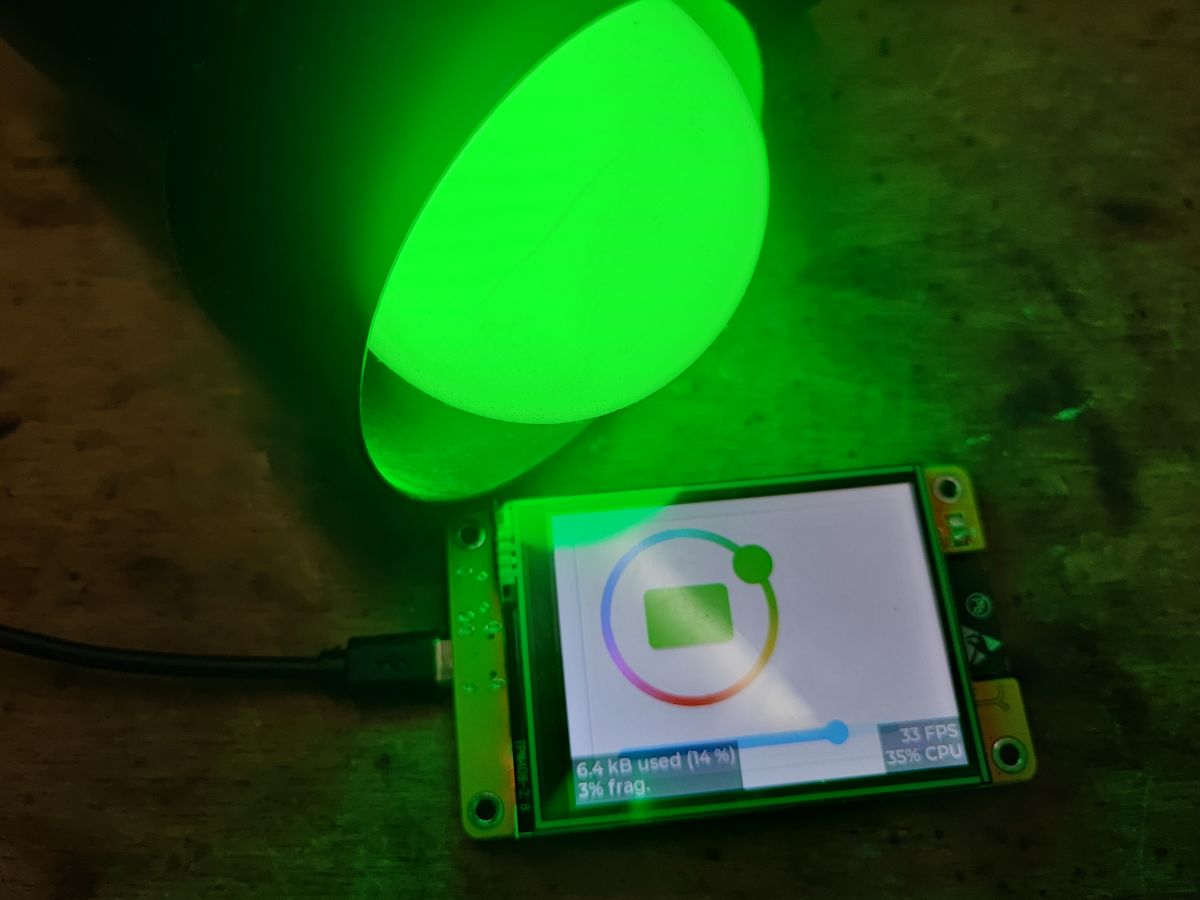
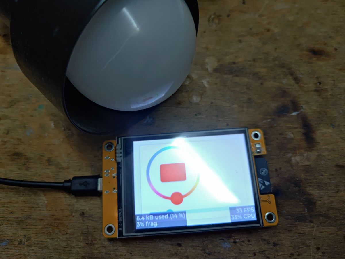
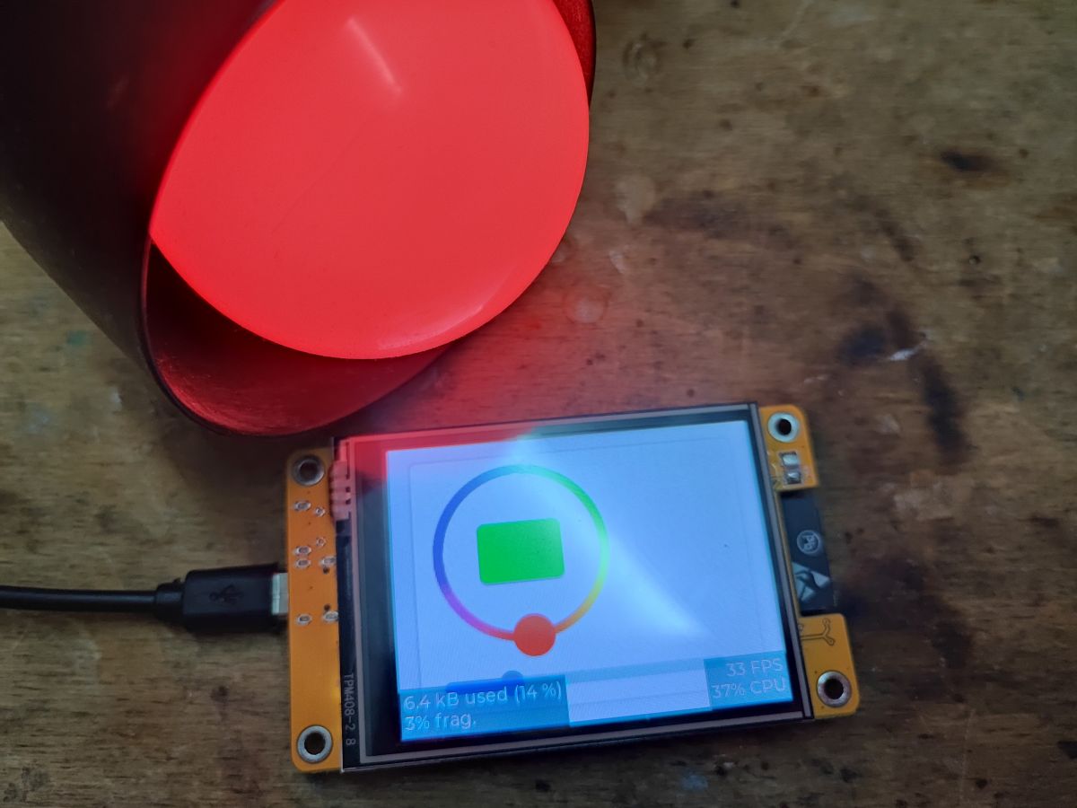
We check, everything works:
.
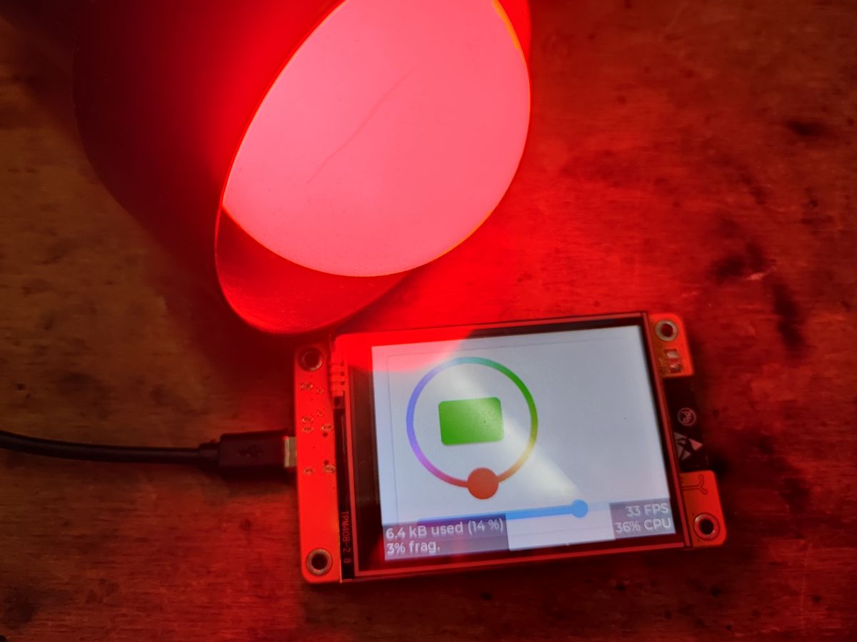
Final test on video:
.
The video shows control of the lamp from its native OBK panel and from the touchscreen display control programme developed here. The communication is two-way, although the states refresh with some small delay. The video shows that, for example, when I move the brightness level bar on the OBK panel, it also moves itself on the touch display.
Summary .
Our program works, the lamp can be controlled, and we got a taste of the basics of linking the user interface to web actions and were again exposed to the JSON format. By the way, we can appreciate LVGL again, because the colour selection widget was for like.
But of course this is not the end of the adventure, now the code could still be significantly improved and optimised. I would consider, for example, abandoning the creation of a new thread separately each time, in favour of a single "worker thread" that would simply perform network operations and collect new "network commands" from some queue. But this was only supposed to be a short demo so this is a secondary issue.
In the next part I will try either to optimise this controller shown here, or I will be tempted to use a slightly different panel, maybe some form of sensor reading? .
About Author
p.kaczmarek2 wrote 14589 posts with
rating 12611 , helped 654 times.
Been with us since 2014 year.
TL;DR: A 4-step ESP32 project uses 3 UI controls and a single HTTP GET pattern to drive a Tasmota or OpenBeken RGB lamp. "It works!" sums up the result: the touchscreen can send Power, Dimmer, and hex Color commands, then sync back lamp state through JSON polling for beginners building a bidirectional wall controller. [#21214560]
Why it matters: This design shows how to turn an inexpensive ESP32 touch panel into a practical RGB lamp controller with two-way status sync instead of one-way button macros.
Option
Transport
Main advantage
Main drawback
HTTP GET to Tasmota/OpenBeken
http://IP/cm?cmnd=...
Simple to test in a browser and easy to implement on ESP32
Needs polling for reverse sync
MQTT
Broker-based messaging
Better candidate for future bidirectional architecture
Not implemented in this project
New FreeRTOS task per command
As used here
Fast to demo and keeps UI responsive
Less efficient than one worker thread
Single worker thread + queue
Proposed improvement
Cleaner architecture for repeated network work
Requires extra queue design
Key insight: Keep LVGL updates on the main thread and move network I/O to FreeRTOS tasks. The queue boundary is what makes two-way HTTP control stable instead of glitchy.
Quick Facts
The UI uses 3 primary controls: an LVGL color wheel, a brightness slider, and an on/off button on the ESP32-2432S028R touch display. [#21214560]
The HTTP control format is a plain GET request such as http://192.168.0.201/cm?cmnd=POWER%20ON, which the author verifies can be tested directly in a browser. [#21214560]
The per-command task is created with a stack size of 8192 bytes and queue capacity is 10 elements of char *, which defines the project’s current response-passing model. [#21214560]
The JSON parser uses StaticJsonDocument<2048> and extracts at least 3 lamp state fields: Dimmer, POWER, and HSBColor for UI synchronization. [#21214560]
The sample status reply reports a lamp at 59% dimmer, POWERON, and an HTTP 200 response with 139 bytes returned, proving round-trip control works. [#21214560]
How do I build a touchscreen RGB lamp controller with an ESP32 and the ESP32-2432S028R display using LVGL?
Build it by creating an LVGL screen with three controls: a color wheel, a brightness slider, and an on/off button. 1. Design the widgets in SquareLine Studio or create them directly in code. 2. Bind each widget to an event handler for color, dimmer, or power. 3. Send each change to the lamp over HTTP and poll status back for sync. The project targets the ESP32 board plus the ESP32-2432S028R touch display and uses LVGL’s built-in color picker widget. [#21214560]
What is Tasmota's HTTP command interface, and how does it work for controlling an RGB lamp over GET requests?
Tasmota’s HTTP command interface is a REST-like endpoint that accepts commands through a URL query string. The project sends GET requests in the form http://IP/cm?cmnd=..., such as POWER ON, Power Off, Dimmer 55, or Color RRGGBB. The target device executes the command and returns JSON, which the ESP32 can parse. The author also notes that this exact request style is simple enough to test in a normal web browser before coding it on the touchscreen controller. [#21214560]
What is OpenBeken, and how does it relate to Tasmota-compatible RGB lamp control?
OpenBeken is firmware that exposes a Tasmota-compatible HTTP control interface, so the same ESP32 commands can control it. "OpenBeken" is device firmware that runs on supported smart hardware, exposes web and automation features, and in this project accepts Tasmota-style /cm?cmnd= requests for RGB lamp control. That compatibility lets the touchscreen controller target either Tasmota devices or OpenBeken lamps without changing the basic command format. The sample lamp status shown in the thread comes from an OpenBeken-based RGBCW E27 device. [#21214560]
How do I send Power, Dimmer, and Color commands from an ESP32 to a Tasmota or OpenBeken device over HTTP?
Send each lamp action as a URL-encoded command string and wrap it in http://IP/cm?cmnd=%s. Power uses Power%20On or Power%20Off. Brightness uses Dimmer%20%i, where the example slider produces values like 54, 55, and 91. Color uses Color%20%02X%02X%02X, which formats RGB bytes as six uppercase hex characters. The thread’s helper builds the URL with snprintf, allocates the string, and dispatches it from a FreeRTOS task so the UI does not stall during the HTTP request. [#21214560]
Why should ESP32 HTTP requests to a Tasmota lamp be sent from a FreeRTOS task instead of directly from the UI event handler?
Send HTTP from a FreeRTOS task because network waits can freeze the LVGL interface. The author states that a direct call inside the UI handler would block screen refresh while waiting for a response, especially if the lamp is offline. The demo therefore creates a task with xTaskCreate(...) and an 8192-byte stack for each command. That keeps button presses, slider movement, and redraws responsive while the request completes in the background. [#21214560]
How do I convert the LVGL color wheel's 16-bit packed color format into standard RGB values on ESP32?
Read the LVGL color, unpack green from 6 bits and red and blue from 5 bits, then scale them upward. The thread does this by combining green_l with green_h << 3, shifting red and blue left by 1, then shifting all three channels left by 2 to approach a 0–255 range. Example log output includes values such as R=248, G=76, B=0 and R=128, G=252, B=0. This gives ESP32-friendly RGB bytes for lamp commands. [#21214560]
What's the best way to format a Tasmota Color command like hex RGB from an LVGL color picker selection?
Format the command as six hex digits after Color%20, using uppercase two-digit bytes for red, green, and blue. The thread uses sprintf(color_command, "Color%%20%02X%02X%02X", red, green, blue);, which turns selected RGB values into a Tasmota-ready command string. That approach is better than sending decimal triples here because it matches the author’s working implementation and keeps the HTTP command compact. It also maps cleanly from LVGL’s color wheel handler to the network send function. [#21214560]
How can I synchronize the ESP32 touchscreen UI with external changes made to the lamp state in Tasmota or OpenBeken?
Poll the lamp’s status and update the UI from the main loop after parsing the JSON reply. 1. Send a Status request to the lamp over HTTP. 2. Push the JSON response from the HTTP task into a FreeRTOS queue. 3. Receive it in the main thread, parse POWER, Dimmer, and HSBColor, then update the button, slider, and color wheel. The thread shows this works both from the native OBK panel and from the ESP32 touchscreen, with a small visible delay during refresh. [#21214560]
How do I parse Tasmota Status or StatusSTS JSON responses with ArduinoJson on ESP32?
Use ArduinoJson to deserialize the payload, then handle both full and short status formats. The code creates StaticJsonDocument<2048>, calls deserializeJson, and first looks for root["StatusSTS"]. If StatusSTS is missing, it treats the root object itself as the status block. After that, it reads fields such as Dimmer, POWER, and HSBColor. This dual-path parser matters because different Tasmota commands can return either the full Status object or a shortened StatusSTS-style payload. [#21214560]
Why does updating LVGL widgets from another thread cause problems, and how do FreeRTOS queues help pass HTTP responses safely?
Updating LVGL from another thread causes race conditions because the UI may be refreshing at the same time. The thread explicitly warns against editing widgets from a worker task and instead uses a FreeRTOS queue as a thread-safe boundary. The HTTP task allocates a response buffer, sends its pointer with xQueueSend, and the main loop pulls it with xQueueReceive. If queue insertion fails, the code frees the buffer to avoid a memory leak. That design makes response handling safer and easier to reproduce during debugging. [#21214560]
How can I update an LVGL slider, color wheel, and on/off button from a parsed Tasmota JSON status reply?
Map each parsed field to one widget and update all three on the main thread. POWER drives the button color through setEnabled, where green means on and red means off. Dimmer updates the slider with lv_slider_set_value(..., LV_ANIM_OFF). HSBColor is converted to RGB, then applied with lv_colorwheel_set_rgb. The sample status block shows values like Dimmer: 11, POWER: OFF, and HSBColor: 2,100,97, which are exactly the fields the UI refresh logic consumes. [#21214560]
Tasmota HTTP vs MQTT for ESP32 lamp control — which approach is better for a touchscreen RGB controller?
HTTP is better for this specific touchscreen demo because it is already implemented, easy to debug, and testable in a browser. MQTT is presented only as a future alternative worth considering. For a first controller, the author chooses HTTP because sending GET commands and parsing JSON replies is simpler than adding broker setup and a second message path. If you want the shortest path to a working RGB touch panel on ESP32, this thread favors HTTP first and leaves MQTT as a later upgrade. [#21214560]
What causes missing Content-Length or HTTP GET response handling issues on ESP32, and why might HTTPClient work better than esp_http_client here?
A missing Content-Length in the GET reply caused problems in the author’s first implementation. He switched from esp_http_client to HTTPClient, then successfully received the payload body and logged HTTP GET Status = 200 with a 139-byte JSON response. That made queue-based response parsing possible. The failure case matters: if you cannot reliably read the body, you cannot sync the slider, color wheel, or power state back to the UI, even when the lamp executes the command correctly. [#21214560]
How do I convert Tasmota HSBColor values into RGB so the LVGL color wheel shows the correct lamp color?
Parse the HSBColor string into three integers, convert HSB to RGB, and feed the result into the LVGL color wheel. The thread uses sscanf(hsbColor, "%d,%d,%d", ...) on values like 224,95,96, calls a helper HSBtoRGB(...), and then updates the widget with SetColorFromBytes(red, green, blue). That helper builds an lv_color_t with LV_COLOR_MAKE and calls lv_colorwheel_set_rgb. This keeps the touchscreen color selector visually aligned with the lamp’s actual external state. [#21214560]
What would be a better architecture for this project: creating a new FreeRTOS task for every command or using one worker thread with a queue?
One worker thread with a queue would be the better long-term architecture. The author says the current design creates a new task for each command only because it is a short demo. A single worker thread would perform all network operations and collect pending commands from a queue, which reduces repeated task creation overhead and centralizes error handling. The current model works, but the proposed worker design is cleaner for frequent slider moves, repeated polling, and future feature growth. [#21214560]

Comments