PIC12F683 and SDCC - whole clock and thermometer on two pins (no external libraries)
 .
.
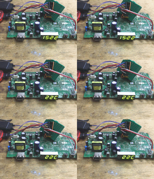
Today I'm going to show the project on a tiny eight-pin PIC microcontroller in a DIP8 case offering a modest 3.5kB of Flash memory. What's more, I will use only two pins to communicate with the peripherals - the whole thing will be based on I2C. Based on these I will run a display/keyboard controller and a thermometer. Finally, I will make a first attempt to enrich the whole thing with a countdown timer so that the circuit built can act as a clock. There will also be an option to set the current time.
This mini-project is somewhat related to my SDCC tutorial for the PIC18F2550 and I will here partly build on the steps described there:
Part 1 - Setting up the operating environment
https://www.elektroda.pl/rtvforum/topic3635522.html#18304424
Part 2 - Blink LED, IO pins, digital inputs and outputs
https://www.elektroda.pl/rtvforum/topic3647884.html#18389188
Part 3 - Oscillator settings. Internal oscillator, external oscillator, quartz resonator, PLL
https://www.elektroda.pl/rtvforum/topic3657704.html
Part 4 - Timers, interrupts
https://www.elektroda.pl/rtvforum/topic3676645.html#18580858
Part 5 - Seven-segment display operation
https://www.elektroda.pl/rtvforum/topic3676650.html#18580877
Part 6 - MM5450 LED display driver
https://www.elektroda.pl/rtvforum/topic3845301.html
The table of contents will be completed as I write more parts.
Related topic about the PIC12F683:
PIC12F683 and SDCC - tutorial - creating a simple dimmer (read datasheet notes) .
I will write the whole thing in SDCC under PIC12F683 without external libraries .
For practical reasons, I will not repeat the knowledge from the previous parts in detail here.
Project plan .
I will start by running the PIC12F683 in internal oscillator mode. Here I will mainly focus on configuring its pins from the oscillator as GPIOs, as I already showed the rest in the previous section. Then I will use these two pins to communicate with the display/keyboard controller. I will first start showing the individual digits and then reading the keys. At this stage I'll have more or less the software functions for I2C ready, so I'll try to use them to additionally connect a simple TC74 thermometer to the same bus and read the results from that too. Finally, I will deal with the more "clock" stuff, i.e. I will implement simple timekeeping based on a hardware timer from the PIC, and finally I will put it all together so that both time and temperature can be displayed, and the current time can be set using buttons.
The project will be continued in the second part.
Parts used .
In summary, to project I will use:
- PIC12F683 in DIP08 enclosure - main microcontroller
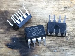 .
.

- display from tuner with controller type TM1650/TM1637/HD2015/itd, also similar modules can be purchased online, their communication protocols are often similar but not identical
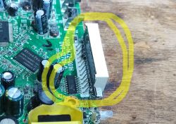
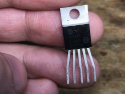
- TC74 (thermometer with simple I2C-based interface)
- PICKIT2 for PIC programming (or any other programmer that can handle it)
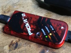 .
.
- optionally, a 5V power supply to power the finished project, in my case from an old tuner
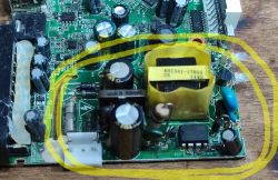 optional.
- optionally, a logic state analyser to see what is happening on the lines from I2C....
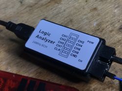 .
.
Step 1: Blink .
To start with, I always run the 'blink' programme which is the simplest LED flashing. This allows me to make sure that the firmware actually starts. I try to avoid situations where, for example, a program is uploaded but not executed, e.g. due to the MCLR (RESET) pin not being connected according to the datasheet. I also make sure then that I upload a firmware compatible with the MCU I have on the table.
So I started according to the previous topic in the series:
PIC12F683 and SDCC - tutorial - we create a simple dimmer (read the datasheet notes) .
Here, however, I have made a minor correction as I noticed that the 'clock' pins do not flash along with the others:
 .
.
You have to search for what is wrong. Type "CLKIN" into the search engine in the catalogue note and browse the results:
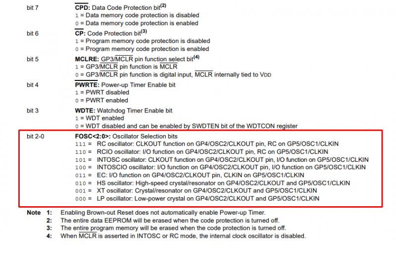 .
.
The Config register (configuration word) defines the role of these pins. We want to set both of them in GPIO mode, so we add the CONFIG register setting to the internal oscillator without CLKOUT:
Code: C / C++
All code:
Code: C / C++
Works:
Step 2: Getting the display .
The display used (or rather the displays, as I first carried out the project on one board and after a break started on a second, similar one) are from an old tuner:
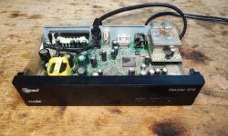
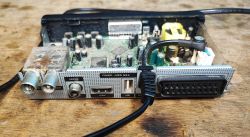 .
.
Inside there is usually the main CPU, Flash memory, RAM, separately the head, and, well, the keyboard/display chip that interests me:
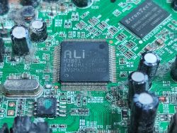
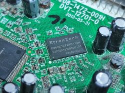
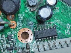
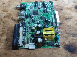 .
.
One advantage of using such equipment is a free power supply with an output voltage of generally 5V, although 3.3V on the board (after the step-down converter) will also be found:
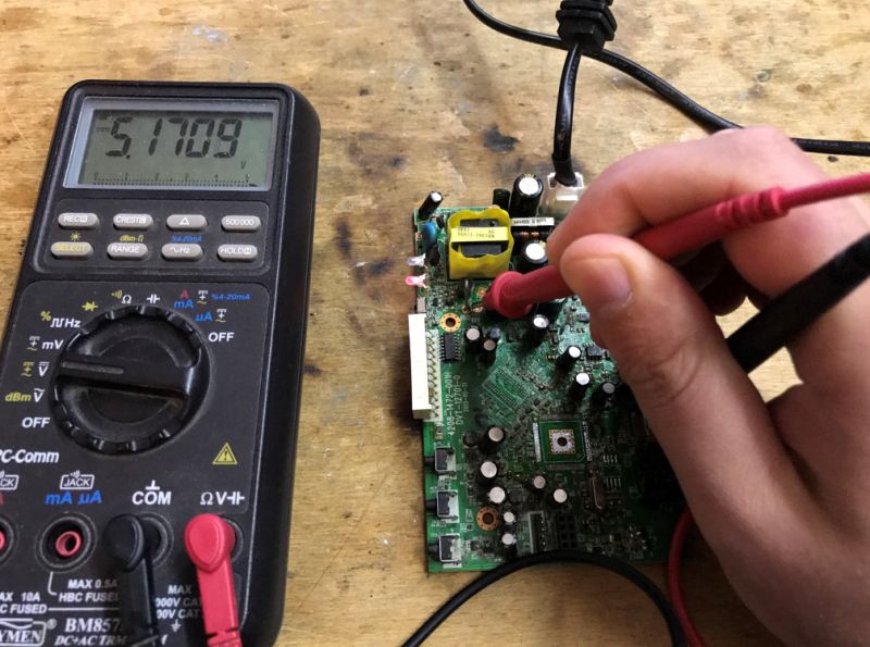
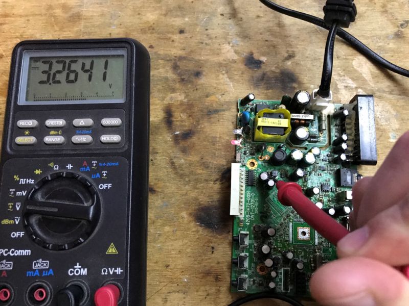 .
.
In this case the power supply is based on the PN8136:
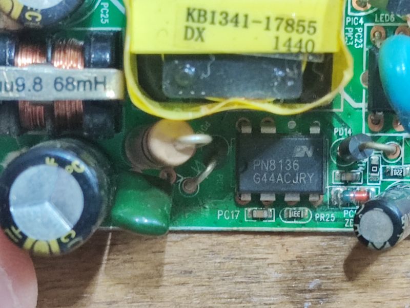 .
.
A second plus is the display often found in such products with control based on an I2C-like protocol (but generally without chip addresses?):
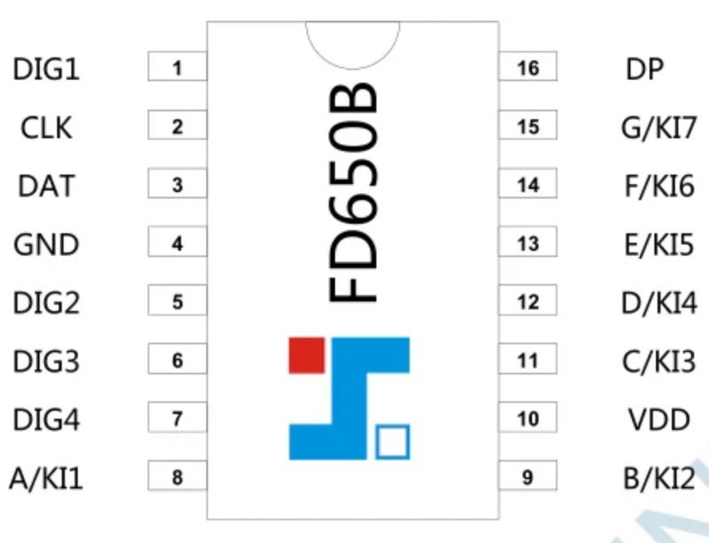
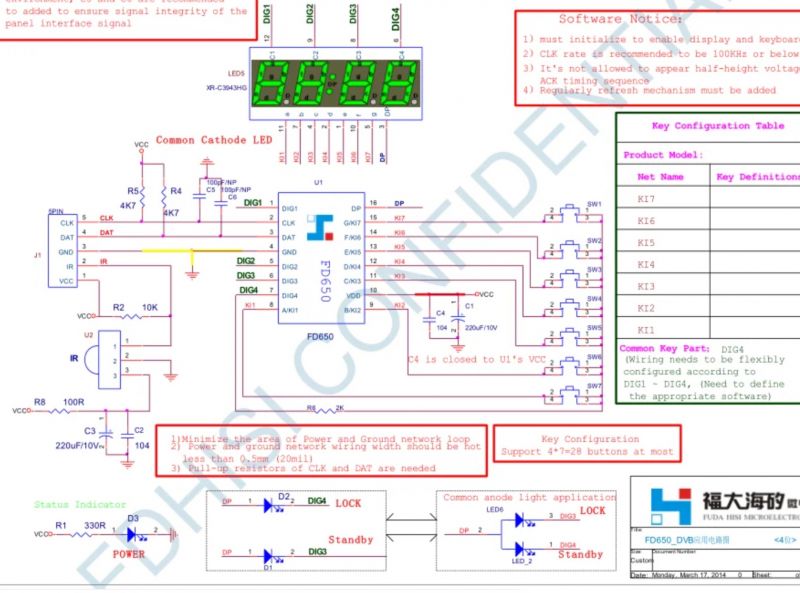 .
.
Communication with the chip here is over two lines only - SDA and SCL, data and clock. Communication is bi-directional, the SDA is capable of both sending data and reading it. So, it's time to connect the SDA and SCL to the two selected legs of the PIC and start the adventure....
However, if you want to buy such a display, interesting modules can be found on the web:
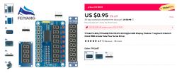 .
.
Step 3: I2C communication .
FD650 has already been run by someone on the forum:
4x7seg LED controller - FD650B + AVR (Bascom) .
The FD650 is not compliant with the I2C standard, as it does not have its own address separately, but instead directly "exposes" registers to the bus. These exposed registers are several, so an I2C scan will see it as several devices. In addition, this means that you won't connect two FD650Bs on one I2C bus, as you can with e.g. the MCP23017 if you set them to different addresses....
By the way, it resembles very strongly the popular TM1650/HD2015/CH455H which I have already discussed. I refer you to the following topics for details :
Running the HD2015 display/button controller after reverse engineering, comparison with TM1637itd .
Read the datasheet note and write the CH455H 7-segment LED display driver in Arduino .
7-segment displays on TM1637 - 4 and 6 digits - Arduino, protocol .
The register addresses match. Based on the above topics, we have:
- 0x48 - configuration register
- 0x68, 0x6A, 0x6C, 0x6E - character registers
So I have rewritten to SDCC my code from the above mentioned topics:
Code: C / C++
It works, the segments of the first digit flash.
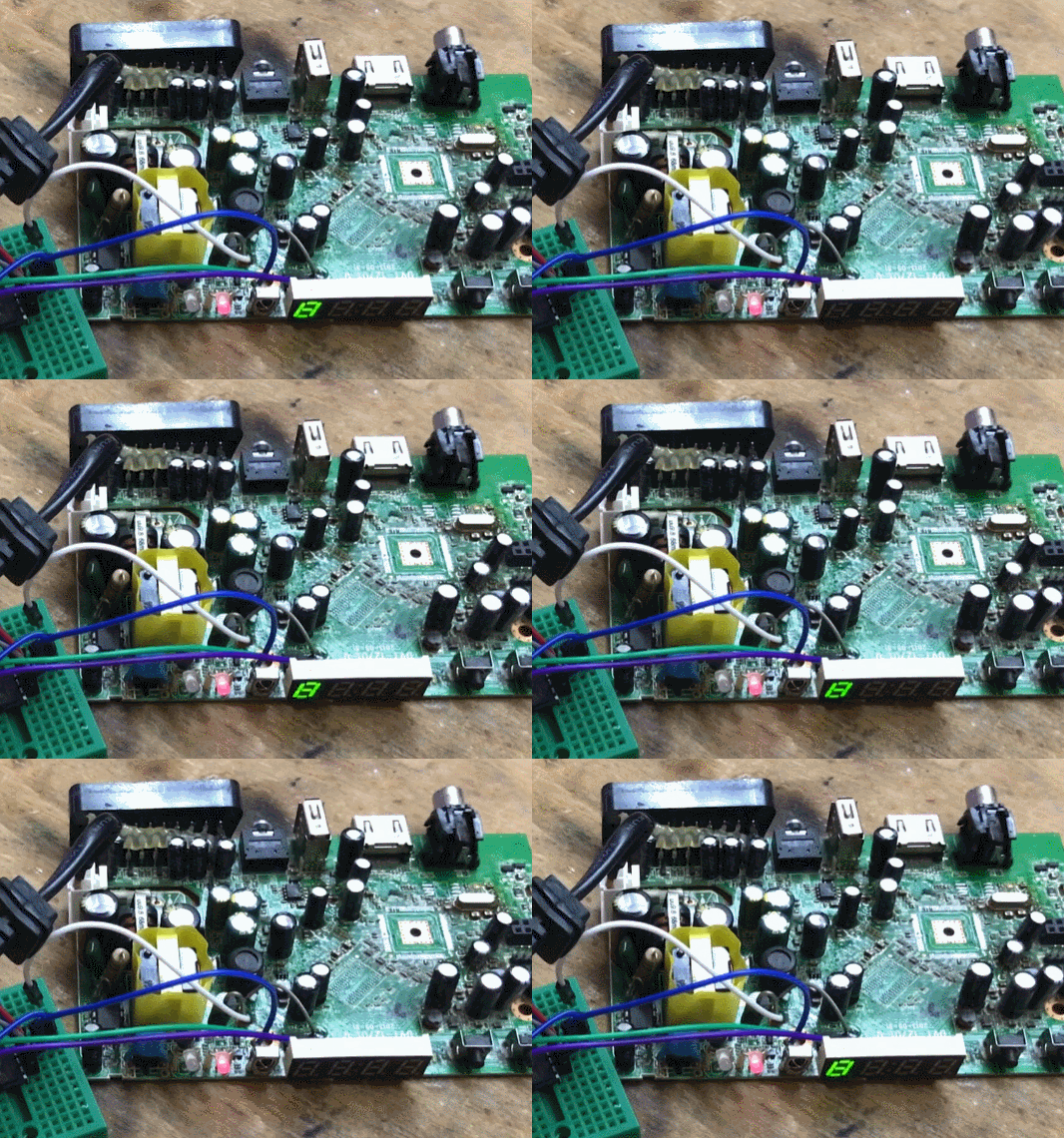 .
.
In order to validate the code I suspected the whole thing on a logic analyser from the subject Salae 24MHz logic state analyser for £40 - analysis of unknown LED display protocol :
 .
.
Step 4: Countdown and characters .
In this case, the character map I developed in a previous topic also fitted. It is also compatible with commercially available TM1650/TM1638 modules, etc:
Code: C / C++
You get to the segments of a given digit (or even more broadly, character, as I have up to F characters) by simply indexing the array with the given value.
To start with, I fired up the simplest "countdown":
Code: C / C++
The result:
Based on this, you can make a function that splits a number into digits using integer and modulo division operations; below is a three-digit version:
Code: C / C++
And here the "watch" version, i.e. two separate numbers from 0 to 99:
Code: C / C++
With the above function I can already display the time in the form HH:MM or MM:SS.
Step 5: I2C scan .
I then decided to try connecting the second devices on my I2C bus. I wasn't sure how the display controller would behave here, which essentially doesn't have its own single call address, but responds immediately to register addresses. Will it respond to the ack every time?
I had the I2C scanner from this topic:
Building a clock on a PIC18F2550, step by step - part 1, BMP280, TC74, 74HCT164, I2C .
I ported it to myself and modified it to display the corresponding addresses:
Code: C / C++
Now it was time for two separate scans:
- the first without TC74 on the bus
- the second with the TC74, so as to know its address
I simply performed the scans and compared the results.
I got addresses 72, 74, 76, 78, 104 and 106 without the TC74, and the TC74 itself contributed an additional address 154. So it is seen, it is time to read it.
Organisational note .
Due to external factors, I had to delay the project a bit and in the end I carried out the second stage of the project on a slightly different board from the tuner. The digit registers have not changed, but the register of e.g. the buttons has. The rest of the code is unchanged. I have already presented the used board in one of the topics:
Read the datasheet note and write the CH455H 7-segment LED display driver in Arduino .
Step 6: Reading from the TC74 .
I got the TC74 reading code from the topic about the clock:
Building a clock on a PIC18F2550, step by step - part 1, BMP280, TC74, 74HCT164, I2C .
The TC74 is very simple to use, the temperature is as an 8-bit, one byte number, read from a register at address 0x00:
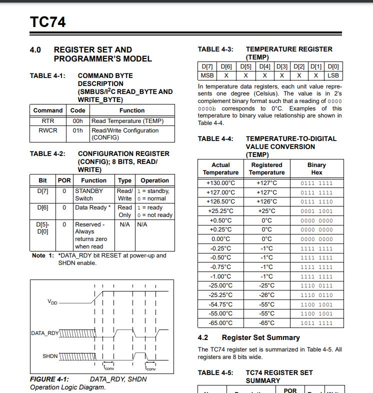 .
.
We first send the register address, here 0x00, preceded by the thermometer address with the W bit (youngest bit turned off) to the thermometer, and then send the byte read, also preceded by the thermometer address, but with the R bit (youngest bit turned on):
Code: C / C++
For simplicity, I did not do a proper I2C "restart" in the code for now, just a separate "stop" and "start".
Result:
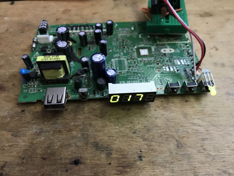 .
.
It works, it's about 17°C in my studio.
Verified with Salae logic state analyser :
 .
.
Step 7: Buttons .
As analysed earlier:
We read the datasheet note and write the CH455H 7-segment LED display driver in Arduino .
The state of the buttons is in a register with address 0x4F, except that it's not simply a bitmap. Anyway, let's check:
Code: C / C++
You can see from the video that there is seemingly something wrong::
The eight-bit word read out turns out to be encoded information about a single button, more precisely its code and separately its pressed state - pressed or released.
Code: C / C++
I uploaded the program and examined the responses to the buttons. There are three on my board, their codes are sequentially 7, 15, 23. Based on this, I have added a button handler which examines what is pressed and, for example, changes one variable:
Code: C / C++
Analogous editing of the current time will be done soon.
As usual, preview the transaction in Pulse View:
 .
.
Step 8: Countdown time .
Countdown time is a little more difficult than it might seem. It would be best to use an external RTCC (Real-Time Clock/Calendar) chip for this, such as the MCP7940N:
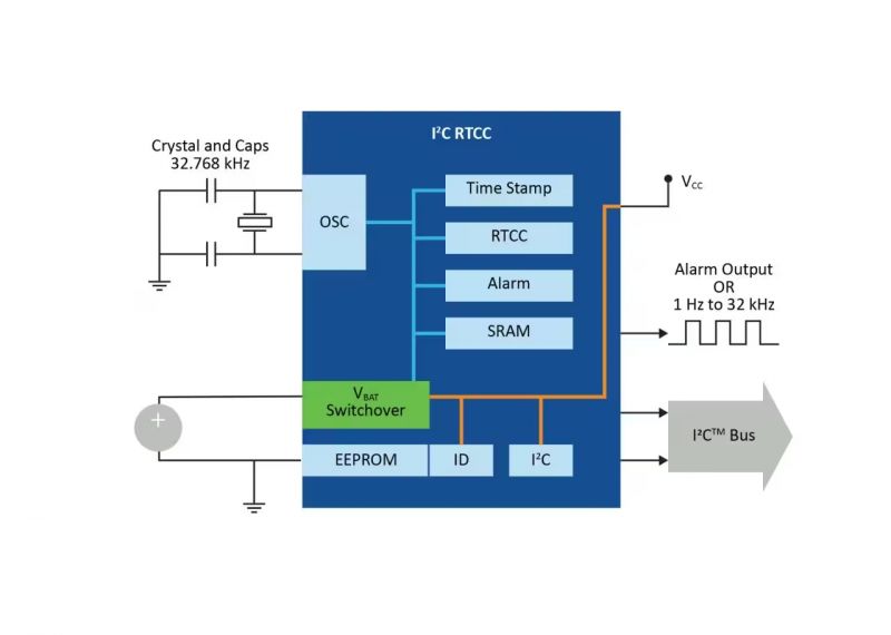 .
.
The advantage of such a solution is that the time is kept even after a loss of power. A small battery or cell is often used for this. Newer PICs also have RTCC built in.
Here, however, in order to simplify things, I will try timekeeping with a timer:
Tutorial PIC18F2550 + SDCC - Part 4 - Timers, interrupts .
Let's take Timer 0 as an example:
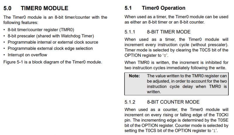 .
.
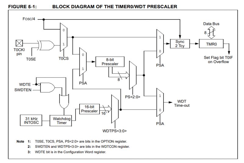 .
.
I set the internal oscillator earlier to 4MHz, so Fosc/4 is 1MHz.
The prescaler can now be selected in OPTION_REG:
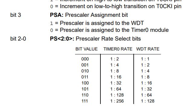 .
.
I chose 1:256, so the timer incrementation will occur not at 1MHz, but at 3.90625 kHz, so the period is 0.256ms.
Now you still need to set from which value the timer will increment:
 .
.
The interrupt is called when the value of TMR0 overflows (exceeds 255, because it's an 8-bit register), so setting TMR0 to 0 will cause the interrupt to call every 256 timer cycles. Since we know that the timer period is 0.256ms, the period of 256 cycles will be 65.53600 ms....
Well, here's a little problem - it's a bit hard to add such counts, it would be much easier to be able to set some better summing period, but for that you would have to change the clock to e.g. the classic 32.768kHz .
32768Hz is not a random value, it is a value of 2 to the power of 15. As if we had Fosc = 32.768kHz, then Fosc/4 would be 8.192kHz. Then by adding a 1:256 prescaler we would get a timer increment every 32Hz, so setting TMR0 to 32 would give us an interrupt every second....
However, I opted for this less precise, inferior solution to begin with and ended up with something like this - timer initialisation and interrupts:
Code: C / C++
Timer interrupt:
Code: C / C++
Here you can see, among other things, why a clock resonator would be better - some time is simply lost here. It would be possible to count in decimal parts of ms, but still far from ideal....
Code: C / C++
In this situation, we count 65.5ms and lose 0.036ms every second on the calculations alone. A day has 86400 seconds, so we lose 3.1104 seconds per day.... 90 seconds in a month.
One could try to make the correction programmatically....
Code: C / C++
However, tests showed that this is not ideal, probably because I did not take into account the inaccuracy of the internal resonator and the instruction execution time.... I experimentally reduced the value of 536 to 200, each time testing the clock separately for a few hours with a stopwatch. Now on a scale of a few hours I am not able to observe latency/speed, for a start it will be enough as I am planning an external RTCC anyway..
You could also transfer this calibration to the EEPROM and just play around for a few days to set it up properly. The contents of the EEPROM are remembered when power is lost, and the PIC used has 256 bytes of it.
Step 8: Time setting .
I implemented the time setting based on the button code shown earlier. I entered a variable to specify the state of the clock (normal operation, hour change, minute change):
Code: C / C++
and then I separately connected the button events:
Code: C / C++
Ultimately you can also loop values here, the hour will be in the range [0,23] and the minutes in the range [0,59].
In addition, in the main loop I do a flashing of the currently edited value (hours or minutes):
Code: C / C++
This lets us know if and what editing mode is enabled.
Step 9: Double-entry .
I have experimentally determined that the colon is plugged into register 0x6C and has a bit code of 32. I have accordingly changed the display code to always light this bit:
Code: C / C++
Step 10: Alternate display of time and temperature .
Finally, I have introduced a simple mechanism for displaying alternating time and temperature. It is based on a "frame"/"refresh" counter, in each loop I check the index of the "frame" and display the selected value based on it. In addition, I check if the edit mode is not active, if so, I always display the time.
Code: C / C++
Effect at the moment .
The clock alternately displays the current time and temperature. The time can be set, although the buttons do not distinguish between when the key is pressed and when the key is held down continuously:
Summary .
Probably the most interesting conclusion from all the fun is that even with these Chinese inventions like TM1650, TM1637 etc., where normal I2C-compatible addressing is missing, it is still possible to give several devices on one bus. I don't mean two TM1650s, of course, as this would be impossible due to the same register addresses, but e.g. TM1650 + TC74 can be made to work.
The clock in its current form works, it works properly on the power supply from the board used, and 5V additionally can also be taken from it.
Of course a lot could still be developed and improved, so in the next part I plan to:
- an attempt to connect and program some RTCC so that the time is counted outside the PIC and additionally is supported by a 3V battery when I disconnect the clock from the mains (or reset the PIC, each upload of a new firmware resets it)
- an attempt to think about and introduce some form of alarm, maybe with a buzzer, also with saving the settings in EEPROM memory, the PIC used has 256 bytes of it
- an attempt to connect some kind of port expander on I2C, if the addresses allow...
- reorganising the code, especially the control and refreshment, to make it more sensible
That's it for now. In the next part we will see how much more Flash memory there is and to what extent I will be able to develop this project further. I am counting on at least these RTCCs... .
I am attaching the "project" (code and batch script for compilation) for reference:


Comments
All nice, but how to get rid of the unnecessary load, i.e. SoC and RAM, from the board of such an STB? This is probably the most difficult step, because you have to precisely solder out the dense chips... [Read more]
As I understand it, you are asking about using hot air for the discharge so that there are no short circuits? I remove short circuits with a braid, in addition I use flux. The braid allows you to effectively... [Read more]
Wau, pretty old skool wrx. Kłaniam się, proszę pana !!! Added after 3 [minutes]: Like I do... If blinking, everything gona be alright ;-) [Read more]