Converts the LED backlight from an Acer S236HL LCD monitor into a WiFi-controlled LED strip using a BK7231 module and OpenBeken.
Uses the board’s 5V rail plus a 3.3V LDO, then drives the EUP2588 backlight controller through EN and PWM signals after cutting the original control paths.
The WiFi module runs on 3.3V, but the strip’s controller accepts a high level from 2.4V, so a 3.3V MCU can drive it directly.
On/off and brightness control worked, and the strip integrated with Home Assistant through OpenBeken.
The freed LED strip still needs a proper heatsink or aluminum rail, because the bare tape-mounted strip will overheat and fail quickly.
AI summary based on the discussion. May contain errors.
.
In a previous topic I showed the inside of an Acer S236HL LCD monitor along with its LED backlight. Here I will convert the remnants of this monitor into a WiFi controlled LED strip. For this I will use a WiFi module with a chip similar to the ESP8266 (BK7231). My chip will allow me to control the brightness of the strip and turn it on and off. By using OpenBeken, the whole thing will also be compatible with Home Assistant, allowing this strip to be controlled from any other supported switch and grouped together with other LED strips.
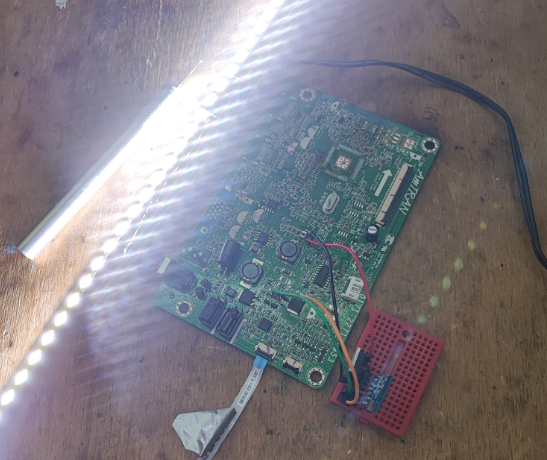
So back to the board:
.
The board connected loosely to the backlight and power supply (no buttons, LVDS, etc) still lights up the backlight.
To start with I checked what the voltages were on the board. I found 3.3V, but had doubts about its current capacity. The WiFi module sometimes needs more than 100mA at 3.3V. In the end I decided to use the 5V line but together with the 3.3V LDO:
.
So the power supply we have.
Now how to control the LEDs?
.
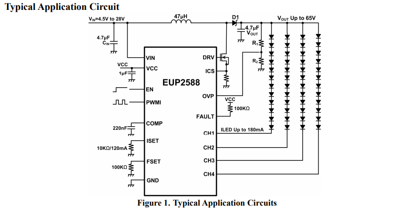
EUP2588:
.
We need the EN (enable) and PWM (brightness control) signals.
EN requires a high state to enable:
.
And PWM:
.
Only question now, how is this connected to the main controller?
Need to see if this can be driven from the MCU:
.
The high level is from 2.4V, so an MCU running at 3.3V will be able to drive this.
I also looked for a schematic. This particular board was not available, but I looked at similar schematics:
.
I was a bit surprised that there is a pull-up here with a transistor, now a high state on the base of this transistor will result in a low state on BKLT_EN.... but this can be corrected in the firmware.
This starts with the power supply:
.
The WiFi module has checked into the network, it works.
Now EN and PWM - I examined the paths and came to the conclusion that, as in the schematic attached above, the main MCU here controls them via transistors. In addition, they do indeed have pull-up resistors.
So I cut the path:
.
On/Off works:
.
LEDs can be controlled.
I have connected the PWM similarly:
.
In the OBK I enabled the PWM (the two buttons are a side effect of the PWM and Enable pins separately):
.
Finally, I gradually soldered the unnecessary components off the PCB:
.
I had concerns that the main processor was controlling something else, that maybe there was a transistor along the way and that I would have to short or switch it, but no. The isolated LED chip continues to work.
.
The video doesn't show the effect very well, as the camera adjusts to the brightness of the strip and you can't see the dimming very well....
What remains is to free the LED strip from the housing. It is glued to it with a special double-sided tape. All you have to do is lever it up with a thin knife:
.
This way you get a freed LED strip:
.
Only now note - the belt in this form is not able to dissipate heat effectively and will damage itself quickly! Now you need to find some way to cool it properly, maybe stick it on some angle iron etc.
In addition, I have added a script in the OBK for improvement purposes:
again:
setChannel 2 $led_enableAll
delay_s 0.1
goto again
.
This script automatically exposes the LED controller state to the second channel.
Summary .
This time there were no major problems. Basically, it turned out that the entire LED module is controlled by just two signals - Enable and PWM - which are easily produced on an external MCU. Additionally, there was already a step-down inverter on board the board providing 5V, so there was no problem with the external power supply only giving 19V.
On the firmware side it also went smoothly, I only had to add a small script to control the EN pin, and to because practically all LED strips on sale do not have an EN pin, and only the PWM alone controls them, and here there is a separate EN and a separate PWM.
Basically the project is successful, now I just need to find a rail for these LEDs (to dissipate heat) and then mount them somewhere. By the way, do you have any suggestions on how to implement this? What to glue them with? Perhaps in the third part, I will show the implementation of this, also with some kind of mounting or housing for the controller (I will add an encoder so that it can also be controlled without WiFi).
About Author
p.kaczmarek2 wrote 14743 posts with
rating 12839 , helped 659 times.
Been with us since 2014 year.
TL;DR: With 2 control lines—"Enable and PWM"—you can turn an Acer S236HL backlight board into a WiFi LED strip using a BK7231, 5V plus a 3.3V LDO, and OpenBeken. This solves dimming and on/off control for DIY users who want Home Assistant compatibility from reclaimed monitor LEDs. [#21369730]
Why it matters: This retrofit reuses an LCD backlight driver that already accepts logic-level control, so you avoid designing a new constant-current LED supply.
Opcja
Zasilanie modułu WiFi
Powód wyboru
Wynik
Natywna linia płyty
3.3V
Autor miał wątpliwości co do wydajności prądowej
Nie wybrano
Linia pomocnicza + stabilizator
5V + 3.3V LDO
Moduł WiFi potrafi potrzebować ponad 100 mA
Wybrano
Key insight: The backlight section works as a mostly independent LED subsystem. Once you isolate the original MCU paths, an external BK7231 can drive EN for on/off and PWM for brightness directly.
Quick Facts
The original external supply provides 19V, while the board already generates 5V, which the author used with a 3.3V LDO for the BK7231 module. [#21369730]
The author rejected the board’s native 3.3V rail because a WiFi module can need more than 100 mA, especially during network activity. [#21369730]
The EUP2588 control input high level starts at about 2.4V, so a 3.3V MCU output is sufficient for EN and PWM drive. [#21369730]
The OpenBeken helper script refreshes channel state in a loop with delay_s 0.1, exposing the LED controller status on a second channel. [#21369730]
After removing the strip from the monitor frame, the author warns that it cannot dissipate heat properly and may fail quickly without a metal mounting rail or similar heatsink. [#21369730]
How do you convert an old Acer S236HL TV or monitor LED backlight into a WiFi-controlled LED strip using a BK7231 module and OpenBeken?
You reuse the monitor’s LED driver board and let a BK7231 control its EN and PWM lines through OpenBeken. 1. Power the WiFi module from the board’s 5V rail through a 3.3V LDO. 2. Trace and isolate the original EN and PWM paths by cutting the PCB traces. 3. Wire the BK7231 outputs to those lines, then configure PWM and Enable in OpenBeken. The result gives on/off control, brightness control, and Home Assistant integration without building a new LED power stage. [#21369730]
What is the EUP2588 and how does it control LED backlight power, enable, and brightness on an LCD monitor board?
"EUP2588 is an LED driver IC that powers an LCD backlight, accepts a separate enable input and a PWM dimming input, and is designed to regulate the backlight section independently from the main monitor controller." On this board, the author identified EN as the on/off control and PWM as the brightness control. That matters because the chip already exposes the two functions needed for external MCU control, so the backlight can run after the original logic is bypassed. [#21369730]
Why was the 5V rail with a 3.3V LDO chosen instead of using the board’s native 3.3V supply for the BK7231 WiFi module?
The 5V rail with a 3.3V LDO was chosen because the board’s native 3.3V line might not supply enough current. The author specifically noted that the WiFi module can need more than 100 mA at 3.3V. Using 5V plus a local LDO gives a safer supply margin during WiFi activity and avoids brownouts that could reset the BK7231. The board already had 5V available, so this was the simplest stable power path. [#21369730]
Which signals on the LED driver board need to be connected to an external MCU to get on/off control and dimming, and how do EN and PWM work here?
You need only two signals: EN for on/off and PWM for brightness. EN must go high to enable the LED driver, while PWM sets the dimming level. The author summarized it clearly: "the entire LED module is controlled by just two signals." That is why a 3.3V MCU can replace the original monitor controller for lighting control, as long as it drives both lines correctly and accounts for any inverted transistor stage on the board. [#21369730]
Why did the author cut PCB traces before wiring the BK7231 to the LED driver, and how do pull-up resistors and transistors affect that mod?
The author cut the PCB traces to isolate the LED driver inputs from the original main controller circuitry. The board used pull-up resistors and transistor stages, so the old MCU could still influence BKLT_EN and PWM if those paths stayed connected. In the similar schematic the author checked, a high level on a transistor base could produce a low level on BKLT_EN, which inverts logic. Cutting the traces prevents signal contention and lets firmware handle any required inversion cleanly. [#21369730]
What is OpenBeken and how does it make a BK7231-based LED strip compatible with Home Assistant?
"OpenBeken is firmware for BK7231-class WiFi modules that exposes GPIO control, PWM functions, and automation features, making custom hardware behave like a networked smart device." In this project, it let the author assign PWM and Enable pins, script channel behavior, and connect the converted backlight to Home Assistant. That means the strip can be switched, dimmed, and grouped with other supported lights from the same automation system. [#21369730]
How do you configure PWM and a separate Enable pin in OpenBeken when the LED driver does not behave like a typical single-PWM LED strip?
You configure two outputs instead of one because this driver separates brightness from power enable. The author enabled PWM in OpenBeken and used a second control path for EN, noting that common LED strips usually use PWM alone, while this board needs distinct PWM and Enable handling. Because the board’s transistor network can invert EN, firmware may need inverted logic for that pin. That two-signal setup is why the interface showed separate controls during testing. [#21369730]
What does the OpenBeken script with setChannel and led_enableAll do, and why is a second channel needed for this LED controller?
The script mirrors the LED enable state onto channel 2 so the controller exposes a usable status signal. It loops continuously with delay_s 0.1 and runs setChannel 2 $led_enableAll, which keeps the second channel synchronized with the actual LED enable condition. The author added it because this board has separate EN and PWM behavior, unlike many strips that use only one PWM-controlled light channel. The extra channel makes the device model fit the hardware better. [#21369730]
How can you tell whether a 3.3V microcontroller output is high enough to drive the EN and PWM inputs of an LED driver like the EUP2588?
You compare the driver’s input-high threshold with the MCU output voltage. Here, the author checked the EUP2588 information and saw that the high level begins at about 2.4V. A 3.3V microcontroller output is therefore high enough to assert both EN and PWM inputs. That verification matters before wiring any external controller, because if VIH were higher than 3.3V, the LED driver might switch unreliably or fail to dim correctly. [#21369730]
What problems can happen if you remove the LED strip from the original monitor housing and run it without proper heatsinking?
The strip can overheat and damage itself quickly without proper heatsinking. The author explicitly warned that once removed from the original housing, the strip no longer dissipates heat effectively. In practice, the monitor chassis acted as part of the thermal path, so free-air use is unsafe for sustained operation. You need a metal support, such as an angle profile or rail, before long-term use at normal brightness. [#21369730]
What is the best way to mount and cool a reclaimed LCD backlight strip after removing it from the panel, and what adhesive or thermal tape should be used?
The thread’s practical recommendation is to mount the strip onto a metal rail or angle section so it can shed heat. The author suggested something like angle iron after warning that the bare strip will fail quickly without cooling. The post does not specify a brand or type of adhesive, so the safe takeaway is mechanical mounting to a heat-spreading metal support rather than leaving the strip attached only by its original tape. [#21369730]
BK7231 vs ESP8266 for a WiFi LED strip retrofit — which is better for OpenBeken, PWM dimming, and Home Assistant integration?
In this project, BK7231 was the better choice because the build actually used it with OpenBeken and achieved PWM dimming plus Home Assistant support. The author described the chip as similar to an ESP8266, but did not test ESP8266 here or compare performance figures. The verified result is that a BK7231-based module joined WiFi, controlled EN and PWM, and worked with OpenBeken on this Acer backlight conversion. [#21369730]
How do you safely free an LED backlight strip that is glued in with double-sided tape without damaging the LEDs or the diffuser parts?
You lift it carefully with a thin knife rather than tearing it away. 1. Start at an edge where the tape bond is easiest to access. 2. Gently lever the strip upward a little at a time. 3. Keep separating the adhesive gradually so the strip does not bend sharply. The author states that the strip is fixed with special double-sided tape and can be freed this way. The main risk is mechanical damage if you pry too aggressively. [#21369730]
What troubleshooting steps help when the backlight turns on but dimming does not work after connecting a WiFi module to the EN and PWM lines?
First verify that PWM is connected to the correct trace and enabled in OpenBeken. Next confirm that the EN and PWM paths are isolated from the original MCU, because leftover transistor or pull-up networks can override your signal. Then check logic polarity, especially if the board inverts BKLT_EN through a transistor stage. The author got on/off working first, then added PWM separately, which is a strong troubleshooting sequence when brightness control fails but the backlight still powers up. [#21369730]
What components from an old TV or monitor LED power board can be removed after the mod, and how do you verify the remaining LED driver still works standalone?
You can remove unnecessary sections after confirming the isolated LED driver still powers and controls the strip correctly. The author gradually desoldered unneeded PCB components only after WiFi power, EN control, and PWM dimming were already working. He also checked that the LED section kept functioning after separation from the main processor path, proving the remaining driver was effectively standalone. Remove parts in stages, not all at once, so any failure can be traced to the last change. [#21369730]
AI summary based on the discussion. May contain errors.


Comments