Generator - wobulator on Arduino UNO/NANO + AD9833 possibly ESP32 Wemos D1
Edit: 03-10-2025:
I have corrected the circuit diagram for normalising the output signals, and refined the buffer (emitter secondary) which was causing some problems.
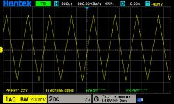
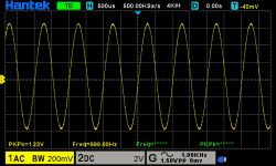
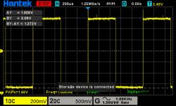
Just for fun, I committed a function generator, sine, triangle and rectangle based on the AD9833 programmable generator (SPI).
 .
.
 .
.
 .
.
The project uses a choice of Arduino UNO/ NANO or ESP32 in Wemos D1 R32 (or suitable clones) as the generator controller.
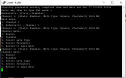
In addition, the CPU of course implements the operator interface, in this case the simplest possible in the form of a serial port character console.
It is possible to select the type of signal, frequency, enable or disable a given channel (maximum 2).
 .
.
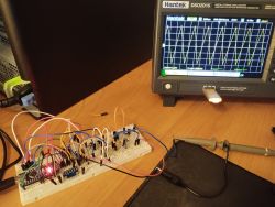
For now, I only have it in prototype form plugged into a contact board:
 .
.
Additionally, I used the ESP32 DAC output or an external DAC (MCP4725, i2C) plugged into the UNO/NANO to generate a "ramp signal" to control the second channel of the oscilloscope. So that the oscilloscope moves the amplitude of the generator output while the programmable generator changes the frequency of the sine wave on the first input, in a preset range with a preset step. This creates a sort of primitive wobulator:
.
The problem with the AD9833 circuit is the difference in amplitude of the generated signal, for the sine and triangle it is 600mV p-p, and for the rectangle it is practically rail to rail.
I wondered how to solve this elegantly to have the same amplitude regardless of the type of signal chosen. My first idea was to use an electronic potentiometer controlled from the procec (X9C103S). It varied the attenuation of the signal (equalised downwards) depending on the selected waveform type.
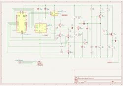
In the end, I chose a slightly more complex solution involving the design of an analogue circuit that creates two signal paths.
On one of these paths is an amplifier with a common emitter (for sine and triangle). On the other path, a resistor (mounting potenciometer) suppresses the rectangle before entering the signal mixer. Then there is already an output emitter secondary. In general the circuit may be so-so, my experience in electronics is to have read the electronics course from EP .
.
 .
.
Obviously, inserting this number of transistors in the output worsened the parameters of the maximum frequency achieved by the generator.
The power supply to the analogue part is drawn directly from the CPU board, which is certainly not the most optimal solution.
That is, we power the generator from the same PC on the USB port with which we chat via the character console.
I would welcome suggestions on how to improve.
In the current edition of the schematic with the corrected secondary, the output signal is set to be a nice 1V p-p.
You can find the software at this link: https://github.com/bucefal76/signal_generator_ad9833
Ready to compile under VSC with PlatformIO (ESP supported on Arduino framework not native ESP32).
The exact generator configuration is there, see README.md, further Include/ModuleConfig.hpp.
I will warn you in advance that it may be a bit too complex at first glance for an amateur Arduino sketcher.
If one feels like rummaging around inside, it is worth reading about MVC to start with: https://pl.wikipedia.org/wiki/Model-View-Controller
I have corrected the circuit diagram for normalising the output signals, and refined the buffer (emitter secondary) which was causing some problems.
Just for fun, I committed a function generator, sine, triangle and rectangle based on the AD9833 programmable generator (SPI).
 .
.
 .
.
 .
.
The project uses a choice of Arduino UNO/ NANO or ESP32 in Wemos D1 R32 (or suitable clones) as the generator controller.
In addition, the CPU of course implements the operator interface, in this case the simplest possible in the form of a serial port character console.
It is possible to select the type of signal, frequency, enable or disable a given channel (maximum 2).
 .
.
For now, I only have it in prototype form plugged into a contact board:
 .
.
Additionally, I used the ESP32 DAC output or an external DAC (MCP4725, i2C) plugged into the UNO/NANO to generate a "ramp signal" to control the second channel of the oscilloscope. So that the oscilloscope moves the amplitude of the generator output while the programmable generator changes the frequency of the sine wave on the first input, in a preset range with a preset step. This creates a sort of primitive wobulator:
The problem with the AD9833 circuit is the difference in amplitude of the generated signal, for the sine and triangle it is 600mV p-p, and for the rectangle it is practically rail to rail.
I wondered how to solve this elegantly to have the same amplitude regardless of the type of signal chosen. My first idea was to use an electronic potentiometer controlled from the procec (X9C103S). It varied the attenuation of the signal (equalised downwards) depending on the selected waveform type.
In the end, I chose a slightly more complex solution involving the design of an analogue circuit that creates two signal paths.
On one of these paths is an amplifier with a common emitter (for sine and triangle). On the other path, a resistor (mounting potenciometer) suppresses the rectangle before entering the signal mixer. Then there is already an output emitter secondary. In general the circuit may be so-so, my experience in electronics is to have read the electronics course from EP
 .
.
Obviously, inserting this number of transistors in the output worsened the parameters of the maximum frequency achieved by the generator.
The power supply to the analogue part is drawn directly from the CPU board, which is certainly not the most optimal solution.
That is, we power the generator from the same PC on the USB port with which we chat via the character console.
I would welcome suggestions on how to improve.
In the current edition of the schematic with the corrected secondary, the output signal is set to be a nice 1V p-p.
You can find the software at this link: https://github.com/bucefal76/signal_generator_ad9833
Ready to compile under VSC with PlatformIO (ESP supported on Arduino framework not native ESP32).
The exact generator configuration is there, see README.md, further Include/ModuleConfig.hpp.
I will warn you in advance that it may be a bit too complex at first glance for an amateur Arduino sketcher.
If one feels like rummaging around inside, it is worth reading about MVC to start with: https://pl.wikipedia.org/wiki/Model-View-Controller


Comments
Cool project. Especially when it comes to wobuloscopic measurements, which somehow have lost their popularity these days. It's a shame, because they carry a lot of information. But in truth, here in today's... [Read more]
The ADC in the ESP32 is a misunderstanding. Would have to add an external converter. [Read more]
AVE... In a podcast about DDS generators from a few years ago I mentioned a minor flaw in the modules with AD9833, well the output filter is wrong in them. It might be worth bypassing it and seeing... [Read more]
Thanks for sharing the project, quite a few things on ESP32 are implemented :) . I couldn't find a frequency range or precision anywhere? Send a packet and I'll send a small gift. [Read more]