[WIP] Della Mini Split TCWBRCU1 Wi-Fi Module Disassembly and Flashing Guide with OpenBeken
TL;DR
- Teardown and flashing guide for the TCWBRCU1 Wi-Fi/Bluetooth module inside a Della Optima Series 9,000 BTU mini split, model 048-TP-9K2V-23S-IN.
- It traces the indoor-unit dongle, exposes the WBR3 module, identifies passthrough holes and UART pins, then shows desoldering and OpenBeken flashing via AmebaZ2 Download Tool.
- The system runs on 115V, 60Hz, carries a SEER2 rating of 23, and the flashing path targets RTL87X0C firmware with a 3.3 V UART setup.
- OpenBeken installation enables local Wi-Fi control and Home Assistant MQTT integration, but removing the RF shield damaged the WBR3 pads and a replacement module was hard to source.
Generated by the language model.
Disclaimer:
Welcome to this guide, which is a work in progress and may be updated or revised as new information becomes available. While the instructions aim to make the teardown and modification process straightforward and safe, I am not responsible for any damage to your equipment or injury to yourself or others. Disassembling or modifying the unit may void warranties and could cause unforeseen issues if not done carefully.
Please proceed with caution. Electrical components can be hazardous. Always disconnect power completely before beginning any work and use appropriate safety equipment. Follow safety guidelines closely and if unsure, consult a professional. Use this guide at your own risk.
---
Introduction & Overview
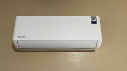
This teardown covers the smart control module found inside a Della Optima Series mini split air conditioner, model 048-TP-9K2V-23S. This is a 9,000 BTU wall-mounted ductless unit capable of both cooling and heating. It features built-in Wi-Fi control and Bluetooth capabilities, making it a target of interest for integration with open-source smart home platforms such as OpenBeken or Tasmota.
The specific module under review is the TCWBRCU1, which hosts a soldered WBR3 Wi-Fi module based on the Realtek RTL8710BN chipset (RTL87X0C family). This chipset is increasingly common in smart appliances and has growing community support for firmware replacement and reverse engineering.
The mini split system is manufactured by Align, Inc. and sold under the Della brand, commonly available through online marketplaces like Amazon. This teardown focuses primarily on the indoor unit (048-TP-9K2V-23S-IN), where the control board and Wi-Fi module are located.
The goal of this teardown is to document the internal hardware, identify communication interfaces, and evaluate the potential for third-party firmware support or local control integration.
Unit Identification
The Della Optima Series Mini Split is a high-efficiency, wall-mounted ductless HVAC system designed for both residential and light commercial applications. It offers versatile climate control with smart connectivity features.
Manufacturer: Align, Inc. (sold under the Della brand)
Indoor Unit Model: 048-TP-9K2V-23S-IN
Outdoor Unit Model: 048-TP-9K2V-23S-OUT
SEER2 Rating: 23
Cooling Capacity: 9,000 BTU
Heating Capacity: 9,000 BTU
Power Supply: 115V, 60Hz
Features: Wi-Fi control, Bluetooth capabilities, Energy Star rated, Inverter technology
Installation Type: Wall-mounted (Indoor), Outdoor unit with condenser coil
Current Equivalent Model (as of May 12, 2025): Link
The system operates on a 115V power supply and is designed to provide effective cooling and heating in spaces up to 400 square feet. The unit features Energy Star certification, ensuring energy-efficient operation and potential cost savings on energy bills.
The Main Control Board of the system is the TCWBRCU1, which interfaces with the indoor and outdoor units, controlling temperature regulation, fan speed, and other essential functions. The control board also communicates with the WBR3 module, which provides Wi-Fi connectivity for remote access and integration with smart home platforms.
The WBR3 module is based on the Realtek RTL8710BN chipset, a member of the RTL87X0C family, which is commonly used in IoT devices for its low power consumption and robust wireless capabilities. This module is key to enabling the Wi-Fi and Bluetooth features of the mini split, allowing for remote control and automation integration.
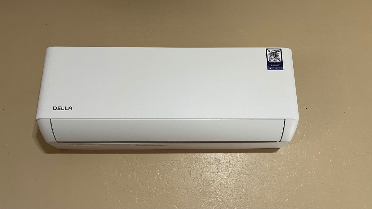
Images of 048-TP-9K2V-23S-IN
(Click to enlarge)
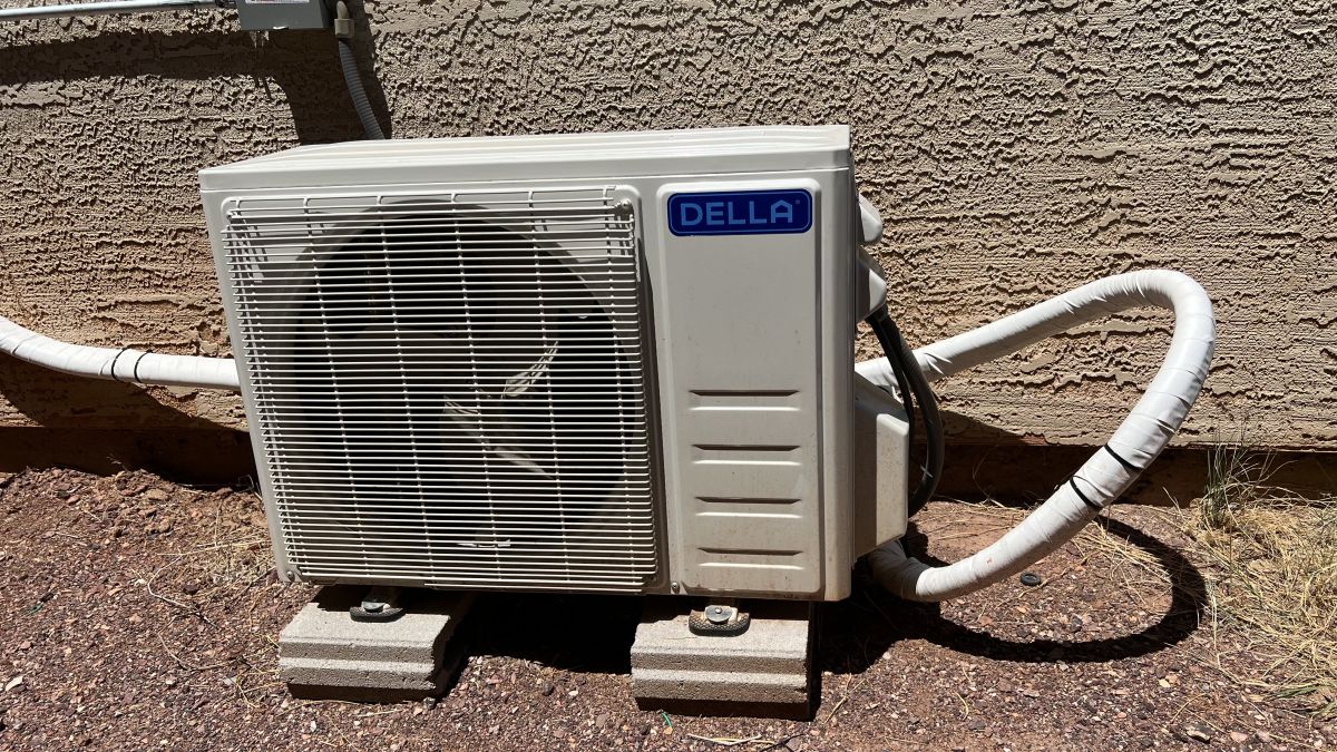
Images of 048-TP-9K2V-23S-OUT

(Click to enlarge)
Tools & Safety
For this teardown, it's assumed that your Della Optima Series Mini Split is already installed and in working order. Below are the tools I used during the process. Each item listed is linked to the specific product I used for this teardown.
Tools Used:
Safety Considerations:
Since the unit is already installed and functioning, it's important to:
•Ensure Power is Off: Before starting any work, always double-check that the power to the unit is fully disconnected. A multimeter is highly recommended to confirm there is no live voltage.
•Handle Components Carefully: Take care not to damage any electrical components or wiring during the teardown process.
•Use Proper Ventilation: If you're using a heat gun or working with soldering equipment, ensure the area is well-ventilated.
Module Details – WBR3
The WBR3 module is the Wi-Fi and Bluetooth communication module used in the Della Optima Series Mini Split. This module provides the functionality for remote control via Wi-Fi and Bluetooth, allowing the mini split to be integrated with mobile apps and smart home platforms.
Key Features:
•Wi-Fi and Bluetooth Connectivity: The WBR3 enables wireless control and communication with the mini split system, allowing for remote operation through a mobile app or smart home system.
•Chipset: The module is powered by the Realtek RTL8710BN chipset, a low-power, dual-mode Wi-Fi and Bluetooth solution designed for efficient wireless communication.
•Energy Efficient: The WBR3 is designed for low power consumption, ensuring reliable wireless performance without significantly draining power.
Physical Description:
The WBR3 is a small, compact module mounted onto the mini split’s main control board. It is typically connected to the control board via a ribbon cable or a set of pins.
Disassembly Notes & Chip Identification:
While it’s not necessary to remove the RF shield to identify the components in the WBR3 module, I did so during my teardown for further inspection. However, please note that I had already lifted too many solder pads on the chip, rendering it unusable for future flashing. If you're attempting this yourself, I recommend skipping the RF shield removal to avoid unnecessary risks.
If you do choose to remove it, use a heat gun and fine-tipped pliers, or tweezers, with care. Even heat application will help prevent damage to nearby components.
After removing the shield, the following chip markings were visible:
• Chipset marking: W701 N9C91P3 GN37A2 — consistent with the Beken BK7231N SoC
• Flash marking: Not identified in this teardown. However, many WBR3 modules commonly include an 8Mb SPI NOR flash such as the XTX XT25F08B, though exact part numbers may vary by batch.
Functionality:
•Remote Control: With Wi-Fi and Bluetooth capabilities, the module enables remote management of the mini split, providing users with the ability to control temperature settings, fan speeds, and more.
•Smart Home Integration: The module supports integration with popular smart home platforms, allowing for automation and control based on environmental conditions or other triggers.
Flashing Information:
The WBR3 module can be flashed with OpenBeken firmware for advanced customization, allowing you to adjust settings, gain additional control, and integrate the unit more seamlessly with third-party smart home devices.
Replacement and Datasheet:
If you need a replacement WBR3 module, the only reliable source I found was AliExpress, as most major electronics suppliers don’t carry it. Alternatively, you could try contacting Della support directly to inquire about a replacement. You might also find compatible modules in other mini split units or similar appliances, but availability is hit-or-miss.
Purchase Link (AliExpress): Link
Datasheet: Link
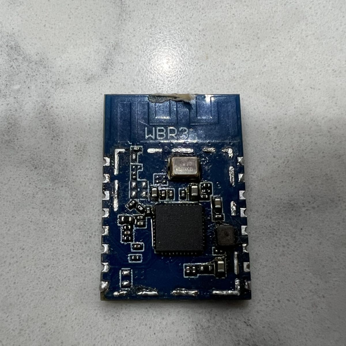
Images of WBR3 Module
Damaged WBR3 with the shield removed.

(Click to enlarge)
Module Details – TCWBRCU1
The TCWBRCU1 is the Wi-Fi/Bluetooth module found in the mini-split system, responsible for enabling wireless communication for remote control and smart home integration. Below are the key details and specifications of the TCWBRCU1 module:
General Information:
• Module Name: TCWBRCU1
• Functionality: The TCWBRCU1 provides the communication interface between the mini-split system and user devices via Wi-Fi and Bluetooth. It allows for remote operation of the system, including controlling temperature, fan speed, and other settings.
• Connectivity:
-Supports both Wi-Fi and Bluetooth protocols
-Enables integration with smart home ecosystems for automation and voice control
Module Components and Pinout:
The TCWBRCU1 module is integrated into the mini-split system with various key components. The module connects to the control board and provides a bridge for wireless communication. Below are the main components and pins of the TCWBRCU1:
• Wi-Fi/Bluetooth Chips:
The TCWBRCU1 uses chips such as the RTL8710BN (for Wi-Fi) to handle wireless communication. This chip allows the module to interface with wireless networks and Bluetooth devices.
• Pins for External Connections:
The module has pins for power (VCC), ground (GND), and communication (RXD, TXD, EN, etc.) that can be accessed for various use cases, including firmware flashing and further customization.
• Passthrough Holes:
The TCWBRCU1 is designed with passthrough holes that allow for probing or connecting wires without needing to desolder the module. This feature is useful for testing or when you want to interface with the module without physically modifying it.
Connectivity Options:
• Wi-Fi: The module supports Wi-Fi communication, allowing users to connect their mini-split systems to home networks for remote control and integration with other smart devices.
• Bluetooth: Bluetooth connectivity allows direct pairing with smartphones or other devices for easy control without relying on Wi-Fi.
Solder Pads & Pinout Overview:
The TCWBRCU1 has a series of solder pads for power and communication connections, including:
• VCC – Power supply input
• GND – Ground connection
• RXD – Serial data reception (RX)
• TXD – Serial data transmission (TX)
• EN – Enable pin for module functionality
• GPIO Pins – General-purpose I/O pins, including A_0, A_15, and A_16, useful for analog inputs.
Physical Design:
• Form Factor: The TCWBRCU1 is a small, compact module designed to fit easily within the mini-split system, typically mounted on or near the main control board (TCWBRCU1).
• Mounting: The module is generally mounted using either a soldered connection or via a female USB-A connector, depending on the specific unit configuration.
• Accessibility: The module is designed for easy accessibility for maintenance, replacement, or upgrades.
Datasheet:
Datasheet: Link
Replacement Information:
At the time of writing, I was unable to find a source for purchasing a replacement TCWBRCU1 module directly. If you need a replacement, your best option is to contact Della Support for further assistance.
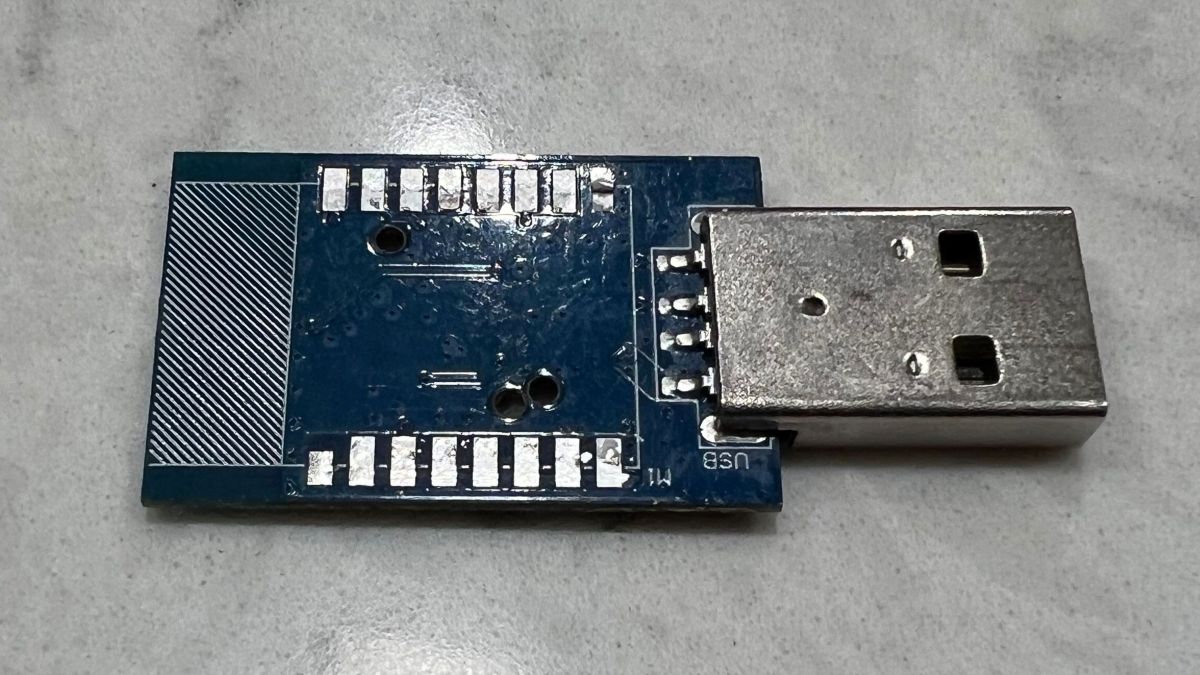
TCWBRCU1_V1.0.0 Images
Top view of the left WBR3 pins while still soldered to TCWBRCU1.

(Click to enlarge)
Top view of the right WNR3 pins while still soldered to the TCWBRCU1.

(Click to enlarge)
Bottom view of the TCWBRCU1 while WBR3 is still soldered.

(Click to enlarge)
Closer image of the bottom view. I am fairly certain these are pass through holes to the WBR3 flashing pins. According to the datasheet, these should be pins A_0, A_1 and A_15.

(Click to enlarge)
View of the TCWBRCU1 with the WBR3 removed.
(Click to enlarge)
Physical Disassembly
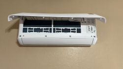
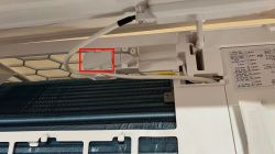
• Open the Front Cover: Start by opening the front cover of the indoor unit to expose the evaporator coil. The evaporator coil is the part with metal fins that helps with heat exchange.

(Click to enlarge)
(Click to enlarge)
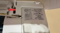
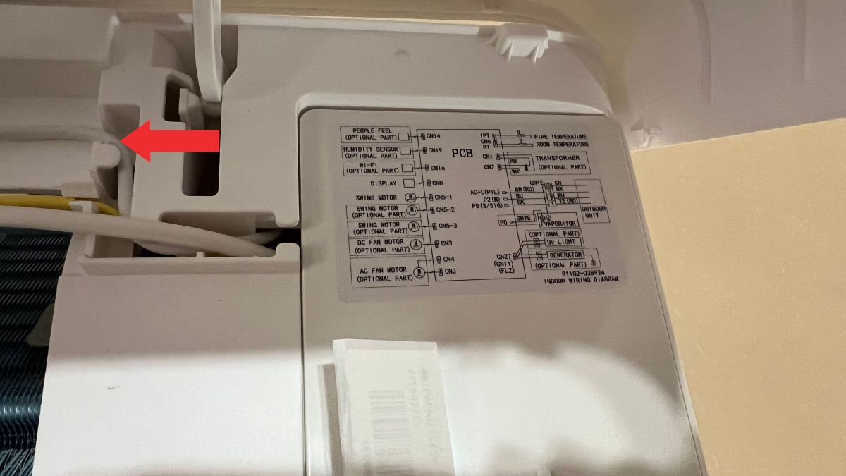
• Locate the Cable: Above the evaporator coil, you will notice a cable running from behind an access panel. Follow this cable to the left.
(Click to enlarge)
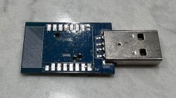
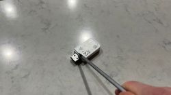
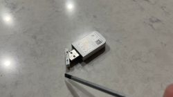
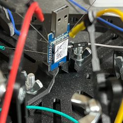
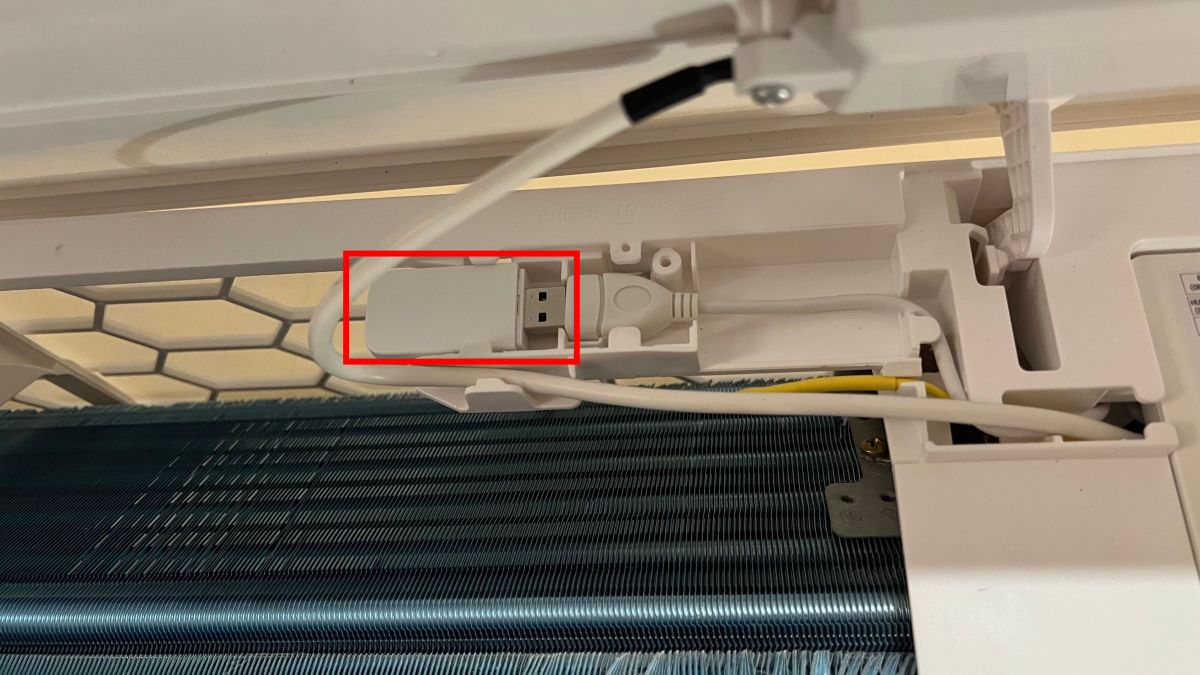
• Identify the TCWBRCU1 Module: The cable leads to a female USB-A connector with a dongle attached. This dongle houses the TCWBRCU1 Wi-Fi/Bluetooth module.
(Click to enlarge)
• Remove the Module: Carefully pull the module out of the cable.

(Click to enlarge)
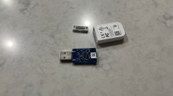
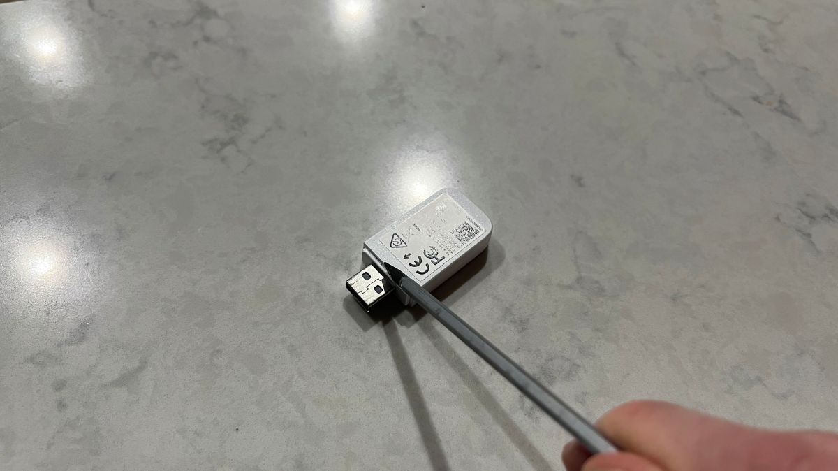
• Open the Dongle Housing: Use a small spudger, pry tool, or small slotted/flat-head screwdriver to gently pry open the dongle’s plastic housing.
(Click to enlarge)
(Click to enlarge)
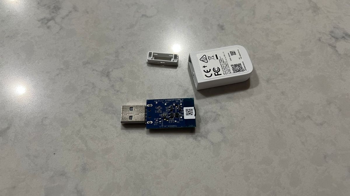
• Slide the Module Out: Once the housing is open, the TCWBRCU1 module should slide out easily.
(Click to enlarge)
Desoldering the WBR3 from the TCWBRCU1 Module
In this section, we’ll cover how to desolder the WBR3 module from the TCWBRCU1 Wi-Fi/Bluetooth module. There are several methods to achieve this, each with its advantages. The method that worked best for me was the heat gun method, but I’ll outline a few options for you to consider.
Desoldering Methods:
• Method 1: Heat Gun (Preferred):
The heat gun method was the fastest, cleanest, and easiest for me. It involves applying consistent, controlled heat to the solder joints, melting them all at once, and then lifting the WBR3 module.
- Apply flux to the solder joints of the WBR3 pins to ensure better heat distribution.
- Use a heat gun with a concentrated nozzle. Set it to low heat, and keep the concentrator tip moving in a circular motion to evenly heat all the solder joints.
- Once the solder is molten, use a pair of fine-tipped tweezers to gently lift the WBR3 from the PCB.
- Let the module cool down before continuing to the next step.
• Method 2: Soldering Iron with Desoldering Solder:
If you prefer to use a soldering iron, this method involves desoldering solder, which makes the process more effective for removing the solder.
- Heat up your soldering iron and add a small amount of desoldering solder to the joints of the WBR3 pins.
- Wait for the desoldering solder to melt, and then use a solder pump or solder wick to remove the excess solder.
- Repeat until all the solder is removed from the pins.
- Once the pins are free, gently lift the WBR3 using tweezers.
• Method 3: Soldering Iron and Solder Wick:
This method is similar to the previous one but uses only solder wick to absorb the molten solder. It’s effective, but it might take longer than the other methods.
- Heat the soldering iron and place a small piece of solder wick on the solder joints.
- Press the heated soldering iron onto the wick, allowing the solder to flow into the wick.
- Once all the solder is removed, carefully lift the WBR3 module.
Prepping the WBR3 for Use
After successfully desoldering the WBR3 from the TCWBRCU1 module, we can begin the preparation steps for connecting the module to a breadboard, power supply, and UART adapter.
Alternative to Soldering: Using a Probe Setup (optional):
If you’d prefer not to solder the wires to the WBR3 module, there is an alternative approach using a probe setup. The TCWBRCU1 module has passthrough holes, so you can use a setup like the one linked below to probe the pads without desoldering the WBR3:
• 3D-Printed Nano Probes:
I attempted to use a 3D-printed probe setup like the one from this link, which allows for non-invasive probing of the WBR3’s pins. However, I ran into an issue because I was using the incorrect software, which led me to desolder the module before I figured out the mistake.
If you want to go this route, you can try this 3D-printed probe setup, and it may work well for your needs if you’re not comfortable with soldering.
• Remix for Vertical Clamping:
Additionally, I remixed one of the creator’s clamps to hold the TCWBRCU1 vertically, making both the top and bottom of the module accessible. This remix can be found HERE. This modification might be useful if you decide to use probes, as it provides easy access to all the necessary pins.
(Click to enlarge)
Solder the Necessary Wires:
To work with the WBR3, you’ll need to solder Dupont wires to the following pads:
*A_15 (LOG_RXD) is located on the underside of the WBR3 module.
Use fine soldering wire and a soldering iron to attach Dupont wires to the correct pads on the WBR3 module. Be careful not to apply too much heat, as you could damage the module.

(Click to enlarge)
Connect to a Breadboard
Once the necessary wires are soldered, carefully place the WBR3 module onto a breadboard. Ensure that the module is securely seated and that all connections are stable.
Power Supply and UART Adapter:
Once the necessary wires are soldered to the WBR3, connect the module to the power supply and UART adapter via Dupont cables as follows:
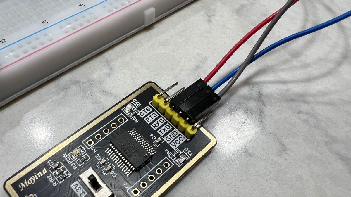
Connection Setup Examples
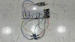
Note: The images below show the correct wiring connections. Your setup should look similar to these photos. In these images, the brown Dupont cable that is not connected is used for shorting the EN pin to GND during flashing to enter bootloader mode.
Overview of All Connections
(Click to enlarge)
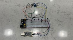
Same Setup from Another Angle
(Click to enlarge)
Close-up of UART Connections
(Click to enlarge)
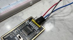
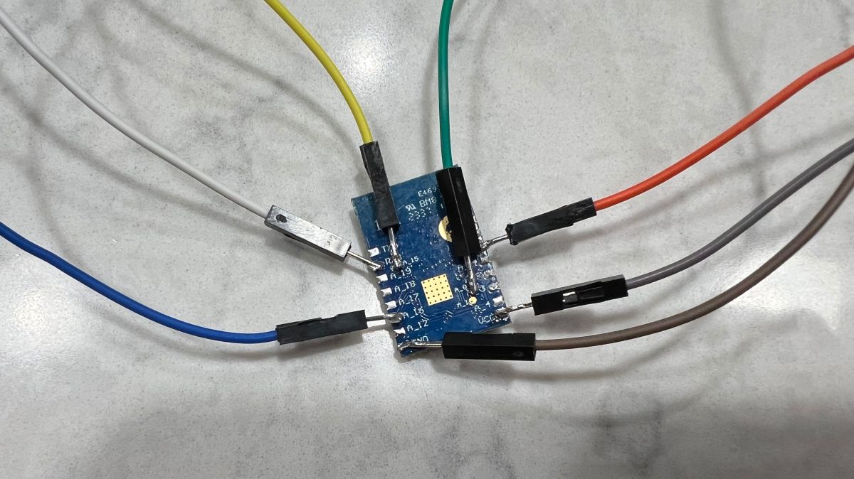
Close-up of WBR3 Connections
(Click to enlarge)
Flashing the WBR3 with OpenBeken (Firmware Installation) (Images coming soon)
Requirements:
• USB-to-UART adapter (3.3 V logic level)
• Stable 3.3 V power source (for example, an AMS1117 regulator)
• Soldering tools or a probe jig to access UART and boot pins
• OpenBeken firmware .bin file for RTL87X0C
• AmebaZ2 Download Tool (PG Tool v1.2.47 or later)
• A basic understanding of the WBR3 pinout (see the “Prepping the WBR3 for Use” section above)
Download the Firmware:
You can find the latest OpenBeken firmware for the WBR3 on GitHub: OpenBeken GitHub Releases
• Scroll to the Assets section under the latest release
• Download the correct firmware file for RTL87X0C
○ OpenRTL87X0C_x.xx.xx.bin is used for flashing via UART
○ OpenRTL87X0C_x.xx.xx_ota.img is used only for OTA updates after OpenBeken is installed
Only the .bin file is needed during the initial flashing process. Save this file to your computer so it can be loaded into the PG Tool.
Flashing Instructions:
• Wire your USB-to-UART adapter to the WBR3 as described in the “Prepping the WBR3 for Use” section. Do not apply voltage to the RXD and A_0 pins yet
• Launch the PG Tool (version 1.2.47 or newer), select the correct COM port, and make sure the target chip is set to RTL87X0C
• When the tool prompts you to enter bootloader mode, apply 3.3 V to both RXD and A_0. Then briefly short the EN pin to GND. The tool should recognize the WBR3 and establish communication
• Use the tool to create and save backups of the original firmware. Make sure to back up both the full flash (approximately 2 MB) and the ROM (approximately 384 KB). Store these backups in a safe location
• Load the OpenBeken .bin file you downloaded earlier into the tool. Select the erase option if prompted, then click Write to begin the flashing process. Wait until the flashing completes successfully
• Remove 3.3 V from RXD and A_0. Then briefly short the EN pin to GND again to reboot the module. The WBR3 should now start running OpenBeken
OpenBeken Wi-Fi Setup and Configuration (Images coming soon)
After flashing and rebooting the WBR3, complete the setup by following these steps:
• On your computer or phone, connect to a new Wi-Fi network named OpenRTL87X0C_XXXXXX
• Open a web browser and go to http://192.168.4.1. This opens the OpenBeken configuration interface
• Scroll to the WiFi Setup section
• Enter the name (SSID) and password of your home Wi-Fi network
• Optionally enter your MQTT settings if you plan to integrate the device with Home Assistant or another platform
• Click Save and then click Reboot
After the reboot, the WBR3 will disconnect from the temporary access point and attempt to join your home Wi-Fi network.
Integration with Home Automation Platforms
This section explains how to integrate the WBR3 module running OpenBeken into your Home Assistant setup using MQTT. It focuses on configuring MQTT, enabling entity auto-discovery, and connecting OpenBeken datapoints to Home Assistant entities for control and monitoring.
Topics may include:
• Setting up MQTT in OpenBeken
• Enabling Home Assistant MQTT discovery
Troubleshooting and Tips
This section highlights real-world issues encountered during the flashing and setup process, along with solutions and useful tips that made things easier.
Topics may include:
• Helpful OpenBeken console commands for testing and debugging
• Fixing UART connection or communication failures
Welcome to this guide, which is a work in progress and may be updated or revised as new information becomes available. While the instructions aim to make the teardown and modification process straightforward and safe, I am not responsible for any damage to your equipment or injury to yourself or others. Disassembling or modifying the unit may void warranties and could cause unforeseen issues if not done carefully.
Please proceed with caution. Electrical components can be hazardous. Always disconnect power completely before beginning any work and use appropriate safety equipment. Follow safety guidelines closely and if unsure, consult a professional. Use this guide at your own risk.
---
Introduction & Overview
This teardown covers the smart control module found inside a Della Optima Series mini split air conditioner, model 048-TP-9K2V-23S. This is a 9,000 BTU wall-mounted ductless unit capable of both cooling and heating. It features built-in Wi-Fi control and Bluetooth capabilities, making it a target of interest for integration with open-source smart home platforms such as OpenBeken or Tasmota.
The specific module under review is the TCWBRCU1, which hosts a soldered WBR3 Wi-Fi module based on the Realtek RTL8710BN chipset (RTL87X0C family). This chipset is increasingly common in smart appliances and has growing community support for firmware replacement and reverse engineering.
The mini split system is manufactured by Align, Inc. and sold under the Della brand, commonly available through online marketplaces like Amazon. This teardown focuses primarily on the indoor unit (048-TP-9K2V-23S-IN), where the control board and Wi-Fi module are located.
The goal of this teardown is to document the internal hardware, identify communication interfaces, and evaluate the potential for third-party firmware support or local control integration.
Unit Identification
The Della Optima Series Mini Split is a high-efficiency, wall-mounted ductless HVAC system designed for both residential and light commercial applications. It offers versatile climate control with smart connectivity features.
Manufacturer: Align, Inc. (sold under the Della brand)
Indoor Unit Model: 048-TP-9K2V-23S-IN
Outdoor Unit Model: 048-TP-9K2V-23S-OUT
SEER2 Rating: 23
Cooling Capacity: 9,000 BTU
Heating Capacity: 9,000 BTU
Power Supply: 115V, 60Hz
Features: Wi-Fi control, Bluetooth capabilities, Energy Star rated, Inverter technology
Installation Type: Wall-mounted (Indoor), Outdoor unit with condenser coil
Current Equivalent Model (as of May 12, 2025): Link
The system operates on a 115V power supply and is designed to provide effective cooling and heating in spaces up to 400 square feet. The unit features Energy Star certification, ensuring energy-efficient operation and potential cost savings on energy bills.
The Main Control Board of the system is the TCWBRCU1, which interfaces with the indoor and outdoor units, controlling temperature regulation, fan speed, and other essential functions. The control board also communicates with the WBR3 module, which provides Wi-Fi connectivity for remote access and integration with smart home platforms.
The WBR3 module is based on the Realtek RTL8710BN chipset, a member of the RTL87X0C family, which is commonly used in IoT devices for its low power consumption and robust wireless capabilities. This module is key to enabling the Wi-Fi and Bluetooth features of the mini split, allowing for remote control and automation integration.
Images of 048-TP-9K2V-23S-IN

(Click to enlarge)
Images of 048-TP-9K2V-23S-OUT
(Click to enlarge)
Tools & Safety
For this teardown, it's assumed that your Della Optima Series Mini Split is already installed and in working order. Below are the tools I used during the process. Each item listed is linked to the specific product I used for this teardown.
Tools Used:
| Tool | Description | Purpose | Link | Breadboard Kit | Includes breadboard, power module, and Dupont cables | Prototyping and connecting components | Link | Power Module | 3.3 V / 5 V power supply (Included in Breadboard Kit) | Provides stable voltage to components | Included | Dupont Cables | Wires for connections (Included in Breadboard Kit) | Connects components without soldering | Included | Soldering Iron | 60 Watt soldering station | Solder wires and components | Link | Solder for Desoldering | Rosin core solder | Remove soldered connections | Link | Solder for Soldering | Rosin core solder | Make soldered connections | Link | Heat Gun | Standard heat gun tool | Heat shrink tubing and reflow solder | Link | Heat Gun Concentrator Nozzle | Nozzle for focused heat | Direct heat precisely | Link | Flux Kit | Includes flux and solder wick | Improve solder flow and remove excess solder | Link | Solder Wick | Included in Flux Kit | Remove solder from joints | Included | Multimeter | Digital multimeter for measuring voltage, current, and resistance | Test electrical connections and troubleshoot | Link | USB UART Cable | USB to UART adapter cable | Serial communication with WBR3 module | Link |
Safety Considerations:
Since the unit is already installed and functioning, it's important to:
•Ensure Power is Off: Before starting any work, always double-check that the power to the unit is fully disconnected. A multimeter is highly recommended to confirm there is no live voltage.
•Handle Components Carefully: Take care not to damage any electrical components or wiring during the teardown process.
•Use Proper Ventilation: If you're using a heat gun or working with soldering equipment, ensure the area is well-ventilated.
Module Details – WBR3
The WBR3 module is the Wi-Fi and Bluetooth communication module used in the Della Optima Series Mini Split. This module provides the functionality for remote control via Wi-Fi and Bluetooth, allowing the mini split to be integrated with mobile apps and smart home platforms.
Key Features:
•Wi-Fi and Bluetooth Connectivity: The WBR3 enables wireless control and communication with the mini split system, allowing for remote operation through a mobile app or smart home system.
•Chipset: The module is powered by the Realtek RTL8710BN chipset, a low-power, dual-mode Wi-Fi and Bluetooth solution designed for efficient wireless communication.
•Energy Efficient: The WBR3 is designed for low power consumption, ensuring reliable wireless performance without significantly draining power.
Physical Description:
The WBR3 is a small, compact module mounted onto the mini split’s main control board. It is typically connected to the control board via a ribbon cable or a set of pins.
Disassembly Notes & Chip Identification:
While it’s not necessary to remove the RF shield to identify the components in the WBR3 module, I did so during my teardown for further inspection. However, please note that I had already lifted too many solder pads on the chip, rendering it unusable for future flashing. If you're attempting this yourself, I recommend skipping the RF shield removal to avoid unnecessary risks.
If you do choose to remove it, use a heat gun and fine-tipped pliers, or tweezers, with care. Even heat application will help prevent damage to nearby components.
After removing the shield, the following chip markings were visible:
• Chipset marking: W701 N9C91P3 GN37A2 — consistent with the Beken BK7231N SoC
• Flash marking: Not identified in this teardown. However, many WBR3 modules commonly include an 8Mb SPI NOR flash such as the XTX XT25F08B, though exact part numbers may vary by batch.
Functionality:
•Remote Control: With Wi-Fi and Bluetooth capabilities, the module enables remote management of the mini split, providing users with the ability to control temperature settings, fan speeds, and more.
•Smart Home Integration: The module supports integration with popular smart home platforms, allowing for automation and control based on environmental conditions or other triggers.
Flashing Information:
The WBR3 module can be flashed with OpenBeken firmware for advanced customization, allowing you to adjust settings, gain additional control, and integrate the unit more seamlessly with third-party smart home devices.
Replacement and Datasheet:
If you need a replacement WBR3 module, the only reliable source I found was AliExpress, as most major electronics suppliers don’t carry it. Alternatively, you could try contacting Della support directly to inquire about a replacement. You might also find compatible modules in other mini split units or similar appliances, but availability is hit-or-miss.
Purchase Link (AliExpress): Link
Datasheet: Link
Images of WBR3 Module
Damaged WBR3 with the shield removed.
(Click to enlarge)
Module Details – TCWBRCU1
The TCWBRCU1 is the Wi-Fi/Bluetooth module found in the mini-split system, responsible for enabling wireless communication for remote control and smart home integration. Below are the key details and specifications of the TCWBRCU1 module:
General Information:
• Module Name: TCWBRCU1
• Functionality: The TCWBRCU1 provides the communication interface between the mini-split system and user devices via Wi-Fi and Bluetooth. It allows for remote operation of the system, including controlling temperature, fan speed, and other settings.
• Connectivity:
-Supports both Wi-Fi and Bluetooth protocols
-Enables integration with smart home ecosystems for automation and voice control
Module Components and Pinout:
The TCWBRCU1 module is integrated into the mini-split system with various key components. The module connects to the control board and provides a bridge for wireless communication. Below are the main components and pins of the TCWBRCU1:
• Wi-Fi/Bluetooth Chips:
The TCWBRCU1 uses chips such as the RTL8710BN (for Wi-Fi) to handle wireless communication. This chip allows the module to interface with wireless networks and Bluetooth devices.
• Pins for External Connections:
The module has pins for power (VCC), ground (GND), and communication (RXD, TXD, EN, etc.) that can be accessed for various use cases, including firmware flashing and further customization.
• Passthrough Holes:
The TCWBRCU1 is designed with passthrough holes that allow for probing or connecting wires without needing to desolder the module. This feature is useful for testing or when you want to interface with the module without physically modifying it.
Connectivity Options:
• Wi-Fi: The module supports Wi-Fi communication, allowing users to connect their mini-split systems to home networks for remote control and integration with other smart devices.
• Bluetooth: Bluetooth connectivity allows direct pairing with smartphones or other devices for easy control without relying on Wi-Fi.
Solder Pads & Pinout Overview:
The TCWBRCU1 has a series of solder pads for power and communication connections, including:
• VCC – Power supply input
• GND – Ground connection
• RXD – Serial data reception (RX)
• TXD – Serial data transmission (TX)
• EN – Enable pin for module functionality
• GPIO Pins – General-purpose I/O pins, including A_0, A_15, and A_16, useful for analog inputs.
Physical Design:
• Form Factor: The TCWBRCU1 is a small, compact module designed to fit easily within the mini-split system, typically mounted on or near the main control board (TCWBRCU1).
• Mounting: The module is generally mounted using either a soldered connection or via a female USB-A connector, depending on the specific unit configuration.
• Accessibility: The module is designed for easy accessibility for maintenance, replacement, or upgrades.
Datasheet:
Datasheet: Link
Replacement Information:
At the time of writing, I was unable to find a source for purchasing a replacement TCWBRCU1 module directly. If you need a replacement, your best option is to contact Della Support for further assistance.
TCWBRCU1_V1.0.0 Images
Top view of the left WBR3 pins while still soldered to TCWBRCU1.

(Click to enlarge)
Top view of the right WNR3 pins while still soldered to the TCWBRCU1.

(Click to enlarge)
Bottom view of the TCWBRCU1 while WBR3 is still soldered.

(Click to enlarge)
Closer image of the bottom view. I am fairly certain these are pass through holes to the WBR3 flashing pins. According to the datasheet, these should be pins A_0, A_1 and A_15.

(Click to enlarge)
View of the TCWBRCU1 with the WBR3 removed.
(Click to enlarge)
Physical Disassembly
• Open the Front Cover: Start by opening the front cover of the indoor unit to expose the evaporator coil. The evaporator coil is the part with metal fins that helps with heat exchange.
(Click to enlarge)

(Click to enlarge)
• Locate the Cable: Above the evaporator coil, you will notice a cable running from behind an access panel. Follow this cable to the left.
(Click to enlarge)
• Identify the TCWBRCU1 Module: The cable leads to a female USB-A connector with a dongle attached. This dongle houses the TCWBRCU1 Wi-Fi/Bluetooth module.

(Click to enlarge)
• Remove the Module: Carefully pull the module out of the cable.
(Click to enlarge)
• Open the Dongle Housing: Use a small spudger, pry tool, or small slotted/flat-head screwdriver to gently pry open the dongle’s plastic housing.
(Click to enlarge)

(Click to enlarge)
• Slide the Module Out: Once the housing is open, the TCWBRCU1 module should slide out easily.
(Click to enlarge)
Desoldering the WBR3 from the TCWBRCU1 Module
In this section, we’ll cover how to desolder the WBR3 module from the TCWBRCU1 Wi-Fi/Bluetooth module. There are several methods to achieve this, each with its advantages. The method that worked best for me was the heat gun method, but I’ll outline a few options for you to consider.
Desoldering Methods:
• Method 1: Heat Gun (Preferred):
The heat gun method was the fastest, cleanest, and easiest for me. It involves applying consistent, controlled heat to the solder joints, melting them all at once, and then lifting the WBR3 module.
- Apply flux to the solder joints of the WBR3 pins to ensure better heat distribution.
- Use a heat gun with a concentrated nozzle. Set it to low heat, and keep the concentrator tip moving in a circular motion to evenly heat all the solder joints.
- Once the solder is molten, use a pair of fine-tipped tweezers to gently lift the WBR3 from the PCB.
- Let the module cool down before continuing to the next step.
• Method 2: Soldering Iron with Desoldering Solder:
If you prefer to use a soldering iron, this method involves desoldering solder, which makes the process more effective for removing the solder.
- Heat up your soldering iron and add a small amount of desoldering solder to the joints of the WBR3 pins.
- Wait for the desoldering solder to melt, and then use a solder pump or solder wick to remove the excess solder.
- Repeat until all the solder is removed from the pins.
- Once the pins are free, gently lift the WBR3 using tweezers.
• Method 3: Soldering Iron and Solder Wick:
This method is similar to the previous one but uses only solder wick to absorb the molten solder. It’s effective, but it might take longer than the other methods.
- Heat the soldering iron and place a small piece of solder wick on the solder joints.
- Press the heated soldering iron onto the wick, allowing the solder to flow into the wick.
- Once all the solder is removed, carefully lift the WBR3 module.
Prepping the WBR3 for Use
After successfully desoldering the WBR3 from the TCWBRCU1 module, we can begin the preparation steps for connecting the module to a breadboard, power supply, and UART adapter.
Alternative to Soldering: Using a Probe Setup (optional):
If you’d prefer not to solder the wires to the WBR3 module, there is an alternative approach using a probe setup. The TCWBRCU1 module has passthrough holes, so you can use a setup like the one linked below to probe the pads without desoldering the WBR3:
• 3D-Printed Nano Probes:
I attempted to use a 3D-printed probe setup like the one from this link, which allows for non-invasive probing of the WBR3’s pins. However, I ran into an issue because I was using the incorrect software, which led me to desolder the module before I figured out the mistake.
If you want to go this route, you can try this 3D-printed probe setup, and it may work well for your needs if you’re not comfortable with soldering.
• Remix for Vertical Clamping:
Additionally, I remixed one of the creator’s clamps to hold the TCWBRCU1 vertically, making both the top and bottom of the module accessible. This remix can be found HERE. This modification might be useful if you decide to use probes, as it provides easy access to all the necessary pins.
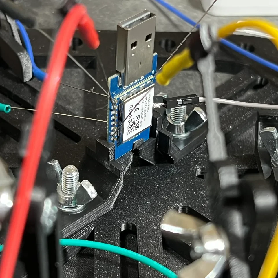
(Click to enlarge)
Solder the Necessary Wires:
To work with the WBR3, you’ll need to solder Dupont wires to the following pads:
| WBR3 Pin | VCC | GND | A_16 (LOG_TXD) | A_15 (LOG_RXD)* | RXD | A_0 | EN |
*A_15 (LOG_RXD) is located on the underside of the WBR3 module.
Use fine soldering wire and a soldering iron to attach Dupont wires to the correct pads on the WBR3 module. Be careful not to apply too much heat, as you could damage the module.
(Click to enlarge)
Connect to a Breadboard
Once the necessary wires are soldered, carefully place the WBR3 module onto a breadboard. Ensure that the module is securely seated and that all connections are stable.
Power Supply and UART Adapter:
Once the necessary wires are soldered to the WBR3, connect the module to the power supply and UART adapter via Dupont cables as follows:
| WBR3 | UART | Description | Purpose | A_16 | UART RX | Connect to USB UART RX | Receives data from WBR3 for communication/debugging | A_15 | UART TX | Connect to USB UART TX | Sends data/commands to WBR3 | A_0 | — | Connect to 3.3 V power supply | Enables bootloader mode during flashing | RXD | — | Connect to 3.3 V power supply | Enables bootloader mode during flashing | VCC | — | Connect to breadboard 3.3 V power supply | Powers the WBR3 module | GND | — | Connect to breadboard ground (GND) | Completes electrical circuit and common ground reference | — | GND | Connect to breadboard ground (GND) | Common ground reference between UART and WBR3 |
Connection Setup Examples
Note: The images below show the correct wiring connections. Your setup should look similar to these photos. In these images, the brown Dupont cable that is not connected is used for shorting the EN pin to GND during flashing to enter bootloader mode.
Overview of All Connections
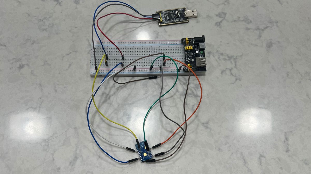
(Click to enlarge)
Same Setup from Another Angle
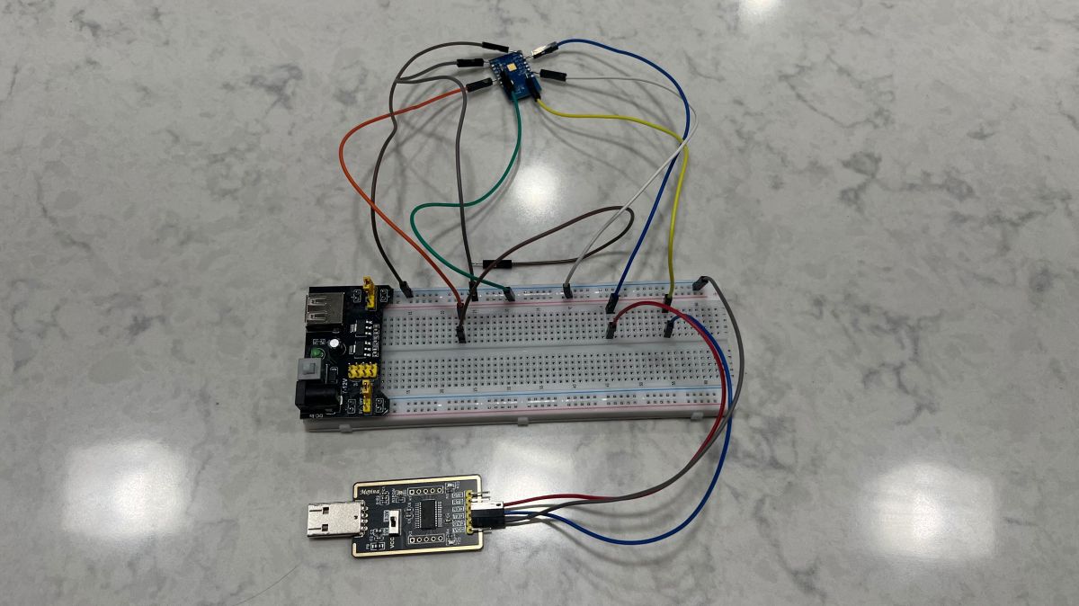
(Click to enlarge)
Close-up of UART Connections
(Click to enlarge)
Close-up of WBR3 Connections
(Click to enlarge)
Flashing the WBR3 with OpenBeken (Firmware Installation) (Images coming soon)
Requirements:
• USB-to-UART adapter (3.3 V logic level)
• Stable 3.3 V power source (for example, an AMS1117 regulator)
• Soldering tools or a probe jig to access UART and boot pins
• OpenBeken firmware .bin file for RTL87X0C
• AmebaZ2 Download Tool (PG Tool v1.2.47 or later)
• A basic understanding of the WBR3 pinout (see the “Prepping the WBR3 for Use” section above)
Download the Firmware:
You can find the latest OpenBeken firmware for the WBR3 on GitHub: OpenBeken GitHub Releases
• Scroll to the Assets section under the latest release
• Download the correct firmware file for RTL87X0C
○ OpenRTL87X0C_x.xx.xx.bin is used for flashing via UART
○ OpenRTL87X0C_x.xx.xx_ota.img is used only for OTA updates after OpenBeken is installed
Only the .bin file is needed during the initial flashing process. Save this file to your computer so it can be loaded into the PG Tool.
Flashing Instructions:
• Wire your USB-to-UART adapter to the WBR3 as described in the “Prepping the WBR3 for Use” section. Do not apply voltage to the RXD and A_0 pins yet
• Launch the PG Tool (version 1.2.47 or newer), select the correct COM port, and make sure the target chip is set to RTL87X0C
• When the tool prompts you to enter bootloader mode, apply 3.3 V to both RXD and A_0. Then briefly short the EN pin to GND. The tool should recognize the WBR3 and establish communication
• Use the tool to create and save backups of the original firmware. Make sure to back up both the full flash (approximately 2 MB) and the ROM (approximately 384 KB). Store these backups in a safe location
• Load the OpenBeken .bin file you downloaded earlier into the tool. Select the erase option if prompted, then click Write to begin the flashing process. Wait until the flashing completes successfully
• Remove 3.3 V from RXD and A_0. Then briefly short the EN pin to GND again to reboot the module. The WBR3 should now start running OpenBeken
OpenBeken Wi-Fi Setup and Configuration (Images coming soon)
After flashing and rebooting the WBR3, complete the setup by following these steps:
• On your computer or phone, connect to a new Wi-Fi network named OpenRTL87X0C_XXXXXX
• Open a web browser and go to http://192.168.4.1. This opens the OpenBeken configuration interface
• Scroll to the WiFi Setup section
• Enter the name (SSID) and password of your home Wi-Fi network
• Optionally enter your MQTT settings if you plan to integrate the device with Home Assistant or another platform
• Click Save and then click Reboot
After the reboot, the WBR3 will disconnect from the temporary access point and attempt to join your home Wi-Fi network.
Integration with Home Automation Platforms
This section explains how to integrate the WBR3 module running OpenBeken into your Home Assistant setup using MQTT. It focuses on configuring MQTT, enabling entity auto-discovery, and connecting OpenBeken datapoints to Home Assistant entities for control and monitoring.
Topics may include:
• Setting up MQTT in OpenBeken
• Enabling Home Assistant MQTT discovery
Troubleshooting and Tips
This section highlights real-world issues encountered during the flashing and setup process, along with solutions and useful tips that made things easier.
Topics may include:
• Helpful OpenBeken console commands for testing and debugging
• Fixing UART connection or communication failures

With over 20 years of experience in IT, I have a passion for smart home automation, building efficient systems, and exploring creative solutions through custom hardware and software. I enjoy working with Node-RED, ESP-based devices, and Home Assistant, keeping everything local and secure without relying on cloud services.
I spend a lot of time designing for 3D printing. Most of my projects are upgrade parts, functional tools, or decorative items that solve everyday problems. You can check out some of my work on my Printables profile.
Drumming is one of my newer interests. I am still learning, but it has become a great way to reset and take breaks from the screen. I also enjoy working on radio-controlled cars, home improvement projects, and exploring anything that lets me create or automate.
After many years of using Windows, I finally made the full switch to Linux a few years ago. I had tried to switch before, but always ended up going back. This time it stuck. Now I use Linux Mint or Ubuntu for my daily work, and other distros like Alpine, Debian, and CentOS for servers and specific projects.
Sharing knowledge is something I really value. It helps others, reinforces what I learn, and adds to the growing community of makers and tinkerers. Balancing hobbies with professional life can be a challenge, but I enjoy the process of learning and exploring new things.
Stay forever curious. dressyspider wrote 83 posts with rating 10 . Live in city Phoenix. Been with us since 2025 year.
Comments
Great work @dressyspider! I have 6 of these units and a couple of spare dongles. I see some flashing in my future. Question: I read that as soon as the new mqtt device is discovered, a new climate entity... [Read more]
Sorry for the delayed response! Yes, you can control the vertical and horizontal vane swing. You can add them as "features" on the thermostat card to keep them readily accessible, or access them via the... [Read more]