logo elektroda
logo elektroda
X
logo elektroda

Short-circuit power of a 15/0.4 kV transformer - how to calculate it

Qurak 32343 13
ADVERTISEMENT
Treść została przetłumaczona polish » english Zobacz oryginalną wersję tematu
  • #1 9654154
    Qurak
    Level 17  
    Hello

    I have two 15/0.4 kV transformers at work with a capacity of 800kVA each. During the last survey and measurements, it was recommended to hang plates in the transformers' compartments with the transformers' short-circuit power and with the cross-section of the earthing switches. On the RWN switchgear we have such a plate posted.
    I'm not sure if I'm counting this power correctly, so please have someone check it for me and if necessary help me calculate it.
    From the documentation of the transformer and the nameplate I read that:
    short-circuit voltage Uz = 5.74%
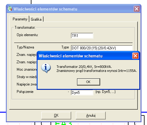
    nominal current In = 1155A

    I assumed, That since during a short circuit at Uz I have a current on the secondary side In then at full voltage on the primary side when the secondary side is shorted, the current will be Is = 100/Uz * In. This gives Iz = 34.843 kA and multiplying this by the voltage on the secondary side of 400V I would get Sz = 13.937 MVA or about 14MVA.

    Did I approach the subject correctly or should it be calculated in a different way?

    I'm counting on help

    Greetings
  • ADVERTISEMENT
  • #2 9654316
    HeSz
    Electrician specialist
    Hello
    The method of calculation is in PN-EN 60909-0:2002.(in English and French- unfortunately)
    For the calculation you need:
    1. Short circuit parameters of the supply network ( S, R, X, R/X)
    2. Parameters of power cables ( R, X)
    3. Parameters of the transformer ( R, X - to be calculated if you know uz, Pcu, Pfe)
    The grounding device is selected according to Itz (equivalent thermal current)
    Unfortunately, I am away from home and I will be able to provide more accurate formulas after July 3 (if by then there are no people willing to help)
    Greetings.
  • Helpful post
    #3 9659467
    pm.001
    Electrician specialist
    Hello
    All nice but is actually such an accurate value obtained by the given parameters necessary in this case?
    I suggest reading the nast. thread
    greetings
    pm001
  • ADVERTISEMENT
  • #4 9663334
    HeSz
    Electrician specialist
    Hello.
    In my previous workplace, earthing switches 2x13.5 kA were used - because so "once, someone estimated". After making calculations, it turned out that one 9.5 kA earthing switch was enough. The plant was left with a reserve of earthing conductors for several decades.
    But dread to think what could happen if the "estimation error" worked the other way. Do not underestimate the calculations
    Greetings.
  • #5 9673575
    Qurak
    Level 17  
    Sorry colleagues that I'm only now responding

    Kolego pm.001 according to what you gave me in the link it comes out that I intuitively almost well looked for the solution. Out of haste I completely forgot about that root of 3 :oops: . It comes out that the power I estimated multiplied by √3 will give me what I need i.e. Szw will be about 24.3 MVA.


    On the other hand, however, I'm curious what the exact calculations that HeSz will show. If you can please help me I am patiently waiting after July 3. I just hope that I will be able to provide all the necessary data for calculations.

    What about earthing conductors we have in the plant with a cross-section of 35 mm2 and such we use (both on the medium voltage and low voltage side). Such a condition has been "always" but now I became responsible for it and I would like everything to be as it should be and, above all, to ensure safety in the work. On the RWN switchgear we have a short-circuit power of 150MVA and grounding of 35 mm2 (so it is on the posted plate). I will have a request to assess whether these earthing switches are selected correctly.

    Thank you for your interest in the topic and your help. I look forward to further help and greetings
  • #7 9680030
    Qurak
    Level 17  
    Fellow kkas12 I don't really understand your statement with these transformer properties. Could you please explain to me how I should understand your answer

    Greetings
  • #8 9699594
    kkas12
    Level 43  
    Hello!

    Today it's probably "over" anyway, but we'll theorize.

    You have a transformer with Pn=800kVA, which gives In=1155A.
    How did you come up with 2kA?
    Parallel operation?
    With the earthing switches on the two trays in place, it is unlikely that someone on medium would switch on two transformers at the same time. That they should not be attached is stated in health and safety regulations. Moving on. For parallel operation, you can assume a current of 2kA, but then you don't have the option of putting earthing switches on. It is the equipment that must be selected for such a short-circuit current, if the instructions provide for parallel operation of traf.
    Further.
    With one hit as already stated here, you have overestimated the short-circuit current twice. Further on, this is just the result of incorrectly assuming the output data. Reduce the transformer's znamian current and you'll have it all figured out.
  • ADVERTISEMENT
  • #9 9700610
    Qurak
    Level 17  
    Hello

    It is not yet "over" and thank you for the clarification. The topic is not over because I have not yet explained everything to myself. Yes the nominal current I gave incorrectly and is indeed 1155A. Sticking to the calculation method given by my colleague pm.001 then for the correct current I came out with power Szw = 13.94 MVA and this is probably already the correct result. I think that in accurate calculations taking into account the impedance of the connections this power will always be less. Therefore, on the plate I will put the value of 14 MVA because it is very close to the calculated value and the plate is intended to make you aware of the order of magnitude of short circuit power. Or do I have to specify exactly the power as calculated? Please advise.

    The issue of grounding devices remains. During the winter season, both transformers work in parallel and grounding devices are not used then. In contrast, during the summer season one transformer is sufficient. We use one transformer once and the other transformer once, and each transformer works for the appropriate number of days and then switches to the other transformer. Then we use grounders - during maintenance and cleaning of the non-working transformer. During the operation of one transformer, the lower voltage of the other transformer is switched off and disconnected in the GRNN switchgear and the upper voltage is disconnected in the RWN switchgear. During the work, we put grounding devices on the rails in the trafo chamber on the upper and lower voltage side. We give two for safety although the earthing switch is always visible from the work site anyway. There is one brigade that does the work so there is no possibility for someone to attach a second transformer during the work. I think I briefly explained the nature of the work of our equipment.

    I have two more questions:
    1. Why did you write colleague that health and safety regulations prohibit the attachment of two transformers?
    2. How to count the cross-section of the earthing switch? It was mentioned that I need replacement thermal current . How to determine it


    About short circuit power and its rough calculation I have already understood everything. All that's left for me is the subject of the cross-section of the grounding electrode. When I will know this, then I will make the plates and no one will accuse me that I took the values from outer space because I will be able to prove how I calculated it.

    Thank you colleagues for your help so far and please provide further clarification.

    Greetings
  • ADVERTISEMENT
  • #10 9701192
    kkas12
    Level 43  
    Of course, the traffic can be switched off.
    Now what does the company's operating instructions say?
    Does a trafo switched off for 3 months have to be tested again?
    Maybe such tests need to be carried out only after the trafo has been out for a year? And what would happen if the trafo "walked" at idle?

    Health and safety regulations dictate that work should be performed without exposing people to danger. Thus, placards should be hung " NO ON " on trafo breakers. In your case, you should also hang a placard " Grounded ". And that's why an electrician seeing such info won't switch on the transformer.

    A cross section of 35mm2 has about Icw=13kA. 50mm3 cross section has about 18kA. This is already enough information?

    And the calculation of Icw is approximately as follows:
    From paragraph 434.3.2 of PN-IEC-60364-4-43 there follows the ratio: I² × t = k² × S², where I is the effective value of the short-circuit current (i.e., Ik), S is the cross-sectional area of the cable core in [mm2] and k is a constant depending on the cable material and its insulation. From the above ratio, Icw(0.1 s) can be derived by substituting a value of 0.1 s in place of time t.
    This results in the inequality: Ik² × Ttr
  • #11 9701266
    Qurak
    Level 17  
    We have a transformer idle time of no more than 1 month precisely so that we don't have to do transformer tests before switching back on. On the other hand, idling is the production of idle losses of the transformer, and although they are relatively small (I don't remember exactly, but less than 2kW), for a month a few nice kWh will accumulate :)

    I didn't write about this either, because it's obvious to me - the appropriate plates are posted on the switching fittings both in the RWN and GRNN switchgear.

    From the calculations it comes out to me that we have a short-circuit current of the transformer above 20kA so the earthing fittings you have have too small cross section !!! From the values you have given, it comes out that we need to have an earthing switch with a cross-section larger than 50mm2.
    One more point - The transformer has protection on the medium voltage side of 20A. Will a 35mm2 cross-section earthing switch on the transformer from the upper voltage side break the circuit (blow the fuse) if the transformer is not allowed to be switched on? It seems to me that yes, and it will happen in a very short time (low resistance) but please give me a hint.


    I cannot understand the transformation to the final inequality. I don't know where Ttr comes from and what is it? Please explain and I take myself to read the standard.

    Thanks for the answers to my questions.
    Greetings
  • Helpful post
    #12 9703221
    kkas12
    Level 43  
    Hello!

    The short-circuit current of the 800kVA transformer is at a level barely exceeding 18kA, if we are talking about the instantaneous three-phase short-circuit current (rms value). The peak short-circuit current is about 2.5x higher. That's why I gave some cross sections, giving some food for thought.
    At medium voltage, the cross section of the grounding conductor is sufficient. It can handle even 25mm2. After all, the insert itself has the property of limiting short-circuit current.
    Ttr is nothing more than the shutdown time of the protective element (disconnection of the short circuit site from the power source).
    And I guess in closing, it seems to me that you are trying with apothecary precision to determine something that I don't know if it makes sense. The use of a larger cross section will only improve the dynamic properties of the grounding device. That it's a little more expensive is a matter for the accountant.
  • #13 9703720
    Qurak
    Level 17  
    Well, that explained. Probably, earthing switches were selected and bought for the upper voltage of the transformer and out of momentum (probably a long time ago) the team began to use them also on the lower voltage side. Hence my suspicion that the existing earthing switches are incorrect in terms of cross-section. In addition, the gentleman doing the measurements of the switchgear recommended that the appropriate plates should appear in the traf chambers - and so this topic arose. Due to the fact that I have to deal with electricity (installations, measurements, protections, etc.) and I have never had the need to calculate short-circuit powers and cross-sections of earthing switches, I want to know these issues well enough to be able to explain to everyone where I got such and not other values.
    When it comes to apothecary accuracy :) then in such matters I prefer to give a value that is a lot overstated than a bit understated - this is about safety.

    My calculations came up with a short-circuit current of a little over 20kA and short-circuit power of almost 14 MVA (and such I will write on the plate) while, as my colleague wrote earlier earthing conductor I will use 50mm2 (on the lower voltage side) a accountants should worry about where to get the money :)

    Thank you all for your help and explanations and especially colleagues pm.001 and kkas12 . I hope no one in the company will try to undermine the reliability of my calculations ;)

    Greetings

    PS I am still waiting to study some standards :) .

Topic summary

The discussion revolves around calculating the short-circuit power of two 15/0.4 kV transformers with a capacity of 800 kVA each. The author initially calculated the short-circuit current using the transformer's short-circuit voltage (Uz = 5.74%) and nominal current (In = 1155A), resulting in an estimated short-circuit power of approximately 14 MVA. However, further contributions highlighted the importance of accurate calculations, referencing standards such as PN-EN 60909-0:2002 for short-circuit parameters and grounding device selection. The author acknowledged a miscalculation and confirmed that the correct short-circuit power should be around 24.3 MVA when considering the square root of three. Discussions also included the adequacy of earthing switches and grounding conductors, emphasizing safety and compliance with regulations. The need for accurate labeling of short-circuit power on transformer plates was also noted.
Summary generated by the language model.
ADVERTISEMENT