logo elektroda
logo elektroda
X
logo elektroda

Excessive Heating in ETD49 3C90 Core Pulse Transformer Primary Winding at 50kHz: Solutions

dannnek 8094 32
ADVERTISEMENT
Treść została przetłumaczona polish » english Zobacz oryginalną wersję tematu
  • #1 16082003
    dannnek
    Level 13  
    Hello,
    I have a problem with excessive heating of the primary winding in the converter, namely after 10 minutes of operation it reaches a temperature of over 140 C.

    The transformer I built is based on the ETD49 3C90 core without a gap, it works in a half-bridge system with f=50kHz, the primary winding has 39 thick-faced turns, the whole thing is powered from the mains voltage, rectified, i.e. 320V, on the secondary side I take 120V and 5A .

    Is this temperature normal or should I use some trick? E.g. increase the gap or increase/decrease the number of turns or increase the core?
  • ADVERTISEMENT
  • Helpful post
    #2 16082622
    komatssu
    Level 29  
    Write something more about this "fat face" - what is its cross-section?
  • #3 16082689
    dannnek
    Level 13  
    120 wires with a diameter of 0.1mm, i.e. 0.942mm2.
    Assuming 3A/mm2, the wire appears to be good.
  • #4 16092869
    dannnek
    Level 13  
    What should be the current flow on the primary winding?
    - should it resemble a triangle or a rectangle?
  • #5 16093039
    hajy
    Level 22  
    Hello

    The course of the current on the primary winding will depend on the current that is taken from the secondary winding, and this depends on whether you have a choke behind the rectifier or not and the inductance of this choke.
    In my opinion, you used lice at this frequency unnecessarily, and the number of turns on the primary one is also definitely too large.
    Give a little more information, because pulling out every detail doesn't make things any easier.
    A schematic would be helpful.
    Regards, Romek
  • #6 16093167
    dannnek
    Level 13  
    So, the diagram in the attached photo, half-bridge converter, UC3525 controlled keys, +320V power supply - rectified mains.
    On the secondary side, there is a voltage multiplier, a 470uH output choke and a 1uF filtering capacitor.

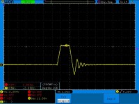
    I measured the current behavior on the primary side without a multiplier (photo #2), with a normal 500 Ohm resistive load, 40% duty cycle and the current looks bookish. The scale on the oscillogram corresponds to the ratio of 1V to 1A.
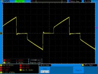
    After connecting the multiplier to the secondary side and a load of 500 Ohm, the current waveform looks like in picture No.3. Of course, the filling reduced to 20% due to the duplicator in the system.
  • Helpful post
    #7 16095289
    hajy
    Level 22  
    For me, both waveforms look correct.
    As you write, the first graph looks like a book, the second one too, because you have a capacitive load, the choke is only behind the capacitors. What prompted you to use a duplicator unnecessarily complicating the system. In general, multipliers work well where you need high voltage at low currents, you don't have any of these conditions
    Give a photo of the transformer and describe exactly how you wound it.
    Regards, Romek
  • #8 16096384
    dannnek
    Level 13  
    I used the duplicator because I also need a voltage of 1kV, a current of 0.5A. Unfortunately, in terms of capacitive load, you are absolutely right, the capacitance or rather the reactance of the capacitor is a very large load. Testing the transformer itself on a resistive load of 500 Ohm, the windings and the entire transformer reach a temperature of 45C after 30 minutes, and with the multiplier and load after 15 minutes it is already over 120 C. Unfortunately, I do not have much experience with multipliers, but I am surprised by such behavior of the system, maybe too large capacitance or wrong type of capacitors. Any suggestions?
    The transformer is wound on the original carcass, first the secondary winding and then the primary winding, separated by 3 layers of tape.
    With the choke it's my mistake, I threw it behind the multiplier before the filter capacitor.
  • ADVERTISEMENT
  • Helpful post
    #9 16096713
    hajy
    Level 22  
    Hello

    Divide the primary winding into two parts and put the secondary winding in between, how can you be sure that only the primary is heating up?
    Write how many layers the primary and secondary windings have, and what the secondary is wound with.
    Heating is clearly caused by losses in the winding, and as I wrote, the primary winding is too large, half of it could do it.
    And you do realize that putting the load behind the multiplier, the power dissipated in it is almost four times greater than without the multiplier.

    Regards, Romek
  • #10 16096905
    dannnek
    Level 13  
    I checked the temperature of the windings with a thermocouple, inserting it into the hole in the carcass, and it clearly turned out that the primary side heats up more and faster.
    As for the windings, the primary side has 39 turns with face 120*0.1, i.e. 0.94mm2, and the secondary side has 141 turns with face 7*0.3, i.e. 0.49mm2.
    The primary side is 3.5 layers, while the secondary 3 are laid quite tightly.
    I will perform tests with fewer turns and with the division of the primary winding as you advise. When it comes to power, I control the current and voltage so that both with and without the multiplier there is no more than 500W.
  • #11 16098769
    dannnek
    Level 13  
    I think that the issue of heating the windings is partly solved, according to the oscillogram marked as 3, you can see that in the flat upper part the core is saturated and the winding acts as a heater. I reduced the number of turns on the primary as you suggested, and I introduced a gap in the core, the temperature of the winding is about 50 C. The current on the primary changes depending on the capacity in the multiplier, capacitance greater than 100nF is deadly for transistors. The second thing is the pop and sizzle of the hitch, what could it be caused by? The third thing I wanted to ask is the selection of the output choke, what is the rule so that it does not get hot?
  • Helpful post
    #12 16100286
    jarek_lnx
    Level 43  
    The choke in half-bridge converters is used because the half-bridge itself with the transformer constitute a rigid source of rectangular voltage, so changing the filling does not change the voltage at the output, if it is possible to reduce the voltage, it is mainly due to overload and winding resistance losses.

    Quote:
    on the secondary side I take 120V and 5A.
    While nominally it was supposed to be 1kV 0.5A? If you put a regular mains transformer so hard that the current reaches 10 times the nominal current, or the voltage drops to 12% of the nominal, no one will be surprised that smoke will come out of the transformer, then why are you surprised that yours is overheating?

    A choke with a diode and a capacitor at the output, in half-bridge, full bridge and forward systems, works the same as in a buck system, the voltage before the choke has a constant amplitude and the variable fill only after the choke the voltage becomes dependent on the fill.

    If you want to keep the voltage doubler system, the voltage adjustment should be done before the half bridge.

    You made two mistakes below:
    Quote:
    according to the oscillogram marked as 3, you can see that in the flat upper part, the core is saturated and the winding acts as a heater.
    Whether the core is saturated does not depend on the load, if it is not saturated with a large filling (no-load oscillogram), it is certain that it is not saturated with a small one (loaded oscillogram).

    Quote:
    I reduced the number of turns on the primary as you suggested, and added a slot in the core,
    Both changes lead to an increase in the magnetizing current (but you had no problems with that).
    In this topology, if you drive to saturation (nothing like that happened), introducing a saturation gap won't eliminate it (a transformer is not a choke and different rules apply here)

    The division of the primary winding recommended by my colleague above will improve the stiffness of the transformer, which will make the system with a design error - without a choke - work even worse.
  • #13 16103127
    dannnek
    Level 13  
    Thank you for your comment,
    additionally, I will start with the rectification, the nominal voltage is 500V and 1A, I used the multiplier to achieve 1kV and 0.5A. Sorry, there was an error in my first post.
    - regarding the oscillogram No. 3, I do not fully understand why the characteristic is flat in the upper part, the scale on the 2nd and 3rd oscillogram is 2 and 5A per division, respectively,
    - how well do I conclude the pulse transformer in the converter should work without a gap?
    - and the current waveform in the primary winding shapes the output choke.
  • Helpful post
    #14 16104115
    komatssu
    Level 29  
    A rectifier with a voltage doubler will work properly in an LLC resonant converter, where the choke is in front of the transformer. Such power supplies are commonly used in microwave ovens to power magnetrons.
  • #15 16110469
    dannnek
    Level 13  
    To be sure, tell me whether the transformer in the impulse power supply can have a gap or not?
  • Helpful post
    #16 16111779
    jarek_lnx
    Level 43  
    Quote:
    To be sure, tell me whether the transformer in the impulse power supply can have a gap or not?
    The transformer should not have a gap, the gap is needed in elements that must accumulate energy or work with a DC component, i.e. in chokes. Only in the flyback the "transformer" has a slot, although in fact it is a choke with many windings.
  • #17 16118264
    dannnek
    Level 13  
    Thank you for your answer.
    I have a few more questions. Estimating the number of turns on the primary side of the transformer based on the page:
    http://schmidt-walter-schaltnetzteile.de/smps_e/hgw_smps_e.html
    I have small doubts about the obtained result, namely I am interested in the ETD49 core, the parameters that I provide: voltage Vin=325V, f=50kHz, output voltage Uout=500V, current Iout=1A.
    As a result, I get an inductance of L = 931.8uH with the number of turns 39 primary, 130 secondary. From the formula AL=L/N^2 we get the constant AL=612nH/N^2. However, the catalog note states that the AL for the ETD49 3C90 core is 4200nH/N^2, whether these calculations from the website suggest a gap in the core or something else should be taken into account.
  • ADVERTISEMENT
  • Helpful post
    #18 16124952
    _lazor_
    Moderator of Designing
    You can always test the core by winding 10-20 windings on the core and power half the bridge from the autotransformer, connect the core with the test winding to the output and check what current flows through it through the transformer. This will empirically show how many volts you can give per turn.

    I wonder what you wrote about photo number 3. When the core is saturated, a short circuit occurs and the current is mainly limited by resistance (empirically proven, mosfets will explode well), the question is what limits the current at your place?

    The multiplier accumulates energy equal to (u^2*C)/2, so as you increase the voltage at the output, the energy accumulated in the multiplier is significant, and thus the system mainly works on a short circuit.

    To control such systems by frequency and not fill (voltage and current at the output), resonant systems (LC at load or LLC (output as voltage source) or LCC (output as current source) with lighter load) must be used.

    Did you assume that the winding wire has an enamel that thins the cross-section of the wire a bit?
  • #19 16125434
    dannnek
    Level 13  
    A valuable suggestion, I will check the system with the autotransformer, and more specifically how many V / turn. And as for graph 3, after about a minute the MOSFETs got a complete short circuit and you know what's next.
    I will look at the LLC and LCC configurations, but I will not let go of the multiplier system until the end.
  • Helpful post
    #20 16126093
    Urgon
    Level 38  
    AVE...

    I repeated your calculations and it actually gives such numbers for EDT49. However, have you noticed that this table entry is marked as too small a core for this application? ETD54 core is suitable. But raise the frequency to 100kHz, wind 30 turns of primary winding and 100 of secondary windings and it should handle this core...
  • ADVERTISEMENT
  • #22 16136148
    dannnek
    Level 13  
    Good evening,
    thank you for your commitment, the programmer is very interesting, I will certainly use his suggestions.
    Regarding the ETD49, according to SFDT2010 it is able to transfer 740W at 50kHz.
    I will perform all tests from tomorrow, so I will let you know what the results have been, I have the ETD54 and 59 cores done, so it's just a matter of checking in practice.
    Regards
  • #23 16168595
    dannnek
    Level 13  
    Hello, tests done, unfortunately ended in failure. In a system with a voltage doubler, each transformer heats up.
    I'm going to make a resonant converter. Colleagues, maybe you could advise a specific type that is worth doing LLC, LCC, LLCC?
  • Helpful post
    #24 16168711
    _lazor_
    Moderator of Designing
    Increase the number of windings on the primary or change the core to a larger one. If you work with too much induction (B), the core will always get hot. The current flowing through the unloaded transformer should be minimal (a dozen or so mA), if you have more, it means that you either folded the core or you have too few turns on the primary one.

    Unfortunately, the resonant system will not prevent the core from heating up, quite the opposite. Resonant circuits have other advantages, in popular solutions it is mainly about minimizing losses on key commutation.
  • #25 16184301
    dannnek
    Level 13  
    Hello, I have a question about a resonant converter, e.g. LLC, can you adjust the output voltage by changing the keying frequency? If so, to what extent can it be adjusted?
  • #26 16184516
    _lazor_
    Moderator of Designing
    Unfortunately, it can only be adjusted under load and only to a certain extent. The higher the goodness of the resonant system, the easier it is to adjust, but Q at the level of 2-3 is already a lot. Maybe dedicated drivers for LLC somehow solve this problem, unfortunately I have never built from ready-made drivers dedicated to LLC.
  • #27 16186867
    dannnek
    Level 13  
    hmm, how are converters with regulated DC output made?, the filling control itself is a big loss, a square wave on the output with a large amplitude, etc.
  • #28 16186940
    _lazor_
    Moderator of Designing
    That is why linear laboratory power supplies are still so popular, because they provide the easiest and very accurate adjustment option.

    I saw resonant converters adjustable from 0V (up to 600V), but it was a private production of a certain designer, where he used his own control algorithms.
  • #29 16187116
    dannnek
    Level 13  
    well, yes, but a linear power supply is low efficiency and it is impossible to obtain 500V
  • #30 16187242
    brofran
    Level 41  
    dannnek wrote:
    but a linear power supply is low efficiency and it is not possible to obtain 500V

    I've seen ones that gave 10 kV (insulation breakdown meters - so-called KENETRONS). :D

Topic summary

The discussion revolves around excessive heating in the primary winding of a pulse transformer using an ETD49 3C90 core in a half-bridge converter operating at 50kHz. The user reports temperatures exceeding 140°C after 10 minutes of operation. Various contributors suggest potential solutions, including reducing the number of turns on the primary winding, introducing a gap in the core, and optimizing the choke placement. The user confirms that the primary winding heats more rapidly than the secondary and discusses the impact of a voltage doubler on the system's performance. The conversation also touches on the importance of current waveforms, core saturation, and the implications of using a resonant converter. Ultimately, the user plans to test configurations with different core sizes and winding arrangements to mitigate heating issues.
Summary generated by the language model.
ADVERTISEMENT