Hey everyone, I was looking, I was looking, but I didn't find it, and it's still difficult to understand the English scribbles.
I turn to automation engineers, because I think that it is quite a close issue for automation.
To the point - I have a problem with understanding the operation of strain gauges.
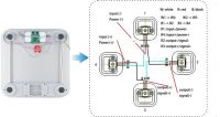
I use four sensors that can be found in virtually every electronic bathroom scale. They look like this:

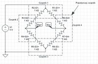
I have drawn a diagram of such a weight:

And now I have a question because I understand that it gets a variable voltage at the output depending on the pressure on the sensors, I know that.
I also know how the Wheatstone bridge works, but I'm not sure what it looks like here ...
As I figured it out, for each sensor there is one resistor (wire?) On which the resistance does not change and one on which changes occur and receives a different voltage at the output.
Further, looking at my diagram, do I understand correctly that for this bridge R2, R3, R6 and R7, respectively, is variable and the rest is constant? I mean, as with the Wheatstone bridge? Then you can simplify R2 and R3 as sum etc. in pairs respectively and I get a normal Wheatstone bridge?
Maybe a trivial question but I prefer to be sure
Here a link from the English site - https://electronics.stackexchange.com/questio...e-bridges-from-a-bathroom-scale/199470#199470
I turn to automation engineers, because I think that it is quite a close issue for automation.
To the point - I have a problem with understanding the operation of strain gauges.
I use four sensors that can be found in virtually every electronic bathroom scale. They look like this:

I have drawn a diagram of such a weight:

And now I have a question because I understand that it gets a variable voltage at the output depending on the pressure on the sensors, I know that.
I also know how the Wheatstone bridge works, but I'm not sure what it looks like here ...
As I figured it out, for each sensor there is one resistor (wire?) On which the resistance does not change and one on which changes occur and receives a different voltage at the output.
Further, looking at my diagram, do I understand correctly that for this bridge R2, R3, R6 and R7, respectively, is variable and the rest is constant? I mean, as with the Wheatstone bridge? Then you can simplify R2 and R3 as sum etc. in pairs respectively and I get a normal Wheatstone bridge?
Maybe a trivial question but I prefer to be sure
Here a link from the English site - https://electronics.stackexchange.com/questio...e-bridges-from-a-bathroom-scale/199470#199470


