FAQ
TL;DR: A home-built Single-Ended EL34 stereo amp delivers approx. 8 W/channel and hum under 1 mV; "there is really silence" [Elektroda, woda400, post #8721962] Switchable triode/pentode, ECC82 driver, parts cost ≈ PLN 450 [Elektroda, woda400, post #8721962]
Why it matters: the design shows how low-noise valve sound is attainable on a student budget.
Quick Facts
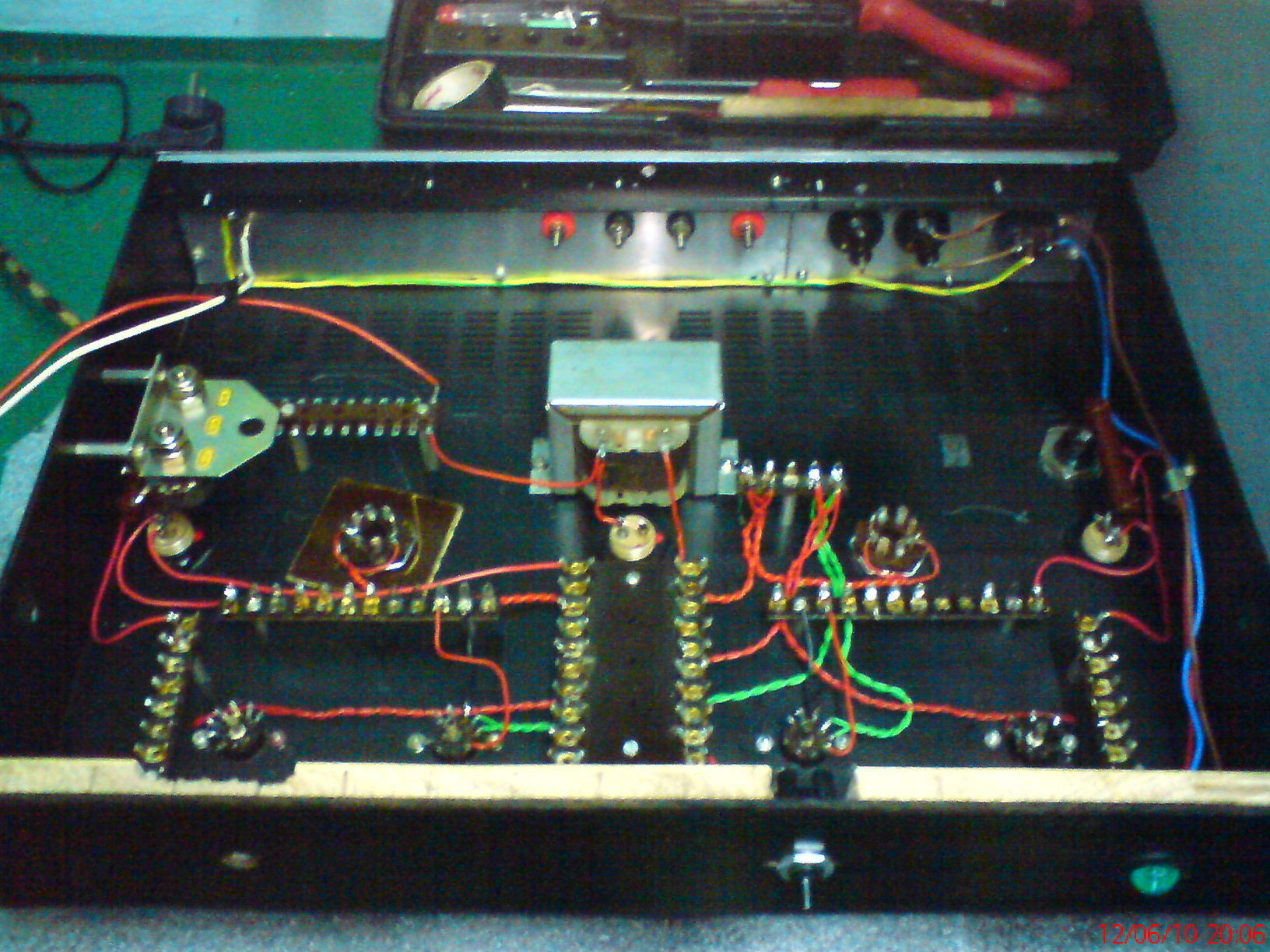
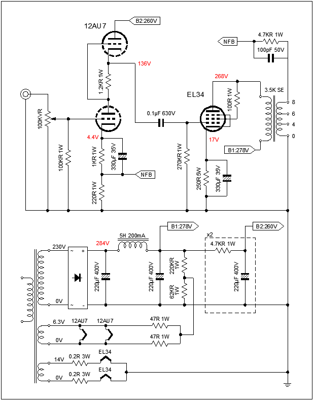
• Topology: SE EL34, triode/pentode switch, ECC82 white-cathode follower preamp [Elektroda, woda400, post #8720160]
• Output power: ≈ 8 W pentode, ≈ 4 W triode (typ.) [Elektroda, woda400, post #8721988]
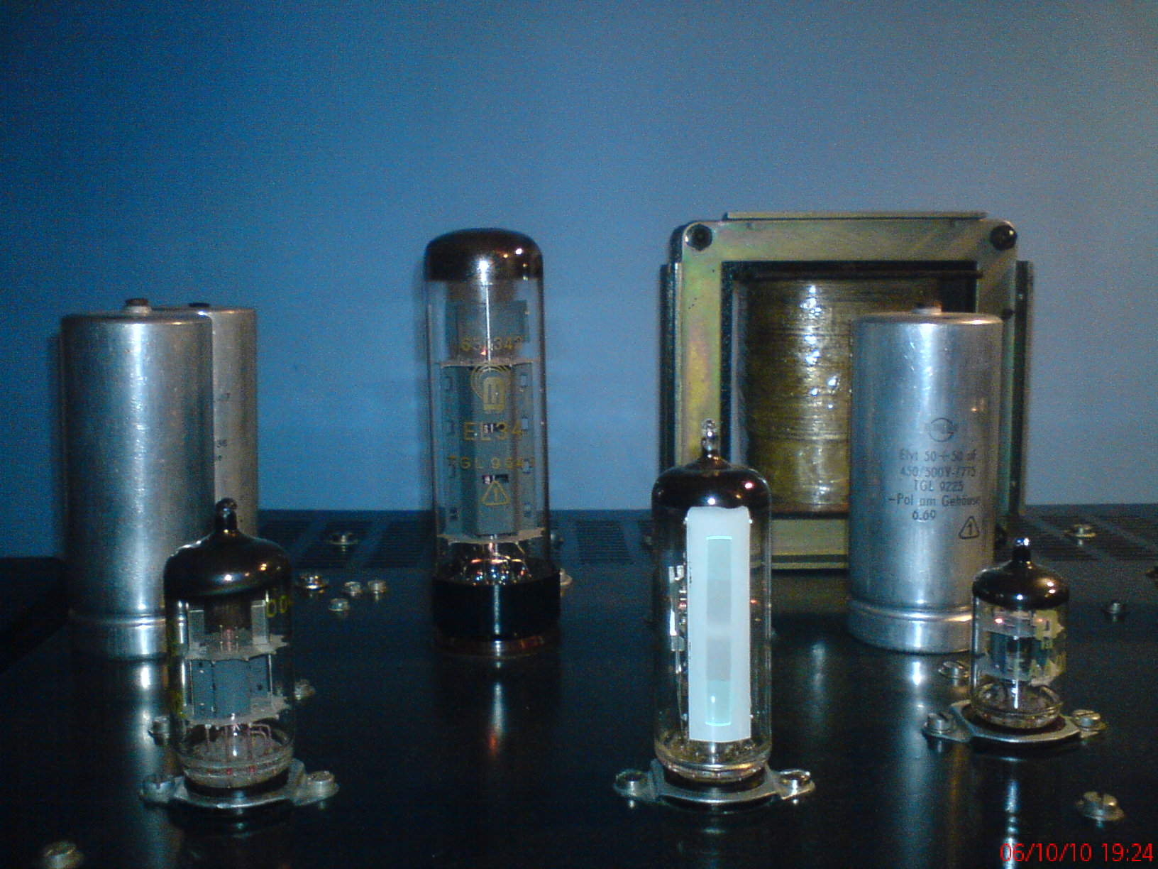
• Anode supply: 270 V first cap, 245 V at EL34 plate, bias –14.5 V [Elektroda, woda400, post #8720160]
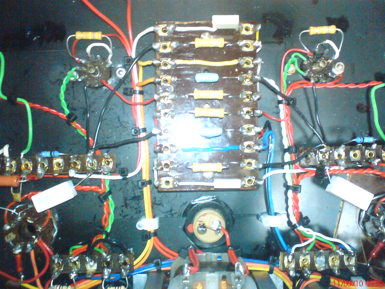
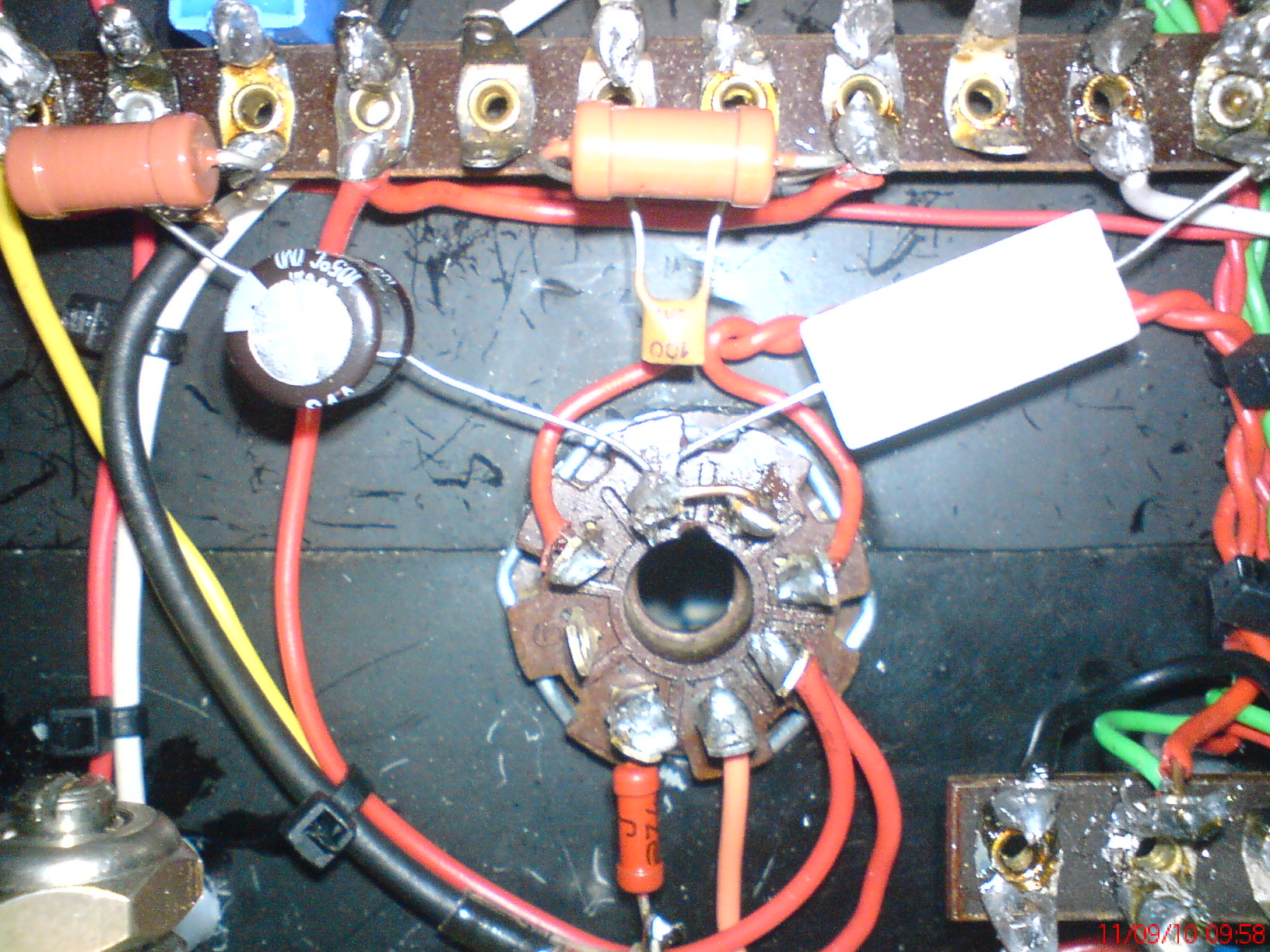
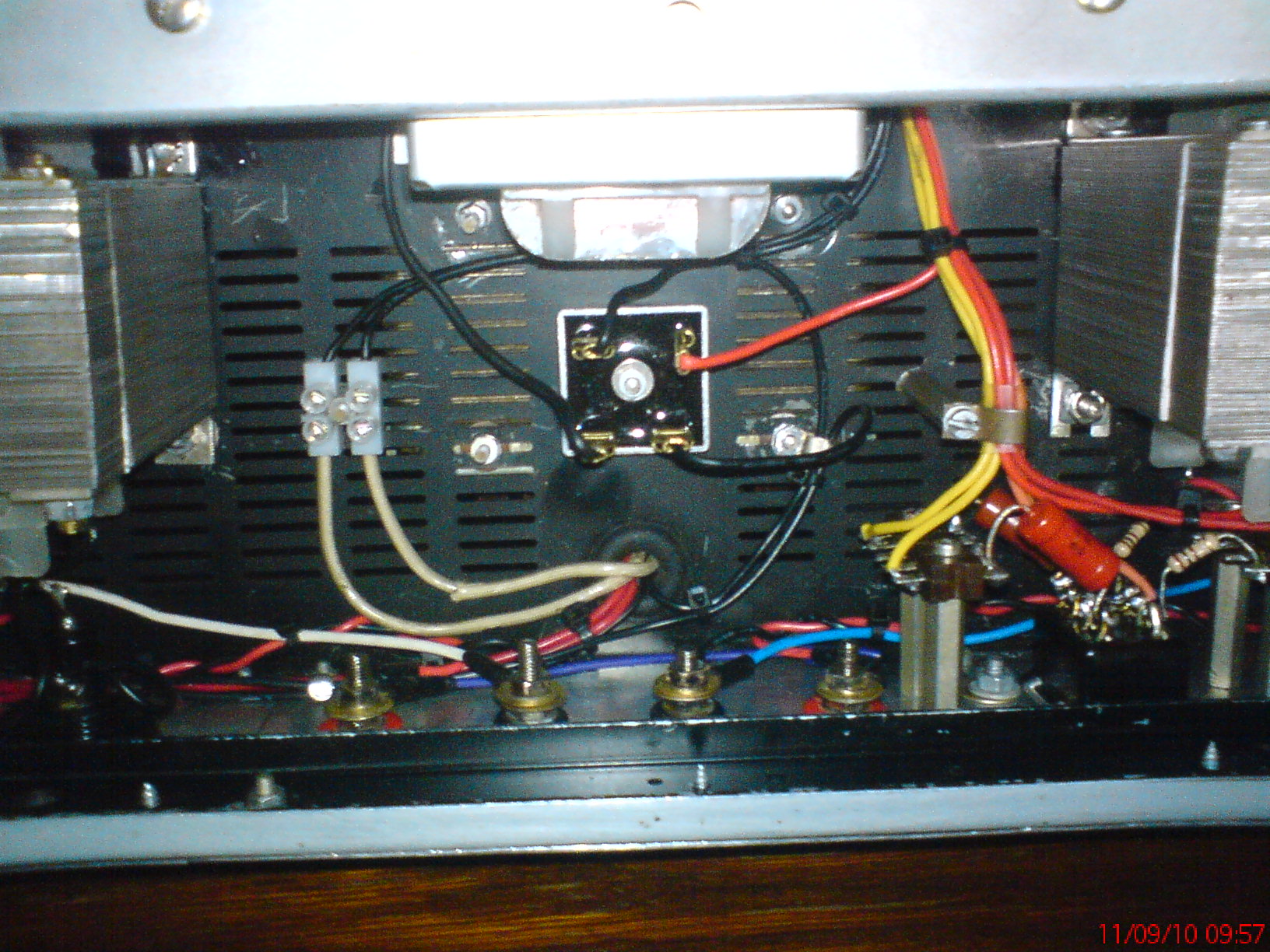
• PSU reservoir: 362 µF total, CLC + CLCRC, 8.1 H/140 mA choke [Elektroda, woda400, post #8720160]
• Build cost: ~PLN 450 including iron and small parts [Elektroda, woda400, post #8721962]
What circuit topology does the amplifier use?
Why was the ECC82 selected as the driver tube?
The builder already owned several ECC82s and found that, in the WK configuration, its µ≈17 gives enough voltage swing to reach –14.5 V grid bias on the EL34 without needing an additional gain stage
[Elektroda, woda400, post #8721962]
How much did the project cost to build?
Speaker output transformers cost PLN 200/pair, the mains transformer PLN 80; total expenditure including passive parts was about PLN 450 (≈ €100)
[Elektroda, woda400, post #8721962]
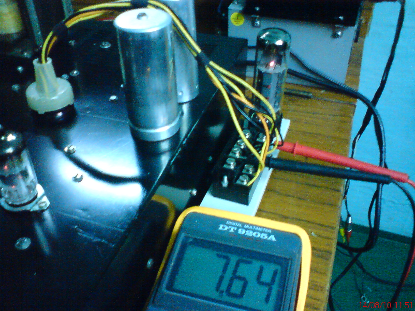
How was hum kept below 1 mV?
- A CLC filter feeds the power stage; a CLCRC feeds the preamp, giving 362 µF total smoothing.
- An 8.1 H choke rated 140 mA reduces ripple.
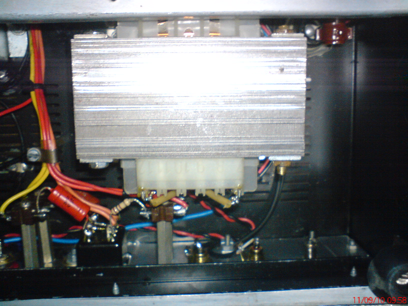
- All cable shields are grounded at one end only, and the metal chassis is the single star ground point.
These measures yielded measurable hum of “a single mV” [Elektroda, woda400, #8720160; #8721962].
What speakers and room size suit this amplifier?
The builder drives 8 Ω Schneider floor-standers in a 16 m² room and reports more than adequate loudness at 8 W/channel
[Elektroda, woda400, post #8721988] Sensitivity above 90 dB/W is recommended for similar rooms [Hi-Fi Collective, 2020].
How does switching between triode and pentode modes change performance?
Pentode mode gives the quoted ≈ 8 W with higher headroom; triode wiring typically halves power to ≈ 4 W but lowers distortion and output impedance [Mullard EL34 Data, 1962]. Users report fuller mids in triode and crisper highs in pentode
[Elektroda, yogi009, post #8720387]
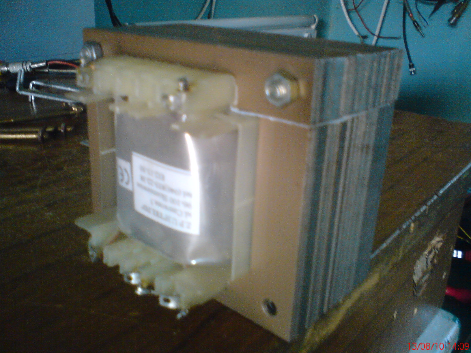
Where can I source a suitable choke, or can I use a repurposed transformer?
The showcased 8.1 H choke came from a surplus school laboratory HV supply
[Elektroda, woda400, post #8723663] You can reuse a mains transformer primary as a choke if it has an air-gap and current capacity ≥ load current; otherwise it saturates and hum rises sharply [Valve Wizard, 2019].
Which alternative preamp valves fit the same role?
Octal 6N8S, PCC88, E180F, or EF804 will work if you adjust socket, heater supply, and bias. The 6N8S offers similar gain; PCC88 provides lower noise but needs 300 mA heater current; E180F yields higher transconductance suitable for wide-bandwidth builds [Elektroda, painlust, #8720652; Siemens Data, 1971].
What performance figures can I expect beyond power?
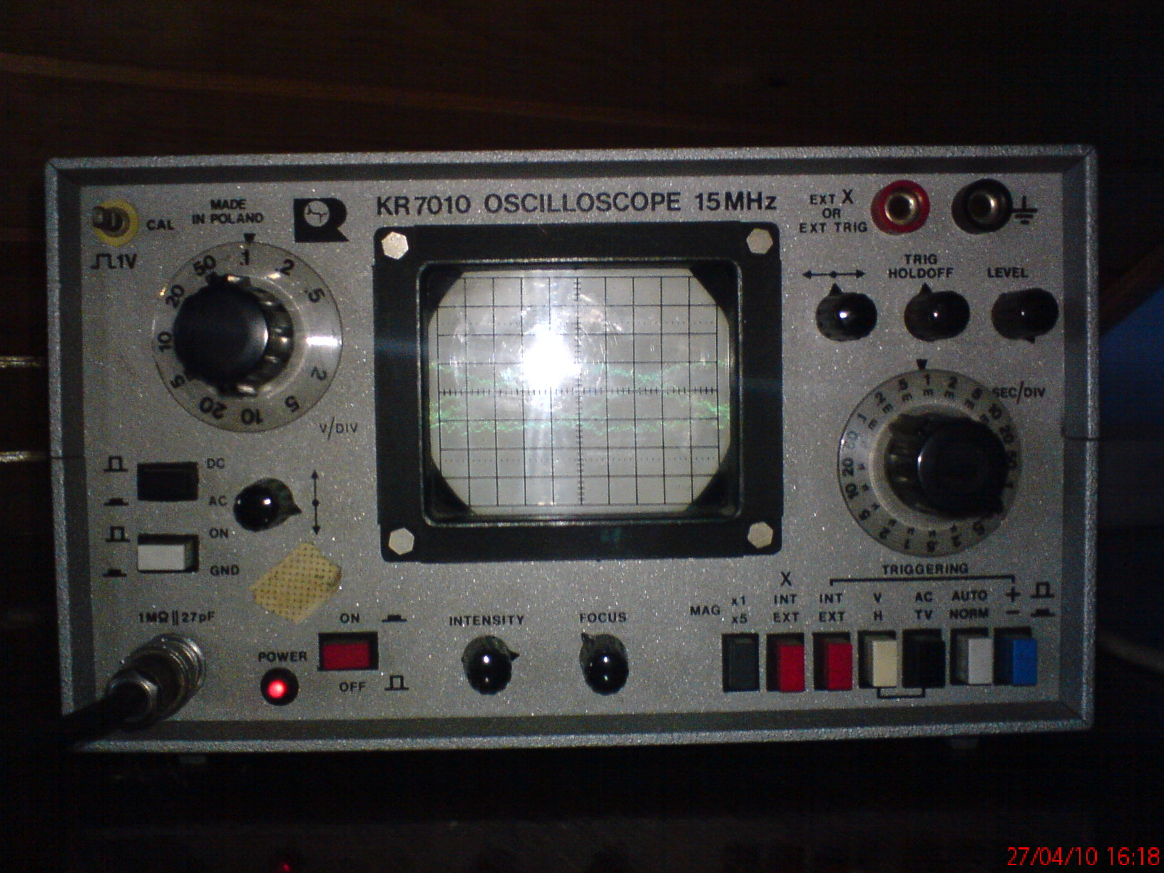
Bandwidth with standard SE output iron is typically 30 Hz–20 kHz (–3 dB) at 1 W [Lundahl LL1663 Datasheet, 2018]. Total harmonic distortion is around 2 % at 1 W in pentode and 1 % in triode. The 362 µF reservoir keeps residual ripple below 2 mV
[Elektroda, woda400, post #8720160]
What are common failure modes and how can I avoid them?
• Edge case: if the 8.1 H choke saturates (load >140 mA), ripple increases by >20 dB and the EL34 can hum audibly.
• Operating EL34 above 25 W plate dissipation causes red-plating and can destroy the tube [Mullard EL34 Data, 1962].
Set bias correctly and ensure ventilation. “Never run a glass bottle without airflow,” notes a veteran tech [AudioXpress, 2015].
How do I set the correct cathode bias on an EL34 Single-Ended stage?
- Measure cathode resistor voltage; target 28 V for ≈65 mA plate current at 245 V supply.
- Adjust resistor value: R = V/I → 28 V/0.065 A ≈ 430 Ω.
- Re-check voltage after 10 minutes warm-up; stay within ±5 %. [How-To based on Mullard EL34 Data, 1962].
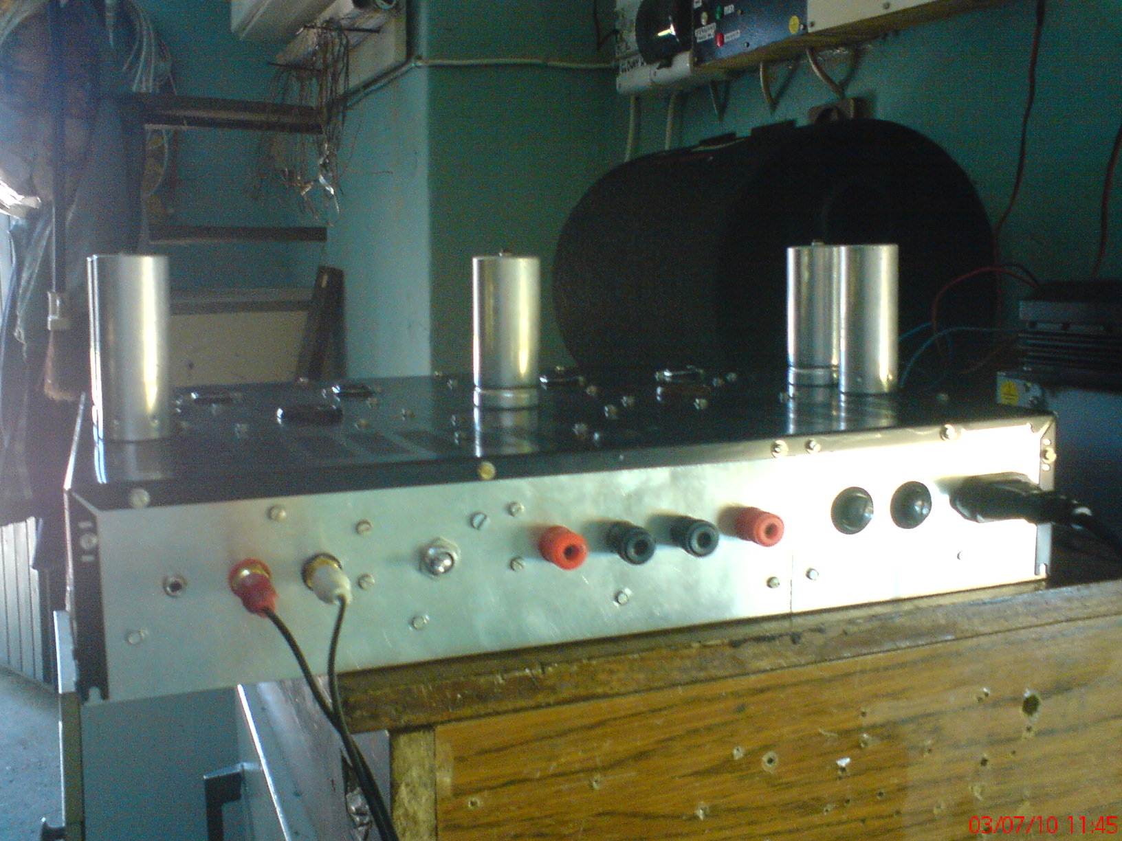
Any quick tips to improve the front-panel aesthetics?
Printing the panel artwork on photo paper, laminating it, and bonding it with double-sided tape replaces peeling stickers and delivers a factory look
[Elektroda, raczek3, post #8726765]
Generated by the language model.


Comments
And another DIY lamp looks interesting. Did you have any fun with finding the optimal weight during startup? What are the costs of its implementation? [Read more]
The gain stage is not a duplicate, but a WK with an active load. [Read more]
When it comes to looks, it's not a revelation. I would do something like this myself, but I don't have time. Why did you choose the ECC82 in this configuration? I keep wondering what to put in... [Read more]
Saying "I would do it myself, I just don't have time" reminds me a bit of the old Soviet saying at a party meeting in a factory: "we would make canned food if we had meat, but we did not have a tin."... [Read more]
Speaking of the appearance, I am not so proud of myself, but I wanted to do something on the tubes, I chose the ECC82 because I have several of them, and besides, I read that in this configuration you... [Read more]
Hello. Congratulations on the committed amplifier. What does the colleague drive with this system and in what room? Regards nitros66 [Read more]
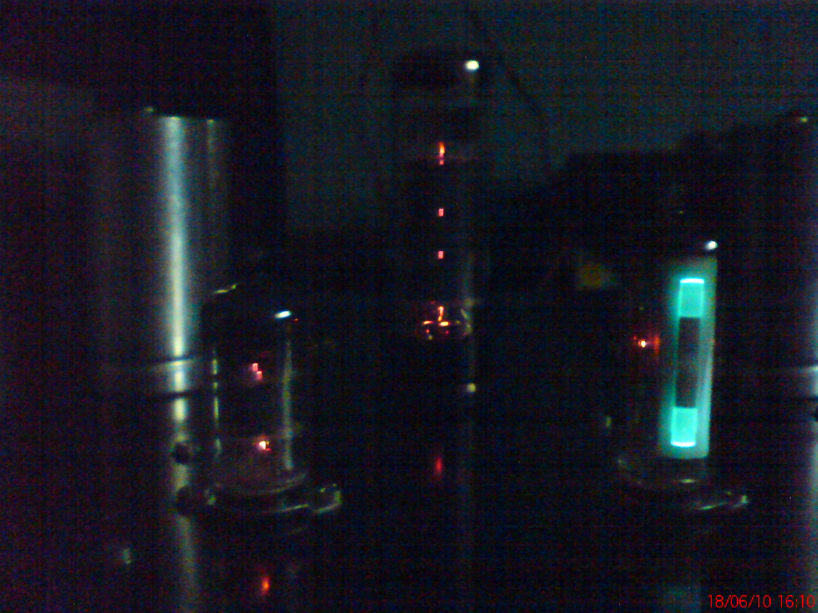
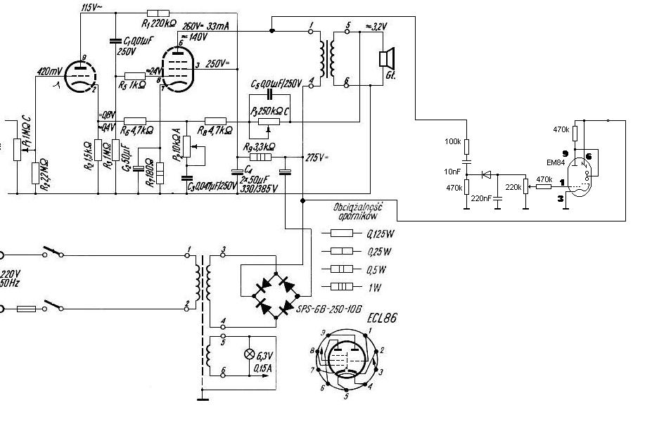
I would like to add that I do not have one EM84 lamp, as you can see in the photos, I have to buy it someday, but when you put it on the other side, it also works properly. Added after 6 [minutes]:... [Read more]
Basically ok, but you might have thought about a different layout of the elements on the carrier board - those scattered capacitors spoil the look. You could have placed them on the side of the transformer... [Read more]
Mark II admits my mistake this configuration is actually WK with active load, I confused these two configuration names. I am waiting for further opinions and questions. Regards, Woda400! Added... [Read more]
Hello I would like to know where you obtained / where did you buy a choke from the power supply (in older descriptions it was an ordinary mains transformer with the primary winding used) because apart... [Read more]
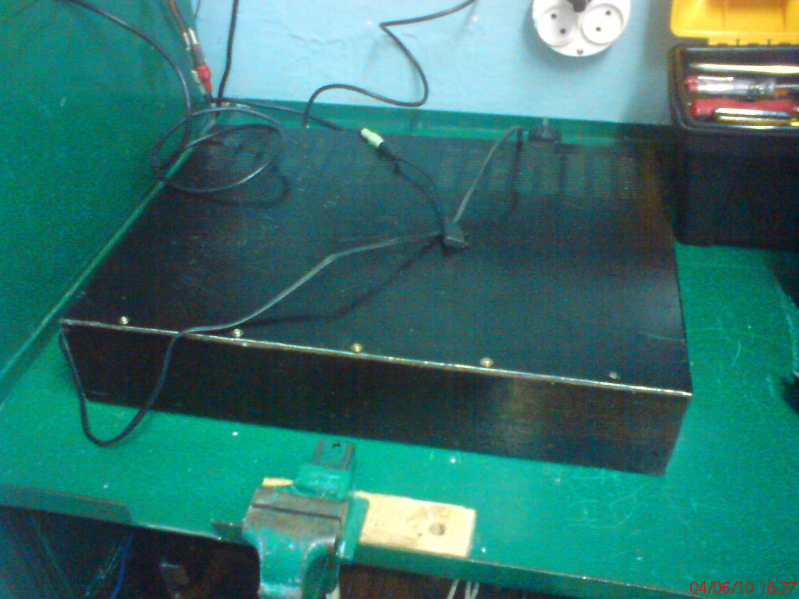
The choke comes from the school's type 2 anode power supply, here is the photo of this power supply: http://obrazki.elektroda.net/5_1289333797_thumb.jpg As for the network transformer in its... [Read more]
in my opinion, the stickers on the front panel do not fit a bit, but overall a good job ;) [Read more]
Hello, you came out with a very nice amplifier, a simple simple circuit (in my opinion the best, especially when it comes to tube designs), instead of stickers on the front panel, make this panel on your... [Read more]
I know that the stickers came out lame and in addition they came off, so I peeled them off and I'll think something about it. Yes, you are right, the equalizer is Unitra FS 032, age-old, which fits... [Read more]
The amplifier is almost nice, but it almost makes a big difference. Can anyone answer the question why almost all tube amplifiers are mounted on a "spider" and almost always unsightly? [Read more]
And where do you see the "spider" mount here? This is a traditional spatial assembly on connectors, next to turrets, the best way to build lamp devices. [Read more]
You know, this is only my first larger project, you have to learn everything one by one to get to the practice. Only then can something look like a factory product. I'll try more for the future, but... [Read more]