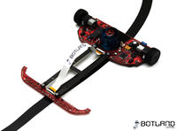
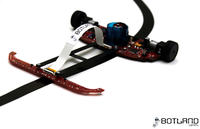
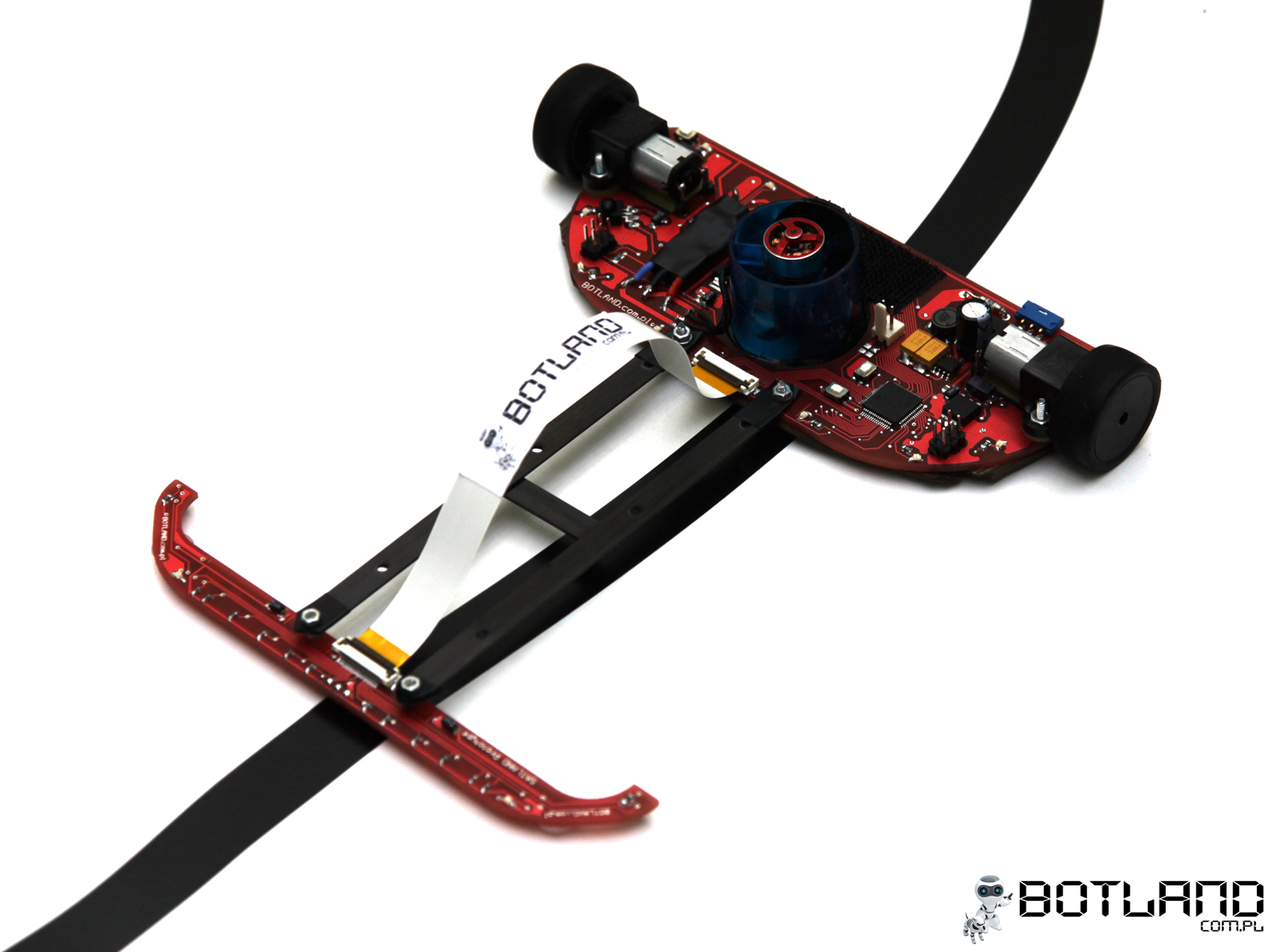
Introducing the Line Follower class robot named Impact. This is an improved version of
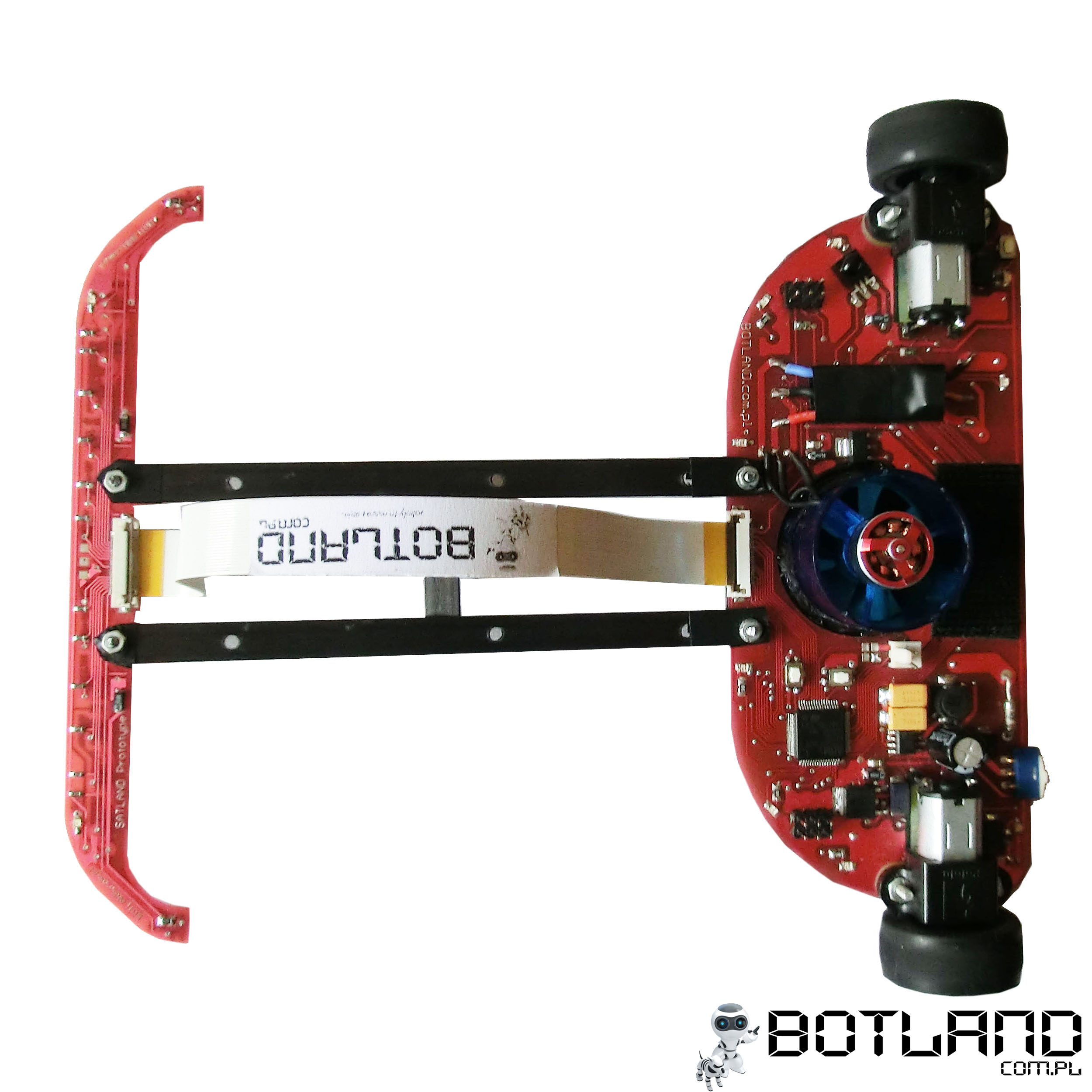
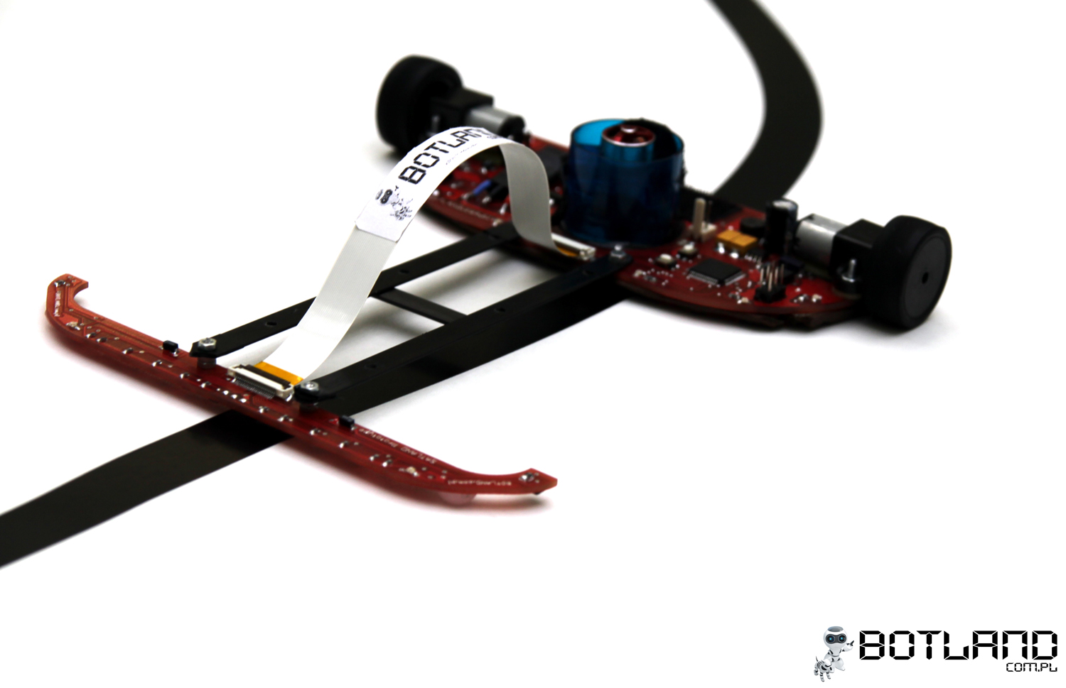
previous design described in the largest forum of Polish amateur robotics. The robot was created in 2011, until now he was the winner of all competitions in which he participated. The biggest success is undoubtedly the first place in the international robot tournament in Vienna, called by many unofficial European championships. The robot consists of two modules: the main board and the sensor plates, connected to each other by means of light carbon strips. The weight of the whole with a battery is 105 g.
Sensor module
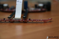
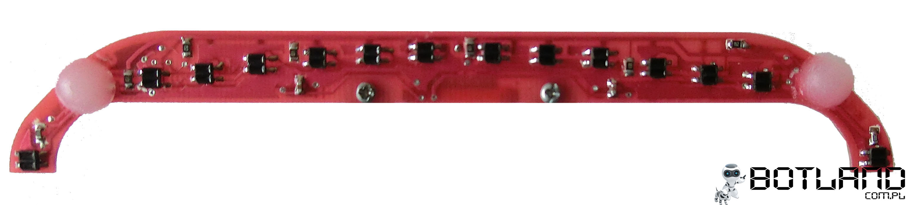
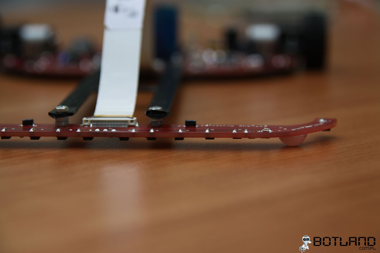
This is the element furthest from the center of rotation. The moment of inertia is large (mass multiplied by the square of the distance from the center of rotation), therefore, in order to be able to extend the sensors far, the mass of the plate should be as small as possible. In the previous version, we used 19 sensors, 16 of them in arc, 4 forward and back respectively. The plate also contained comparators and a potentiometer for setting the threshold value (Figure 1).
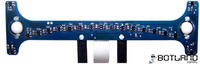 Fig. 1 Sensor system in the previous design.
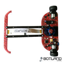
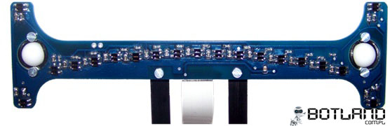
In the new module, we used 14 sensors, placed at greater distances from each other. As a result, the span of extreme sensors remained unchanged. Sensors moved forward are eliminated. It turned out that at high speeds, taking into account the inertia of the drive, the robot was unable to react effectively to the signal from them. Due to the reduction of the number of sensors, there was the possibility of using the analog-to-digital converter built into the microcontroller (16 multiplexed inputs), which allowed to dispense with the comparators. Without these additional systems, the plate sizes have been reduced. We also changed the thickness of the 1.5 mm laminate by 0.8 mm. These treatments led to a two-fold reduction in the mass of the plate from 8 to 4g. The appearance of the module is shown in Figure 2.
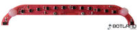 Fig.2 View of the sensor board in the current, new version of the robot.
Reflecting transducers have been used to detect lines.
KTIR0711S . Connected in groups: three sensors in series with a resistor. Pads for the digital distance sensor have been placed on the board
Sharp 40cm < br />.
Main module
The board is both a printed circuit and a construction chassis. In addition to electronic circuits, we have included propulsion engines and a tunnel drive. We managed to significantly reduce the module in relation to the previous version of the robot. The dimensions are: 140 mm x 60mm.
Electronics
The heart of the robot is a microcontroller from the native STM32. The motors are controlled by H TB6612 bridges. The power feed consists of a 5V impulse converter and a 3.3V linear stabilizer.
Microcontroller - 32-bit
STM32F103RBT6 with the ARM Cortex-M3 core, including among others : 128kB Flash, 20kB RAM, USB, CAN, UART, I2C, SPI, ADC, DAC in the LQFP64 housing, fulfills the following tasks:
readout of input port states,
converting analog signal into digital form,
generating PWM signal,
control bridges H – generating appropriate signals,
implementation of the control algorithm,
communication with the LCD module,
control of LED diodes. [/ list: u: b4e32f31d6]
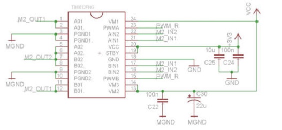
Motor controllers - two two-channel Toshiba H bridges
TB6612 , enabling:
speed control by means of PWM signal,
changing the direction of rotation of the motor by changing the states of two pins,
fast braking. [/ list: u: b4e32f31d6]
To protect against system damage at maximum current consumption by motors (1600mA), bridges A and B were connected (current efficiency increased to 2A). The bridges have been connected as shown in Figure 3.
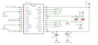 Fig. 3 Motor controller connection diagram.
Remote control
Fig. 3 Motor controller connection diagram.
Remote control
Due to the high speeds achieved during the journey, it becomes more difficult to stop the robot manually. Starting and stopping is done wirelessly, using infrared. The ATtiny13 system used is responsible for decoding the signal from the remote control, which transmits the signal in the RC5 standard. The solution developed by Philips increases the resistance to interference from the environment and creates the possibility of using universal and publicly available remotes. Another advantage is the ease of using additional buttons on the remote control. An additional processor has been used due to the high requirements for the reliability of remote stopping operations, e.g. in emergency situations.
Drive
The drive consists of two engines
Pololu HP with transmission
10: 1 with the following technical parameters:
Idle speed at 6V: 3000rpm,
Idle speed (6V): 120mA,
Peak current: 1600mA,
Torque: 0.3 kg * cm (29 mNm),
Dimensions: 24 x 10 x 12 mm,
Weight: 10g. [/ List: u: b4e32f31d6]
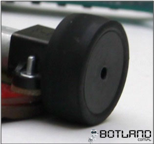
The wheels consist of rims made of plastic polyamide and specially selected tires. The rim fits tightly on the motor shaft and protected with cyanoacrylate adhesive (Figure 4)
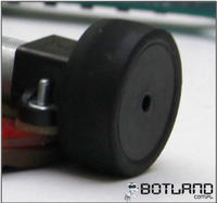 Fig. 4 Wheels made of polyamide with Mini-Z tires.
Different types of tires have been tested. The best choice turned out to be the tires used in the Mini-Z car models. These are 12mm wide and 3mm thick tires. The next parameter is the hardness, which is 20 ° (on a scale of 10 ° -60 °). Tires with lower hardness are characterized by greater adhesion, but they wear out more quickly. The diameter of the rim with the tire is 27mm. The cleanliness of the tires is also very important. Before each passing, they are cleaned to remove dust particles that cause loss of adhesion and have a negative effect on performance.
Theoretical maximum linear speed of the robot in the limit of 3m / s. Depending on the route, the average speed achieved is 2.3-2.5 m / s.
Tunnel drive
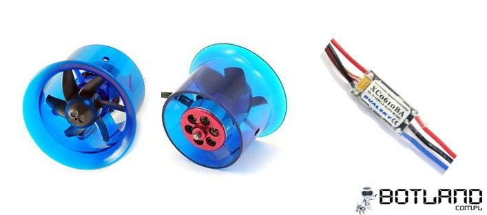
An important element is the EDF tunnel drive. It is a turbine, as it is used in flying models, but mounted inversely. The element is to create an additional pressure force, which helps the robot to stay on the route in curves at high speeds (above 2m / s). The turbine is equipped with a brushless motor (11,000 rpm, power consumption about 4A), which is controlled by the company's controller
Dualsky .
 Fig. 5 Tunnel drive EDF27 with engine control.
Power supply
Fig. 5 Tunnel drive EDF27 with engine control.
Power supply
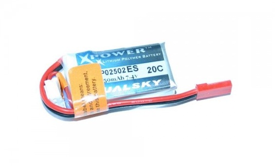
To power the robot the package was used
Lithium-Polymer Dualsky 220mAh 25C 7.4V (Figure 6). The continuous current that the package is able to provide is 5.5A, while the peak current is 11A, it is sufficient for proper power supply. The battery allows for approx. 30 seconds of optimal driving, after which the supply voltage drops which negatively affects the dynamics and maximum speed of the robot. During the competition, battery replacement is usually performed every 2 rides, which allows the use of full engine power. The mass, which is about 16 grams, had a big impact on the use of such a small package.
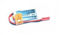 Fig. 6 Dualsky battery 220mAh used.
Directly from the battery are powered by motors and a tunnel drive. Electronic components that require 5V voltage are supplied with stabilized voltage using an adjustable converter.
ST1S10PHR with current efficiency up to 3A. The processor's power, or 3.3V, comes from a linear LDO (low-dropout) system.
LF33CT , whose input voltage is derived from the 5V converter. The power scheme is shown in Figure 7.
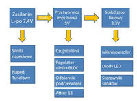 Fig. 7 Block diagram of the power path.
User interface
Fig. 7 Block diagram of the power path.
User interface
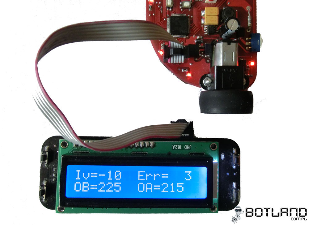
Setting up the regulator requires frequent changes of parameters such as maximum speed of driving motors, turbine rotor speed or PID controller gain. Connecting the robot to the computer after each pass, especially at competitions where the service stations are located at certain distances from the route was very troublesome. A module was created with an LCD display for viewing the settings and buttons for adjusting them. As mentioned earlier, mass is a key parameter, therefore the system is a separate module that connects to the robot via the UART interface.
The main functions of the module are:
choice of regulator's settings,
choosing the maximum speed,
selection of rotational speed of the tunnel rotor turbine rotor,
checking the correct operation of the sensors,
viewing the output data of the PID controller,
setting the threshold voltage value for the reflective sensors. [/ list: u: b4e32f31d6]
 Fig. 8. Module with LCD display.
Software
Fig. 8. Module with LCD display.
Software
The software was written in C language using the libraries provided by STM: STM32F10x_StdPeriph_Lib_V3.5.0. The control algorithm is PID with some modifications.
Achievements so far:
1st place T-BOT – Wałbrzych - 2012
1st place Robomaticon – Warsaw - 2012
1. the place of the Robot Challenge – Vienna - 2012
1st place of the Tri-City Robot Tournament - Gdańsk - 2012
1st place CybAirBot - Poznań - 2012
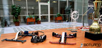
Photos konstrukcji
 Filmy z zawodów
Autorzy konstrukcji:
Bartosz Derkacz
Szymon Mońka


Comments
So this year belongs to you - Congratulations! :) 1. How did you choose the distance between the sensors and the wheel axis (center of rotation)? Experimentally, or specific calculations? 2.... [Read more]
Hello, great design, congratulations on achievements ;) I would like to note that the first two drawings were inversely placed (those with the sensor module). I have a question about the infrared... [Read more]
Congratulations, fantastic robot. Can you know how much it costs to make such a gem? [Read more]
We selected experimentally. This distance is especially important if straight angles are on the route. The faster they are detected, the robot will more accurately overcome this problem and will lose less... [Read more]
making the collars on the "main" module, which look a bit like those in hovercraft, would cause the robot to suck up to the track, of course it would result in a significant increase in grip. [Read more]
The flanges are made of window seals. However, there is a problem: on uneven tracks and plate connections, the robot may hang, so they can not be too long. [Read more]
This is only half of the restrictions, because the opposite (I think) overcoming narrow routes with too long "nose" + moment of inertia, which you paid particular attention to. Will you change this... [Read more]
You're right, for a narrow and winding route, a shorter nose is a better solution. We have several sets of slats of different lengths and we change before the competition. The holes are leftovers after... [Read more]
And a question related to this but more about the practice of participation in such events: Do you do this selection before the start, seeing the route, or after passing a specific route in the test run? In... [Read more]
We choose the length before the start of the competition, although it was also possible to make a correction during testing. As a rule, routes in Poland are similar (gentle arches, long straights and... [Read more]
Hello, I think so, because the discussion here shows that in the competitions you can make a trial run, did not the authors think about "remembering the route" and in the second pass use this information... [Read more]
I have a question: what is the name of this ribbon connecting the main PCB with the sensors. Where can you buy something like that? What are the prices? I have one with the pins removed. [Read more]
We plan to remember the route in the next construction. The tape is a ffc / fpc connector, 0.5 mm pitch, available in e.g. TME [Read more]
I found, you can buy it for less than PLN 5? I did not know that it is so expensive; / [Read more]
I warmly welcome. So out of pure curiosity, I would like to ask how the rules of such professions usually apply to, for example, the use of a turbine which increases the pressure and the general method... [Read more]
The meaning of these professions will lose. The point of this competition is to build a robot that will negotiate a route it does not know and will do it well and quickly. Currently, these competitions... [Read more]
An interesting proposition, I met her for the first time. However, I do not know if this would help in the development of competition. It must be remembered that such robotic professions are intended to... [Read more]
Of course, you should not limit it. I'm talking about it to make competition more ... ... exciting. Of course, you are right. I encourage my kids by showing an easy way to build. And then I raise... [Read more]
I have traveled around 10 times a year for such competitions and so far (at least in LFs) I have not met with typical computer science. They are always people interested in electronics. Everyone is trying... [Read more]