1. Objective of the device I drive now with Mazda 6 from 2003. with a regular audio system (not Bose). Unfortunately, there is no possibility to connect an external source of Aux sound, eg a smartphone. I decided to make this an option, and to not have to tangle with the cables, everything was supposed to work via Bluetooth.
2. Description of the solution
In short, the solution is to use an unused button that activates the tape recorder (TAPE / MD). After switching to TAPE / MD, the sound from the system described below is fed into the loudspeakers. Here is the difficulty, because you should cheat the system so that he would think that the cassette player is present. The MazdaSpoof project comes handy from the
website http://nikaosapi.org/w/index.php/MazdaSpoof_-_A_Tape_Deck_Emulator . A very simple system on ATtiny45 communicates on the data bus with the audio system presenting itself as a cassette player. The whole should be able to apply to other Mazda models from that period, Nikosapi speaks of Mazda 3 and Protege.
The complete solution is basically the integration of ready-made elements. As a bluetooth audio module I used a cheap bluetooth aux adapter, powered from a USB socket, purchased on a well-known auction site. I only got rid of the plastic housing to make it easier to fit into the printed circuit board. The system is powered + 12V, so it was necessary to provide a voltage reduction to 5V. Using an ordinary linear stabilizer would require almost 1W of power dissipation, but I just had the step-down converter board on the LM2596 used with Arduino at hand. Just for this purpose and the cost below 5 PLN.
Scheme:
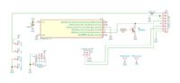
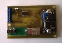
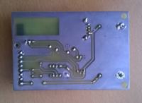
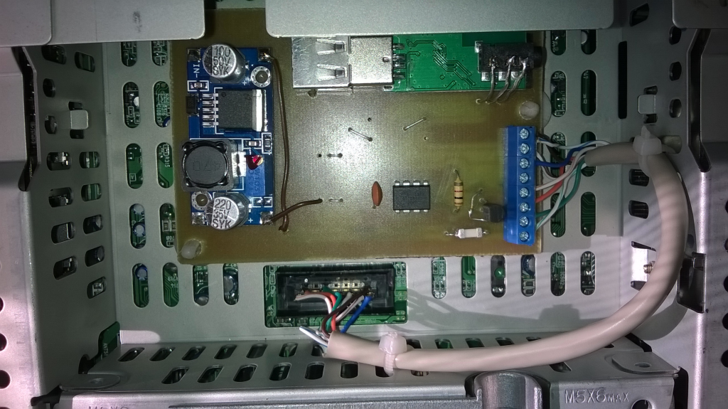
The system is integrated on one printed circuit board designed in KiCad. The plate visible in the pictures is still in the initial version, with errors and then removed places for potentiometers. I programmed the ATtines before soldering the usbasp programmer. I downloaded the ready feed from the MazdaSpoof website, here I attach a copy.
Make sure that the fuse bits are set to the default values for this controller, i.e. CKSEL = "0010", SUT = "10", CKDIV8 = programmed. This gives the clock source settings on the internal RC 8MHz with a pre-dialer of 1: 8. Before soldering the inverter it is important to set the voltage to 5V so as not to destroy the microcontroller. It does not hurt to drip nail polish on the potentiometer screw, due to the vibrations in the car. At the end you need to attach the adapter to the USB socket and solder the audio leads. So that the adapter does not move, I used a car double-sided tape.
 spoof.h...zip (2.01 kB)You must be logged in to download this attachment. mazda_spoo..._kicad.zip (13.76 kB)You must be logged in to download this attachment.
3. Installation in the car After soldering the system and test on the desk, I started the final assembly. The entire center console module must be removed for this purpose. It is not too difficult. After removing the cover around the shift stick, two screws are shown holding the console from the bottom. The third screw is on the right side at the top. Access to it is after taking out the passenger compartment drawer. After unscrewing the screws, it is not enough to pull the console from the bottom to let the whole go. It remains to disconnect the wires, cubes and we have the console removed. There are videos on youtube showing this in detail so I do not paste photos of this stage.
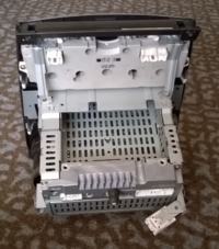
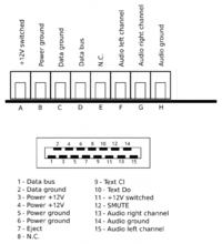
And here is the console after removal, you can see the cassette player bay. There is a connector to connect our plate to. Unfortunately, I could not match the cube that would fit in here and I was forced to solder the wires straight to the connector. The wiring diagram for connection is as follows (NC, of course, not combined):

The plate is fixed with computer pins and fixed with double-sided tape. After putting the console back in place, it is worth checking if the whole works, and for example the radio, so as not to spin everything again.
4. Use of The service is very simple:
- we pair our device with the adapter, the name and password detected depend on the specific adapter model. With high probability the password is 1111.
- we connect the device
- we press TAPE / MD in the car and enjoy the sound
So far, everything works without problems. The quality of sound does not fall on your knees, but at the level of mute in Mazda, it does not matter. I set up the device after the summer heat, so I do not know what effect the high temperatures will have, but I will soon see the influence of low temperatures. The budget of the parts was about PLN 50-60


Comments
Congratulations on a nicely made device that extends the functions of the car. I would have a question about the bluetooth module, how much did it cost? Do you have any housing photos? I would like to... [Read more]
Does your bluetooth module report a Paired message every now and then as you do not play any music? [Read more]
In the evening I will throw the picture of the case. As for coverage, I only checked if it works in a car. I was a bit worried if the metal components of the console would not screen. I did not hear "paired"... [Read more]
A very interesting device. Buddy, could you give a picture of your radio and some symbol? Brother has a similar system in premacy, maybe it would give advice and make some extra money for him. [Read more]
As for the bluetooth modules - I had a bit of a deal with them and I must say that they cut off the bass very much. It helps desoldering capacitors on the board, on the other hand, the jack connectors.... [Read more]
to do with them And would you be able to specify on which chip they are made? [Read more]
Indeed, in my own the basses were bad, maybe it can be conquered here by removing the capacitors. I just bought a completely blind adapter based on RDA5851SX, here the photo identical to Amazon, where... [Read more]
I have a question how big and how soldered because I have the same module and very good sound quality compared to the cable [Read more]
Unfortunately, all the modules that I had, already came out in the devices - went into the "world" :) . If you look closely, you can see where the guides from the jack are located on the other side,... [Read more]
There is also an easier way to listen to your music in the mazda without carrying a ton of CDs - only more expensive. Just on the radio, solder one jumper (you can search for the video on youtube - shown... [Read more]
But Bluetooth in this device is just a selection of a Phaeton colleague. There is usually an audio input and you can connect what you want. [Read more]
Hello. And would the inclusion of such a "cheat module" be applied instead of the Mazda changer ?? I have a cassette in Premacy and I would like to replace the cd / aux changer with an ordinary line input... [Read more]
Under cd / aux you will not connect because these aux is not a line input, you must combine with "Tape". [Read more]
And the input from the changer does not introduce an analog signal but a digital one that just processes the radio ?? And these mp3 changers emulators give a radio receiver also a digital signal ?? [Read more]
Probably the output of the changer provides an analog signal but the radio communicates with the changer by means of some bus, it is possible that CAN and if the radio does not detect the changer it will... [Read more]
Can you use a circuit without a BT module and the jack / jack alone? [Read more]
Hello. I've been trying to start the system for some time. I used aTiny85 (in the digispark system) programmed with the spoof.hex feed. https://obrazki.elektroda.pl/6134995400_1532264469_thumb.jpeg... [Read more]
I do not see any obstacles. Added after 6 [minutes]: Without the transistor as in my schematic, the microcontroller can receive data, but it can not send an answer, so there is no chance that... [Read more]
Thanks for the answer. Yes, I have. Transistor 2N3904, in the ADC2 system -> collector-> data bus, ADC3-> resistor-> base, emitter-> mass. Should it amplify the signal from the controller? I'm... [Read more]