logo elektroda
logo elektroda
X
logo elektroda

Bluetooth audio in the Mazda 6 2003 car

Phaeton 38865 27
ADVERTISEMENT
Treść została przetłumaczona polish » english Zobacz oryginalną wersję tematu
  • 1. Objective of the device
    I drive now with Mazda 6 from 2003. with a regular audio system (not Bose). Unfortunately, there is no possibility to connect an external source of Aux sound, eg a smartphone. I decided to make this an option, and to not have to tangle with the cables, everything was supposed to work via Bluetooth.

    2. Description of the
    solution
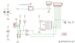
    In short, the solution is to use an unused button that activates the tape recorder (TAPE / MD). After switching to TAPE / MD, the sound from the system described below is fed into the loudspeakers. Here is the difficulty, because you should cheat the system so that he would think that the cassette player is present. The MazdaSpoof project comes handy from the website http://nikaosapi.org/w/index.php/MazdaSpoof_-_A_Tape_Deck_Emulator . A very simple system on ATtiny45 communicates on the data bus with the audio system presenting itself as a cassette player. The whole should be able to apply to other Mazda models from that period, Nikosapi speaks of Mazda 3 and Protege.

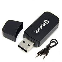
    The complete solution is basically the integration of ready-made elements. As a bluetooth audio module I used a cheap bluetooth aux adapter, powered from a USB socket, purchased on a well-known auction site. I only got rid of the plastic housing to make it easier to fit into the printed circuit board. The system is powered + 12V, so it was necessary to provide a voltage reduction to 5V. Using an ordinary linear stabilizer would require almost 1W of power dissipation, but I just had the step-down converter board on the LM2596 used with Arduino at hand. Just for this purpose and the cost below 5 PLN.
    Scheme:
    Bluetooth audio in the Mazda 6 2003 car

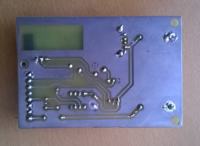
    The system is integrated on one printed circuit board designed in KiCad. The plate visible in the pictures is still in the initial version, with errors and then removed places for potentiometers. I programmed the ATtines before soldering the usbasp programmer. I downloaded the ready feed from the MazdaSpoof website, here I attach a copy.
    Make sure that the fuse bits are set to the default values for this controller, i.e. CKSEL = "0010", SUT = "10", CKDIV8 = programmed. This gives the clock source settings on the internal RC 8MHz with a pre-dialer of 1: 8. Before soldering the inverter it is important to set the voltage to 5V so as not to destroy the microcontroller. It does not hurt to drip nail polish on the potentiometer screw, due to the vibrations in the car. At the end you need to attach the adapter to the USB socket and solder the audio leads. So that the adapter does not move, I used a car double-sided tape.
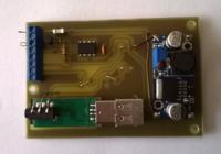
    Bluetooth audio in the Mazda 6 2003 car Bluetooth audio in the Mazda 6 2003 car spoof.h...zip Download (2.01 kB) mazda_spoo..._kicad.zip Download (13.76 kB)

    3. Installation in the car

    After soldering the system and test on the desk, I started the final assembly. The entire center console module must be removed for this purpose. It is not too difficult. After removing the cover around the shift stick, two screws are shown holding the console from the bottom. The third screw is on the right side at the top. Access to it is after taking out the passenger compartment drawer. After unscrewing the screws, it is not enough to pull the console from the bottom to let the whole go. It remains to disconnect the wires, cubes and we have the console removed. There are videos on youtube showing this in detail so I do not paste photos of this stage.
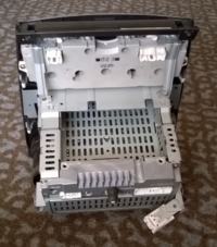
    Bluetooth audio in the Mazda 6 2003 car
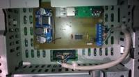
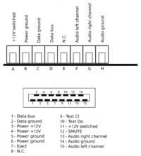
    And here is the console after removal, you can see the cassette player bay. There is a connector to connect our plate to. Unfortunately, I could not match the cube that would fit in here and I was forced to solder the wires straight to the connector. The wiring diagram for connection is as follows (NC, of course, not combined):
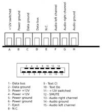
    Bluetooth audio in the Mazda 6 2003 car Bluetooth audio in the Mazda 6 2003 car
    The plate is fixed with computer pins and fixed with double-sided tape. After putting the console back in place, it is worth checking if the whole works, and for example the radio, so as not to spin everything again.

    4. Use of
    The service is very simple:
    - we pair our device with the adapter, the name and password detected depend on the specific adapter model. With high probability the password is 1111.
    - we connect the device
    - we press TAPE / MD in the car and enjoy the sound
    So far, everything works without problems. The quality of sound does not fall on your knees, but at the level of mute in Mazda, it does not matter. I set up the device after the summer heat, so I do not know what effect the high temperatures will have, but I will soon see the influence of low temperatures. The budget of the parts was about PLN 50-60

    Cool? Ranking DIY
    Do you have a problem with Arduino? Ask question. Visit our forum Arduino.
    About Author
    Phaeton
    Level 19  
    Offline 
    Phaeton wrote 408 posts with rating 155, helped 15 times. Live in city Kraków. Been with us since 2004 year.
  • ADVERTISEMENT
  • #2 16018673
    szymon122
    Level 38  
    Congratulations on a nicely made device that extends the functions of the car. I would have a question about the bluetooth module, how much did it cost? Do you have any housing photos? I would like to see if I bought identical on ebay for 1.3 $. What is the range? Do you have a photo from the elements side?
  • #3 16019051
    Duch__
    Level 31  
    Does your bluetooth module report a Paired message every now and then as you do not play any music?
  • #4 16019154
    Phaeton
    Level 19  
    In the evening I will throw the picture of the case. As for coverage, I only checked if it works in a car. I was a bit worried if the metal components of the console would not screen. I did not hear "paired" messages, only "connected" / "disconnected" when connecting / disconnecting.
  • ADVERTISEMENT
  • #5 16019460
    pier
    Level 24  
    A very interesting device.
    Buddy, could you give a picture of your radio and some symbol?
    Brother has a similar system in premacy, maybe it would give advice and make some extra money for him.
  • ADVERTISEMENT
  • #6 16019926
    wojtek0995
    Level 27  
    As for the bluetooth modules - I had a bit of a deal with them and I must say that they cut off the bass very much. It helps desoldering capacitors on the board, on the other hand, the jack connectors.
    Personally, I will not recommend the cheapest modules because they sow mercilessly, it is better to spend a bit more and look for their counterparts on the foreign "allegro".
    The project itself - interesting. Good integration with the car, it counts
    :)
    .
  • #7 16019985
    szymon122
    Level 38  
    wojtek0995 wrote:
    What about bluetooth modules - I had
    to do with them
    And would you be able to specify on which chip they are made?
  • ADVERTISEMENT
  • #8 16020051
    Phaeton
    Level 19  
    Indeed, in my own the basses were bad, maybe it can be conquered here by removing the capacitors. I just bought a completely blind adapter based on RDA5851SX, here the photo identical to Amazon, where they want $ 13 for it, I bought with us for 30 PLN without shipment:
    Bluetooth audio in the Mazda 6 2003 car

    pier wrote:
    could you give a photo of your radio and some symbol?

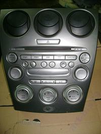
    Unfortunately I do not have the symbol, but the console itself looks like in every mazda 6, eg here (just not my picture):
    Bluetooth audio in the Mazda 6 2003 car
    Nevertheless, from what I read a lot of Mazd from those years has differently looking radios but with common electronics, I suspect that if the same 15-pin connector is the system will work.
    szymon122 wrote:
    What is the range?

    Out of curiosity I checked and works to some 5m from the car with the door closed. Then the sound begins to rip.
  • #9 16020376
    alucard333
    Level 10  
    wojtek0995 wrote:
    As for the bluetooth modules - I had a bit of a deal with them and I must say that they cut off the bass very much. It helps desoldering capacitors on the board, on the other hand, the jack connectors.
    Personally, I will not recommend the cheapest modules because they sow mercilessly, it is better to spend a bit more and look for their counterparts on the foreign "allegro".
    The project itself - interesting. Good integration with the car, it counts
    :)
    .

    I have a question how big and how soldered because I have the same module and very good sound quality compared to the cable
  • #10 16020419
    wojtek0995
    Level 27  
    Unfortunately, all the modules that I had, already came out in the devices - went into the "world"
    :)
    .
    If you look closely, you can see where the guides from the jack are located on the other side, on the other side there are these capacitors. It seems to me that they were the size of 2012.
  • #11 16021201
    thomas-cs
    Level 14  
    There is also an easier way to listen to your music in the mazda without carrying a ton of CDs - only more expensive. Just on the radio, solder one jumper (you can search for the video on youtube - shown step by step). You can then connect a changer emulator, eg Yatour. The sound quality is much better than by bluetooth, thanks to the memory card you can keep more music, and does not discharge the battery in your phone
    :)
  • #12 16021547
    pier
    Level 24  
    But Bluetooth in this device is just a selection of a Phaeton colleague. There is usually an audio input and you can connect what you want.
  • #13 16021886
    aftys6
    Level 19  
    Hello. And would the inclusion of such a "cheat module" be applied instead of the Mazda changer ?? I have a cassette in Premacy and I would like to replace the cd / aux changer with an ordinary line input for connecting mp3 or navigation.
  • #14 16022294
    daro19862
    Level 25  
    Under cd / aux you will not connect because these aux is not a line input, you must combine with "Tape".
  • #15 16022505
    aftys6
    Level 19  
    daro19862 wrote:
    Under cd / aux you will not connect because these aux is not a line input, you must combine with "Tape".

    And the input from the changer does not introduce an analog signal but a digital one that just processes the radio ??
    And these mp3 changers emulators give a radio receiver also a digital signal ??
  • #16 16023136
    daro19862
    Level 25  
    Probably the output of the changer provides an analog signal but the radio communicates with the changer by means of some bus, it is possible that CAN and if the radio does not detect the changer it will not switch the signal to AUX.
  • #17 17322886
    kacper123321
    Level 2  
    Can you use a circuit without a BT module and the jack / jack alone?
  • #18 17343459
    maliniak1969
    Level 10  
    Hello.

    I've been trying to start the system for some time. I used aTiny85 (in the digispark system) programmed with the spoof.hex feed.

    Bluetooth audio in the Mazda 6 2003 car

    I cut resistors R1 and R2.
    I have connected everything as in the descriptions, that is:

    Bluetooth audio in the Mazda 6 2003 car

    A-> 11
    B-> 6
    C-> 2
    D> 1
    FGH-> jack audio

    Unfortunately, the only effect is blocking the CD button and playing the tile.
    Does anyone have any idea what might be wrong?

    greetings
    :)
  • #19 17344023
    Phaeton
    Level 19  
    kacper123321 wrote:
    Can be used without BT module and the jack / jack alone?

    I do not see any obstacles.

    Added after 6 [minutes]:

    maliniak1969 wrote:
    Hello.
    Does anyone have any idea what might be wrong?

    Without the transistor as in my schematic, the microcontroller can receive data, but it can not send an answer, so there is no chance that it will work. Do you have this transistor?
  • #20 17344435
    maliniak1969
    Level 10  
    Phaeton wrote:
    Without a transistor like in my schematic, the microcontroller can receive data, but can not send an answer, so there is no chance that it will work. Do you have this transistor?


    Thanks for the answer.

    Yes, I have.
    Transistor 2N3904, in the ADC2 system -> collector-> data bus, ADC3-> resistor-> base, emitter-> mass.
    Should it amplify the signal from the controller?
    I'm not sure if I put in a good spoof.hex batch

    C: \ Users \ maliniak \ AppData \ Local \ Arduino15 \ packages \ digistump \ tools \ micronucleus \ 2.0a4 / launcher -cdigispark --timeout 60 -FLash: in: C: \ Users \ maliniak \ AppData \ Local \ Temp \ arduino_build_646572 /spoof.hex:i
    Running Digispark Uploader ...
    Plug in device now ... (will timeout in 60 seconds)
    > Please plug in the device ...
    > Press CTRL + C is the terminate the program.
    > Device is found!
    connecting: 16% complete
    connecting: 22% complete
    connecting: 28% complete
    connecting: 33% complete
    > Device has firmware version 1.11
    > Available space for user applications: 6330 bytes
    > Suggested sleep time between sending pages: 8ms
    > Whole page count: 99 page size: 64
    > Erase function sleep duration: 792ms
    parsing: 50% complete
    > Erasing the memory ...
    erasing: 55% complete
    erasing: 60% complete
    erasing: 65% complete
    > Starting to upload ...
    writing: 70% complete
    writing: 75% complete
    writing: 80% complete
    > Starting the user app ...
    running: 100% complete
    >> Micronucleus done. Thank you!

    Greetings.
  • #21 17350538
    kacper123321
    Level 2  
    As for programming the attiny system .. You can do it with the help of arduino uno, which I have. I have a request, is anyone able to prepare the batch, instructions for dealing with arduino? I will be grateful
  • #22 17351560
    Phaeton
    Level 19  
    I did not use this digispark, but I see that it uses a micronucleus bootloader. Surely this is a problem, because the bootloader first starts and only after a while the right program. It may cause that the system will not "present" on time after the power is turned on. However, I recommend programming the programmer directly, not using a bootloader. I did it with the usbasp clone and it worked right away.

    As for programming by Arduino, I have not tried, but you certainly do not have to make a special batch, you just need to properly connect the legs of the attiny to arduino and load the program to the ISP. I have seen the instructions on various pages but rather the tutorial will not do it here.
  • #23 17351732
    maliniak1969
    Level 10  
    Phaeton wrote:
    I did not use this digispark, but I see that it uses a micronucleus bootloader. Surely this is a problem, because the bootloader first starts and only after a while the right program. It may cause that the system will not "present" on time after the power is turned on. However, I recommend programming the programmer directly, not using a bootloader. I did it with the usbasp clone and it worked right away.

    As for programming by Arduino, I have not tried, but you certainly do not have to make a special batch, you just need to properly connect the legs of the attiny to arduino and load the program to the ISP. I have seen the instructions on various pages but rather the tutorial will not do it here.


    Thanks to Phaeton. As you wrote, I programmed another layout without a bootloader with a usbasp clone and it went straight away. I finally have TAPE PLAY on the display after pressing TAPE / MD. Regarding my problem, I found the answer here:

    Quote:
    "The fuse settings of lfuse 0x62 hfuse 0xDF efuse 0xFF are the factory default settings for the attiny85 MCUs. It sets it up the default clock is the 8Mhz internal clock, with prescaling of 8, making the system clock speed 1Mhz. No low voltage (brownout) detection, does not allow the Attiki to reprogram itself, and leaves the external reset enabled.

    The settings that the digispark uses (lfuse 0xE1 hfuse 0x5D efuse 0xFE) rather instructs the Attiny85 to use the PLL clock (nominally 16Mhz) with no default prescaling (so it really will be 16Mhz system clock). The brown-out detection is turned on (as recommended when using the PLL) and set to trigger at approximately 2.7v. The external reset is disabled (I use the reset pin as an I / O). And self-programming is enabled.

    The brown-out detector prevents the Attiny85 from recharging until the voltage rises sufficiently. Self-programming is the same as the micronucleus 'bootloader' is able to reprogram the Attiny85, and even update itself. "


    I did not take this into account though you wrote to check the coffee grounds. Thanks again for your interest and help. Greetings.
  • #24 17353441
    kacper123321
    Level 2  
    How to program, I have already come. Only the system fulfills a function, and what should you enter so that it can do it? Is anyone able to prepare code for arduino IDE? I would be grateful.
  • #25 17355239
    herPitek
    Level 12  
    From myself in the topic of bluetooth in the car I can add that cheap modules have very poor sound quality. Poor frequency response, whistling and noise during playback. However, I found good equipment at our Far East friends Sanwu Audio . Bluetooth 4.2, aptx support, great sound quality. No built-in batteries, no buttons for pairing, just plug in 5V power via a micro usb and automatically pair with the phone. For the car or amplifier in the house perfect.
  • #26 17422122
    demolek
    Level 11  
    What program can you load this feed into attiny45 via the usbasp programmer?
  • #27 17422580
    Phaeton
    Level 19  
    demolek wrote:
    What program can you load this feed into attiny45 via the usbasp programmer?

    One of them is AVRdude.
  • #28 19143907
    Greenlax
    Level 1  
    Hello I've got this weird issue with powering the Tape Deck Emulator. I've wired up everything and used same components as tutorial above. Problem is with Mazda Entertainment System Connector. If I connect pin A (+12 switched input) to pin 11 (+12 switched output) it does not work because the voltage on that pin is 3.3V, however if I measure voltage on that pin with pin A (Tape Deck Emulator ) unconnected, the voltage is 12V. If I connect pin A to pin 3 or 4 (constant 12V) it works without a problem but it discharges battery all the time. Did anyone have a similiar problem or knows where the problem might be ? Please let me know. I have Mazda 3 2004.

Topic summary

The discussion revolves around integrating Bluetooth audio capabilities into a 2003 Mazda 6 with a standard audio system. Users explore the use of a tape deck emulator, specifically the MazdaSpoof project, which allows the car's audio system to recognize a Bluetooth module as a cassette player. Key challenges include ensuring the system is tricked into thinking a cassette player is present and addressing sound quality issues, particularly bass response. Various Bluetooth modules are discussed, with recommendations against cheaper options due to poor sound quality. Users share experiences with different components, including the ATtiny microcontroller and specific Bluetooth modules like the RDA5851SX and Sanwu Audio. The conversation also touches on alternative solutions, such as using a CD changer emulator for better sound quality.
Summary generated by the language model.
ADVERTISEMENT