I decided to write here on the forum about my exploits. Maybe someone would need such power. Note: I do not take responsibility if something happens to you, the reader, while playing with used power adapters that I am writing about here. A week ago I found a 600W power supply from a good Delta company on Allegro:
DPS-600QB for only PLN 49. I bought 2 pieces right away. The power supply at the output allows to "pull" up to 40A from the 12V line and up to 28A from the 5.1V line. The strange 16-pin terminal discouraged me from buying, but I decided to get to these pins, which in a moment. After short tests, it turned out that the 12V and 5.1V lines give the output 11.9V and 5.10V respectively. The power supply is for real
very loud , I do not advise spending several hours in its vicinity.
I dismantled the whole thing and started to investigate what the pins from the 4x4 pin are for. Without going into details, I have determined that the pinout looks like this:
 pinout.png (2.77 kB)You must be logged in to download this attachment.
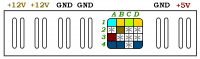
 From the left, as in the picture below. The two copper terminals are 12V outputs, the next two are ground / GND / RTN, then we have a "mysterious" 4x4 header, the next two are ground / GND / RTN and 5.1V.
4x4 header: A2, C2, D2, B3, C3, D3, C4 =
GND / GROUND - are marked with the sign "
* "in my drawing.
A1 = This pin raises my doubts. It is connected to two SMD resistors with a resultant resistance of 100 Ohm. In a word: the pin is of no use to us. The so-called pull down.
B1 = After connecting the power, this pin is high through a 10k pull up resistor connected to 5VSB inside.
C1 = Power_ON works the same as in the ATX power supply. To turn on the power supply, connect this pin to ground. This pin is connected to a 1k resistor inside, then the signal goes to transistor sot-23 and so on.
D1 = POWER_OK on the tested unit, the High signal appears here about 1.1 seconds after switching on with the Power_ON (c1) pin. It is probably an open collector output, watch out for this pin lest you burn the small sot23 transistor when fumbling with the meter ...
B2 = Analog input pin. Applies to the 12V line. After applying a current of 130..180uA to this pin, it causes a change of 12V output voltage linearly. The easiest way to describe it is: 0-130uA U_out_12V = 11.90V but when we give 180uA and more, the output appears about 12.15V. In a word: voltage regulation 12V. We don't have to use this pin, but the voltage will be 11.9V (that's exactly what I have).
A3 = Analog input pin. It applies to the 5.1V line. Same as above, but: current 10..40uA causes a change in the range of 5.10..5.23V. In a word: regulation of the 5.1V line.
The pins below are for the I2C memory soldered to one of the standing PCBs (specifically the larger PCB).
A4 = VSS of 24C02 chip
B4 = SCL
D4 = SDA
I haven't tested thoroughly if sometimes the uC STM7x also hangs on the I2C lines. Between pins B4, D4 and A4 there are 100 Ohm resistors between the chip, just in case. Note: A4 is not connected to GND / RTN ground.
To sum up: For proper operation of the power supply, it is enough to short PWR_ON with ground and hula. The rest are nice additions.
Below I present a photo:
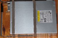
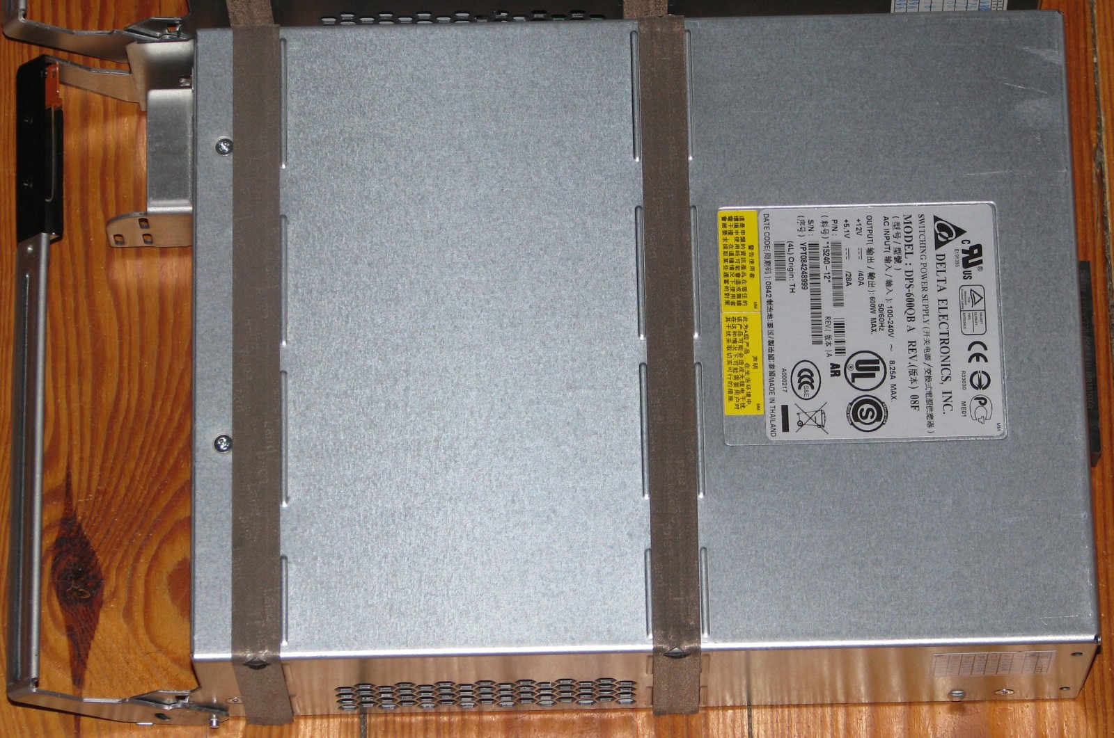
Here is the complete power supply. Huge dimensions (LENGTH x WIDTH x HEIGHT) [CM]: 30.5x20.9x6.9. The folded handle / handle is included in the length.
 1.jpg (469.77 kB)You must be logged in to download this attachment.
 Yes, Delta shows the parameters.
 2.jpg (176.78 kB)You must be logged in to download this attachment.
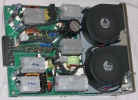
 Inside, after unscrewing EIGHT screws (one under the RF-shield, glued with double-sided tape). We see two beautiful Delta 12V / 2.94A turbines (i.e. cooling takes 30W at maximum speed). We can see the construction here: main PCB and two vertical boards. The larger one contains the ST72264G2 microcontroller, several LM324, LM358 op-amps, LM339 comparator (s), local 5V so-8 stabilizers, ST 2402 series I2C memory (2kB), its E0-E2 pins are connected to VSS, so from what I understand, the chip has an unlocked write (correct if I'm wrong here) and an SO-8 chip type TL384xB or TL284xB (I don't have a photo, I'm looking at the downloaded datasheet).
Output terminals. I managed to notice that the radiator, second from the right, in the photo below heats up more than the others. Three heat sinks in the lower half of the photo below connected to GND / RTN.
 3.jpg (510.64 kB)You must be logged in to download this attachment.
 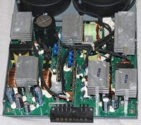 4.jpg (465.95 kB)You must be logged in to download this attachment.
 Two tiles. The smaller one contains mosfet drivers and full analog op amps and comparators. You can see LM324, LM358, LM339, local regulators and drivers, e.g. MIC4426.
 5.jpg (492.87 kB)You must be logged in to download this attachment.
 Bottom.
 6.jpg (523.59 kB)You must be logged in to download this attachment.
 You can see a good PCB layout, where the descriptions did not fit, tables were inserted. On the right you can see 4 pieces of resistance wire connected in parallel and tracks coming directly from them in order to measure the output current. I do not want to lie, but the right side suggests that the 12 V line is implemented as a two-bar converter (because you can see 2 coils and transistors and all this in pairs, symmetrically).
 7.jpg (846.61 kB)You must be logged in to download this attachment.
 PCB from uC by STM. By the way, the pins protruding upwards one after the other, as in the photo from the left:
1 16MHz sine,
2 I do not remember
3 ICCDATA (24th uC PIN)
4 ICCCLK (25PIN uC)
5 ICCSEL (26PIN uC)
6 VSS / GND / RTN
7 VDD (5V_SB) 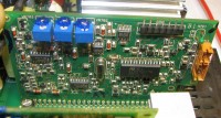 8.jpg (423.82 kB)You must be logged in to download this attachment.
 Shunt resistor, the so-called "Shunt resistor" with a small value, so as not to disturb the operation of the power supply at several dozen amperes. Looking at the date-codes, the power supply is from mid-2008 (the casing also has a type code, e.g. 0842 (42nd week of 2008)).
 IMG_84..jpg (223.12 kB)You must be logged in to download this attachment.
 I also found circuits on the PCB
UCC3895 and active PFC (power factor) controller
UC3854 from Texas.
That's enough for now. To sum up: good buy, good design, simple and reliable. But unfortunately very loud!
English:
BASIC way to make it work: just connect the C1 (pwr_on) with GND.
// UPDATE1:
NOTE: this is not a commercial action, I am writing to improve the quality of the forum, so that you can do yourself something useful if you have such a need. I anticipate the question: no, I do not sell these power supplies on Allegro, but I can see that many people have them on display, I also wish you fruitful hunting and trade negotiations

//
// ludek //


Comments
I used to work on the topic with the dell server power supply, I do not remember the model. In any case, there was a pin in the connector that had to be pulled up to ground so that the fans would run... [Read more]
I have a lot of server power supplies - bought or recovered mainly with the thought of taking care of it someday, if not starting it, acquiring valuable components. I will try to describe my buoys if... [Read more]
Server power supplies are enormous power, exceptional reliability and a ridiculously low price. About a year ago I bought a 550W Astec DS550-3 power supply that required a few modifications to: - obtain... [Read more]
While searching the internet for information about my power supply, I came across a few other tutorials and indeed in 4x3 pin plugs and probably 3x3 pin plugs it was possible to set the speed. It is possible... [Read more]
Do you think such a power supply can be converted to get symmetrical 20-30V? I have a similar one from the DELL server (12V 63A) but that one is much smaller, around 10x10x25cm. [Read more]
A friend is joking ?! I thank you for such advice ... I am talking more about changing the number of windings on the transformer and changing the voltage divider so that the power supply thinks it has... [Read more]
I understand that this may be it is dangerous and you can "let go of the hut with smoke", but this was the idea that occurred to me. As for the modification of the output voltage of the power supplies:... [Read more]
Well, this is how I put together my knowledge about the DS550-3 (Dell A23300) and how much col. michael111 he will not mind, I will present here: 1. Raising the output voltage to 13.8V. I will... [Read more]
You can connect two in series on each side. [Read more]
How many times should I repeat that I mean remaking one and not putting two in a row? I am only interested in whether something needs to be changed in the system, apart from deceiving the power supply... [Read more]
In my opinion, it is easier to make a converter, I think for audio from scratch. You would have to scroll the trafo, change the LEDs, etc. In addition, it's not the pp system. So I feel that the secondary... [Read more]
@prosiak_wej - thanks, it's okay. May someone use what you posted. [Read more]
Can you expand the abbreviation pp? I still don't understand why, the voltage in the socket remains the same, and so does the current. So the current through the transformer will not change. The... [Read more]
It's probably about push pull. [Read more]
push-pull. This is probably a flyback power supply. on the same board you will solder the diodes? You also have to wind a symmetrical Dałwik. It is easier to convert the Chinese ATX, at least the known... [Read more]
Hello Regarding the taming of this type of power supply :) For some time I have had a power supply identical to the one described in this thread: http://www.elektroda.pl/rtvforum/topic2155589.html ... [Read more]
@ Qurak - a real monster :) He will probably be able to add FAN regulation. If so, with a bit of jamming, you can insert a processor, a temperature sensor and adjust the speed of the fans depending... [Read more]
In this case, it's not that simple, I have a DELL PE2950 server myself and since it has a total of five fans, each 12V, 2-3A, about 6k RPM, when they start at full speed, we have a small jet that straightens... [Read more]
I do not know what specific fan you write about in this server, but there are four-wire ones, you regulate the speed by giving PWM on the blue wire: http://obrazki.elektroda.pl/4047114700_1486471579_thumb.jpg... [Read more]