As part of the ongoing competition
contest at elektroda.pl there is a chance to get an Arduino Uno module, the module is equipped with an ATMega328P microcontroller clocked with a 16MHz quartz resonator, 5V power supply. There is a USB-B socket on the board that allows for power supply and communication (sending the program from the Arduino environment, or communication with the running program). The DC socket allows for power supply with voltage higher than 5V (AMS1117 stabilizer). The board is equipped with a USB UART converter, which facilitates integration with the Arduino environment. Connectors on the board allow you to connect expansion modules (shield). On the board, there are LEDs informing about the presence of power, activity on the RX / TX lines of the UART interface and the LED connected to the D13 pin. The microcontroller and its I / O ports work with a voltage of 5V, additionally there is a 3.3V supply voltage, however, care should be taken to convert logic levels for systems powered by voltages other than 5V. There is a reset button on the Arduino Uno board, the ISP connector allows you to put the program using the programmer, using ISP you can change the fusebit settings of the microcontroller (e.g. change the clock source to the internal RC generator) and even give up the bootloader or Arduino environment and send the compiled code written in e.g. Atmel Studio 7.0. The USB UART CH340 converter was used and if there is no driver in the system, they are available on the manufacturer's website:
information about CH340 documentation Windows drivers Linux drivers If the driver is installed correctly, a new serial COM port will appear in the system after connecting the module.
We are downloading the current version of the Arduino environment, (currently
1.8.4 ),
then create a new program (sketch) and select the Arduino / Genuino Uno board:
Tools-> Board-> Arduino / Genuino Uno
Next:
Tools-> Port-> and select the COM port on which is the board connected to the USB.
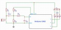
Arduino Uno schematic -
source .
For the first attempts to flash the LED, you can use sample programs made of material o
Arduino nano. you will find there examples of how to flash the LED, how to smoothly change the LED brightness and how to flash the RGB LED to the beat of the music.
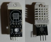
Humidity and temperature sensor AM2302 (DHT22) The AM2302 sensor can work with voltages of 3.3-5.5V, it has 4 pins (one unused). Three outputs are used as power supply (1), data transmission (2), and ground (4), more you can find in the catalog note:
AM2302 .
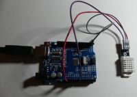
The pin used for data transmission should be connected to the power supply through a 5.1kom resistor, DHT22 often appears as a module mounted on a board with three pins, usually on the board there is a resistor pulling the pin "data" to "+", so in the case of a module to connect to Arduino it is enough only three wires (power, data, ground).
The length of the connection cables can be up to 20 meters. Relative humidity measurement in the range of 0-99.9% is performed with a resolution of 0.1% and an accuracy of + -2% at a temperature of 25 degrees C (the error increases at low and high humidity). Temperature measurement in the range of -40 to 80 degrees with a resolution of 0.1 degrees C and an accuracy of + -0.5 degrees.
In the example we will use the Arduino digital output "2" to connect the DHT22 data line.
To make our work easier, we will use the library to handle the sensor:
Sketch-> Manage Libraries-> Library Manager
We search for the phrase "dht" and select "SimpleDHT by Winlin"
More information about the library here:
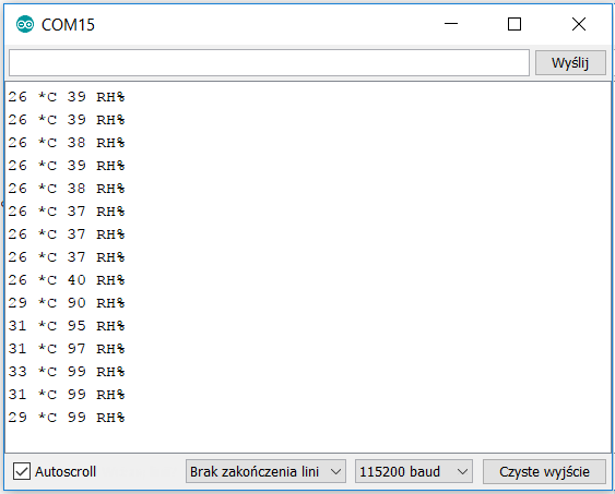
https://github.com/winlinvip/SimpleDHT Below is an example of a code that downloads data from a sensor, after its launch in the monitor of the serial port, we will see information about temperature and humidity:
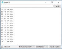
A humidity sensor during the heating season can help you decide to start the air humidifier. A sensor outside your home can help you forecast the weather, a large increase in humidity with a drop in pressure can indicate a stressful storm.
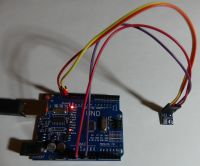
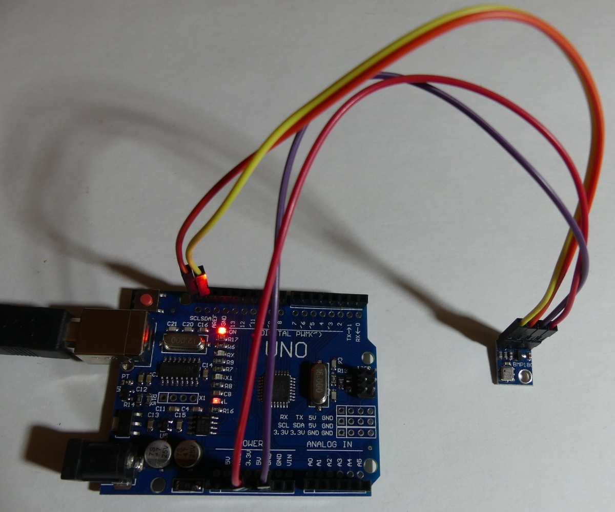
Temperature and pressure sensor BMP180 The sensor allows temperature and pressure measurement, I2C interface used, 1.8-3.6V supply voltage, more in the application note:
BMP180 . The sensor mounted on the GY-68 board has additional electronic components to facilitate the connection of the sensor with Arduino Uno. We connect the GND lead to the ground, VIN to the 3.3V output of the Arduino board, the I2C bus lines to SDA and SCL, respectively.
We include a library to support the BMP180 sensor:
Sketch-> Manage Libraries-> Library Manager
Search for the phrase "BMP085" and select "Adafruit BMP085 Unified by Adafruit"
More information about the library here:
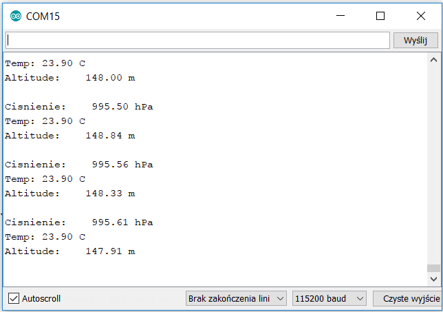
https://github.com/adafruit/Adafruit_BMP085_Unified Sample code to display sensor data in the serial port monitor:
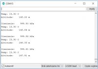
Observation of pressure changes can help in forecasting the weather, a systematic drop in pressure can be a sign of impending deteriorationweather and precipitation, systematic pressure increase can predict sunny weather and no precipitation. Rapid changes in pressure (from 4hPa within 3 hours) may indicate incoming winds with the force depending on the suddenness of pressure changes. There is also something like "normal" pressure for a given location (depends on altitude above sea level), based on this value, you can make a simple forecasting method, if the pressure read from the sensor oscillates + -10hPa around the "normal" pressure, you can expect cloudiness / moderate pressure weather, if the read pressure is higher by more than 10hPa than "normal" then we forecast sunny weather, while lower by 10hPa than "normal" forecasts rain / snow. Normal pressure is 1013.25hPa at 0n.pm.For your city, you can calculate the "normal" pressure using
barometric formula here online:
http://www.altitude.org/air_pressure.php you can calculate "normal" pressure at a certain altitude under normal conditions.
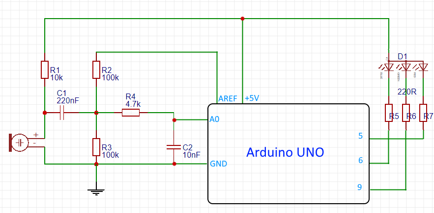
RGB LED color phone use FFT Let's perform FFT analysis of the signal from the microphone supplied to the ADC A0 input of Arduino. The results of the FFT transformation will allow you to drive the RGB LED to the rhythm of the music using PWM (R-pin5, G-pin9, B-pin6). A detailed description of the FFT can be found here:
FFT on ESP32 and Arduino .
On the Arduino uno we will sample the output signal with a frequency of 8kHz which will allow the analysis of frequencies up to 4kHz, the length of the sample buffer for FFT will be 32 which will result in 16 points of the FFT result. The "arduinoFFT" library should be added to the Arduino environment. In the video below you can see the reaction to example music:
Link [movie: c1dfeb3d29]
https://filmy.elektroda.pl/52_1508085054.mp4 [/ movie: c1dfeb3d29]
Below is a test code with which you can experiment, for example, making the degree of PWM filling dependent on selected different frequencies:
R4-C2 form a low pass filter to adapt the input signal bandwidth to the 8kHz sampling frequency.
 What ideas do you have for using the Arduino Uno?
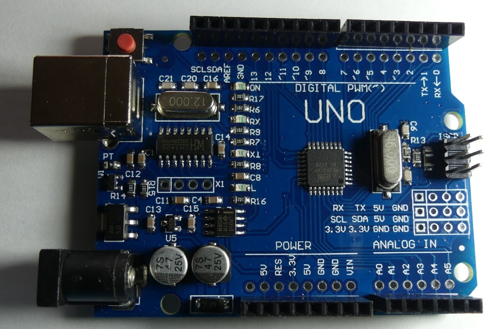


Comments
It would be appropriate to include a diagram of the arduino itself. [Read more]
Ideas like everything else, America will not be discovered here ;) Depending on the needs, but still rather for hobby games or some prototype devices. I would like to make a controller for a pressure coffee... [Read more]
@piotr_go typical diagram for Arduino UNO, only CH340 was used as a USB UART converter, I am not a fan of this converter, but its use has a positive effect on the price, I prefer, for example, CP2102... [Read more]
I prefer FTDI. I have never had a problem with them (from the system side), which is not so obvious in the case of other converters (especially the popular PLxxxx). And I can get to FTDI through D2XX libraries.... [Read more]
CH340G is very cheap and, interestingly, it works "kick". I used to be afraid of such cheap modules, but if they are popular, it means that they work :) FTDI-based converters have many unused function... [Read more]
Diagram for people not using the arduino environment, so that the pinout is at hand. Besides, I was wondering why the LM358? (I already found it) [Read more]
In the family of converters belonging to the CH340, there are circuits with SPI, IIC. It is true that you cannot choose the configuration of the system from the microcontroller side as in FTDI, but it... [Read more]
@Mikroprocesorowiec I got discouraged by FTDI when they launched the action of breaking devices based on FTDI counterfeit products, https://www.theregister.co.uk/2016/01/31/ftdi_accused_of_bricking_counterfeits_again/ ... [Read more]
I have not heard about it and this is interesting information. SaleAE software does the same, but there is a way. As for FTDI, fortunately USB-USART is counterfeit, and I use USB-IIC / SPI and VNC2. [Read more]
https://obrazki.elektroda.pl/2448011400_1508348640_thumb.jpg Source [Read more]
Thank you, I added a link to the schematic in the first post. [Read more]
I had several FT232 devices, all of them from the PRC - and there are allegedly only fakes. Drivers only from FTDI, I never had any problems, no device failed. [Read more]
But what FT232? It can be BL (if you don't connect external eeprom, it can't be "broken"), FT232RL has eeprom inside, so that's another story. I do not think that the program itself in FTDI... [Read more]
RL. For the most part, it was in EEPROM that I was looking for, out of curiosity ;) [Read more]
Do you know the memory map? There you can change VID, PID, CBUS functions, etc. The configuration area protects the CRC and in case of bad it restores the standard, but it is close to 1kB for any use.... [Read more]
I only used mprog, nothing else interested me. Some crap out of curiosity about what I needed, just that. [Read more]
Can this sensor, the AM2302 sensor - be put out of the window. The circuit board will deteriorate quickly. What's the way? [Read more]
It is more of an internal sensor, but if it were in the right cage / housing it would have a chance to work. [Read more]