
Good morning,
Today's presentation concerns my final version of an amateur oscilloscope and a generator based on an external USB sound card.
Seemingly nothing special as for today's times, but the device is easy to install, inexpensive, and most importantly useful.
Device parameters: OSCILLOSCOPE:
Channels: 1
Vpp max: 25V
R in:> 1M Ohm
Frequency: 20kHz
Divider: x1 (5 Vpp max) x5 (25 Vpp max)
GENERATOR
Out Vpp: 0 - 10V
Frequency: 20Hz - 20kHz
Waveforms: Rectangle, Sine, Triangle, Noise
The frequency of the generator and the oscilloscope depends on the sound card.
These are for reference only. In practice, the useful frequencies are much lower.
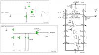
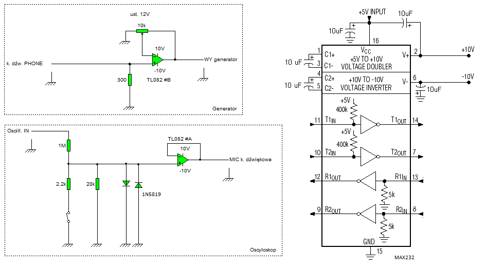
Construction: The device consists of a symmetrical power generator based on the well-known Max232 chip. It is quite an unusual application of this cube, but its choice was impressed by the modest number of external components, low price, and quite stable output voltage. However, it should be remembered that the maximum output current of the internal converter does not exceed 10mA. In this case, this small current is more than enough. Another important element powered by the Max inverter is the TL082 dual operational amplifier.
One amplifier (A) acts as a voltage follower, acting as the oscilloscope input buffer, and the other half (B) of the cube acts as an amplifier for the waveform generator, making it possible to obtain an output amplitude of 10Vpp. The oscilloscope input of the amplifier is equipped with two dividers. The first one allows you to measure voltage up to 5Vpp, and the second one up to 25Vpp - they are switched using a jumper on goldpins. Additionally, the oscilloscope input has been protected by two 1N5819 diodes against voltage higher than 1Vpp. However, this does not exempt us from being careful when taking measurements.
I emphasize that I am not responsible for any damage resulting from the operation of the device. You use the material provided here at your own risk.
 Sound card selection:
 In principle, you can use any. However, it is worth bearing in mind that the one with which you can remove the DC component filter, both on the microphone input and on the headphone output, is better. The DC component filter causes that the input cannot be given DC voltage. As a result, the rectangular graph will not resemble it at all, the sine wave will have characteristic "spouts" at the top, and the triangle will lie on the right side. In my copy, it was only possible to partially remove the input filter. Unfortunately, not at the output, which can be seen on the oscillograms from the generator.
Cards that I tested:
3D Sound - filters cannot be removed
GreEw Counterfeit (currently) - can only be partially removed from the MIC input. Apparently, the original one can completely get rid of the input filter. About the output filter, I have no information.
Measurement: It is known for a long time that the sound card was designed for slightly different purposes than those described here

. This does not mean, however, that it is completely unsuitable for measurements.
It is true that the results will have a slight error, but it is a cheap amateur device.
After installing the device, unfortunately, you cannot expect that it will correctly measure the input voltage, because it must be properly calibrated.
Calibration: Let's start by setting the generator output amplitude, which will then serve as a reference. To do this exactly, it is best to use a commercial oscilloscope, but most people interested in making a device do not have one. However, there is an alternative way to calibrate, unfortunately less accurate.
1. Connect the device to the computer and then run the "Generator.exe" program.
2. In the program, set the amplitude to max, Sinusoidal waveform, and frequency exactly 50Hz.
3. Apply the AC voltmeter to the generator output and set the potentiometer on the board to 10V. Don't turn off the app!
This way we have a fairly accurate reference voltage that can be used to calibrate the oscilloscope.
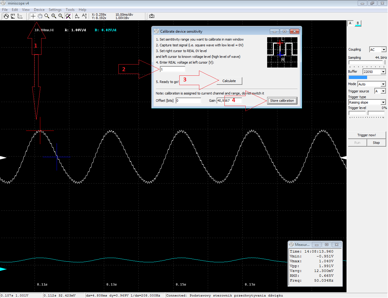
1. Put a jumper on the x5 divider, connect the generator output with the oscilloscope input, and then run the Miniscope.exe program
2. Using the "paw" from the upper bar, set the visible waveform in such a way that it is easy to determine its half (actual crossing through 0), and then select the "crosshair" from the upper bar.
3. Right-click where the graph should go through "0" and then left-click at the top of the sine.
4. From the menu select Tools -> Calibrate Sensitivity, and in the field under point 4 enter 1. Click the "Calculate" button, and then "Store Calibration"
[10 (Uwe) / 5 (5 divisor) / 2 (two halves of the chart) = 1]
To check the correctness of the indications, the current Vpp index should be multiplied by 5, and the output should be about 10V, which is as much as it really is.
 Oscillograms:
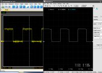
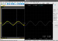
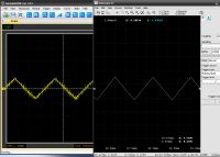
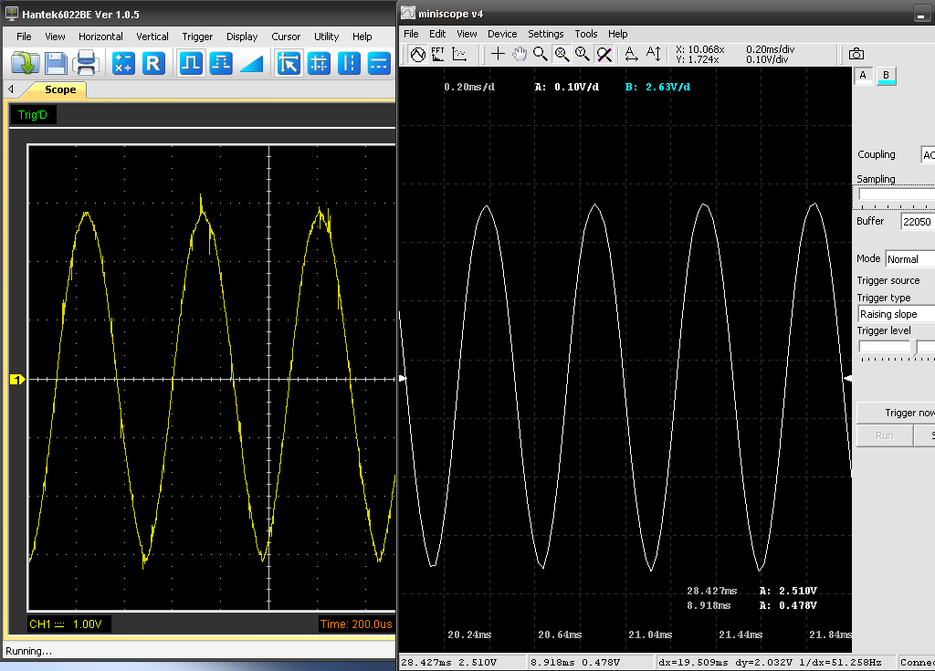
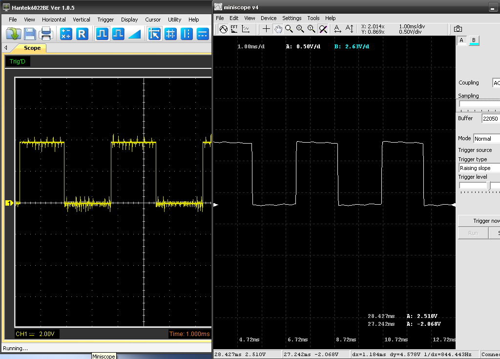
 Below is a collection of oscillograms showing the actual graphs from the mini oscilloscope and the generator. As a comparative oscilloscope, I used a commercial "Hantek 6022".
As a signal source for the oscilloscope, I used a generator once presented in the pages of the "Elektronika Praktyczna" magazine (once I presented my performance in the DiY section).
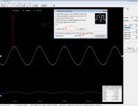
Oscilloscope, approx. 2kHz:

]
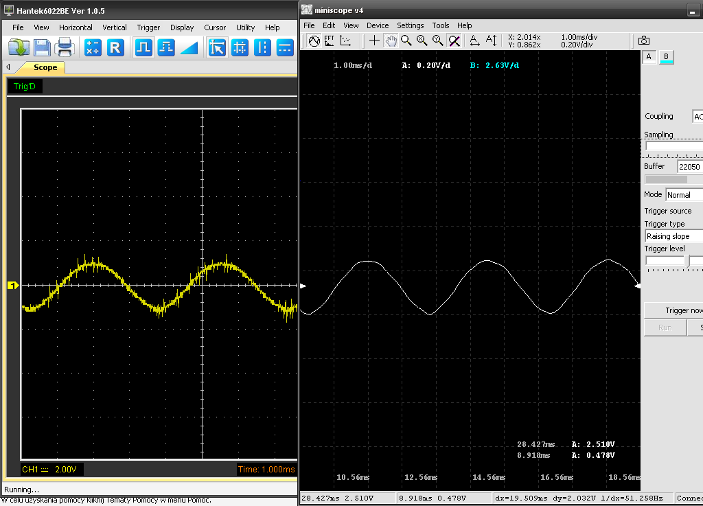
Oscilloscope, approx. 300 Hz:
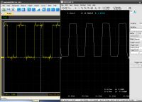
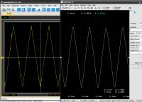
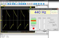
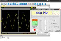
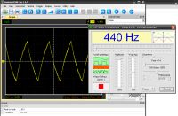
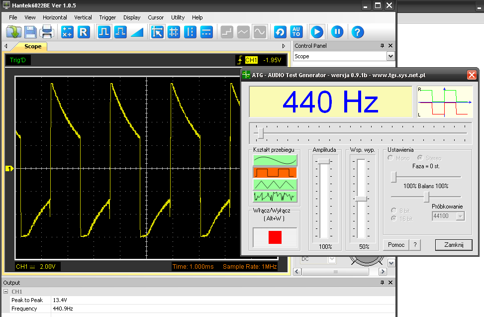
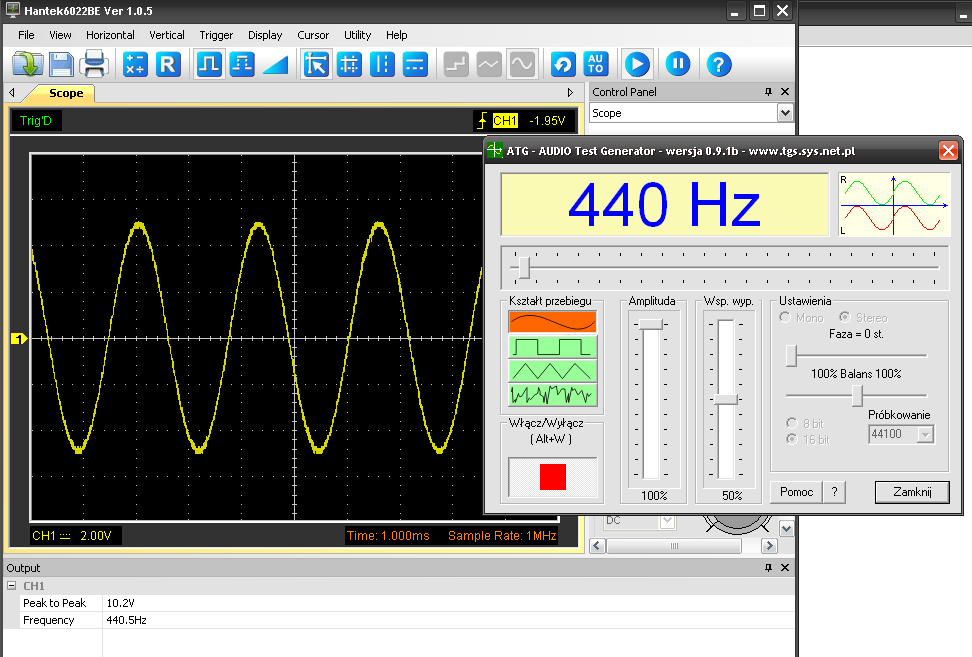
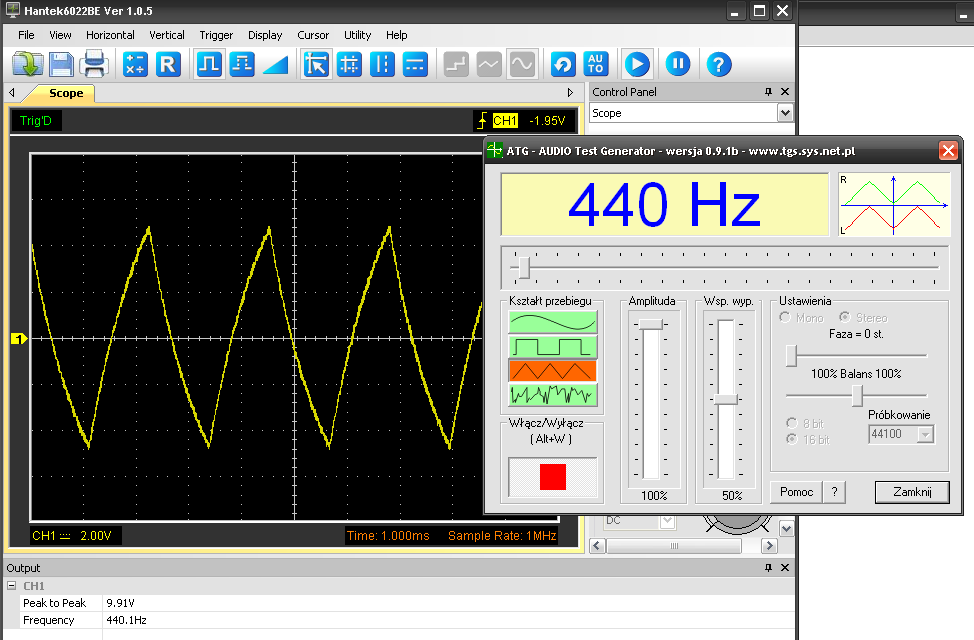
Generator, 440Hz:
The graph showing the rectangular and triangular graph shows the undesirable effect of the constant component filter.
The whole thing looks pretty nice, for PLN 20 worth of it
I encourage you to implement and comment on my project
Best regards,
Łukasz Górecki
Links:
http://tomeko.net/miniscope_v4/ - "Miniscope" application written by Mr. Tomasz Ostrowski. This is the best app to turn your sound card into an oscilloscope. Congratulations to the author !.
http://tomeko.net/dsoundscope/C_Media2/ - Description of getting rid of DC component filters in the GreEw card (C-Media)
http://www.tgs.sys.net.pl/ - The "Generator" program
In the attachment, all necessary materials and applications.


Comments
Value for money just great. Congratulations on a very successful construction. [Read more]
Cool cheap and looks effective. I had this Hantek so I suspect yours works better - maybe not this range, but still :-) However, I have a question, what is the use of an additional amplifier before... [Read more]
I would like to say hello to everyone (first post). I have some doubts about the method of simplified calibration. The AC voltmeter shows the effective voltage. We calibrate the amplitude. It seems... [Read more]
I am not the author of the application, but it seems to me that he shares the source on his website. http://tomeko.net/miniscope v4 / (the address is at the end of the post). Yes ... this calibration... [Read more]
At what sampling rate is the above true? Because at 44.1kHz you are not completely able to judge the shape of the 20kHz signal because that gives 2 samples per period. At 192kHz (if the card has one) I... [Read more]
What about phase inversion of the signal through the sound card (MIC input)? I had this problem myself and it is quite common (supposedly it is a software issue - drivers, but I did not study this topic).... [Read more]
You can't call it an oscilloscope or a generator. Oscilloscope: - DC coupling where is it? - triggered by an external signal? The simplest oscilloscopes have such functions. Generator: ... [Read more]
Therefore, 192kHz sampling can and must be used. Then it starts to make sense and you can analyze something. Let it be for 10 - 20 PLN and even fun :) The problem is that you can buy an analog... [Read more]
Hello, Your criticism is not unfounded, and it is actually hard to call the device that I presented an oscilloscope, or a useful generator. However, it must be remembered that this is an amateur toy... [Read more]
Stop hanging the dogs on @goreckidiy :) According to the PWN dictionary: an oscilloscope is an instrument for the observation and measurement of electrical waveforms According to... [Read more]
My friend COMPLETELY did not understand my speech. Totally. [Read more]
Fact. Excuse me ;) [Read more]
There has been a misunderstanding ... With this digression I wanted to make all the critics realize how much would cost what they criticized in your appetizer. I wanted to show that even these super "oscilloscopes"... [Read more]
Hey, not everyone can afford a device worth 1000+, and here it is cheap, simple and that it has disadvantages, as even super expensive gems will have them and that's it. After all, you can see a lot... [Read more]
Cool design! Can you describe how you removed the filters on your soundcard and where less were they? [Read more]
As I mentioned in the first post, I only managed to get rid of the DC component filter only partially. Unfortunately, I do not have a photo, and I would not like to desolder the card from the board to... [Read more]
I just have a stationary machine, I was thinking about a PCI sound card and they are more susceptible to modifications :) [Read more]
Not all. On the website of the author of the miniscope program, you can find descriptions for various cards (link to a foreign page with descriptions). It seems to me that the usb is better. You'll... [Read more]