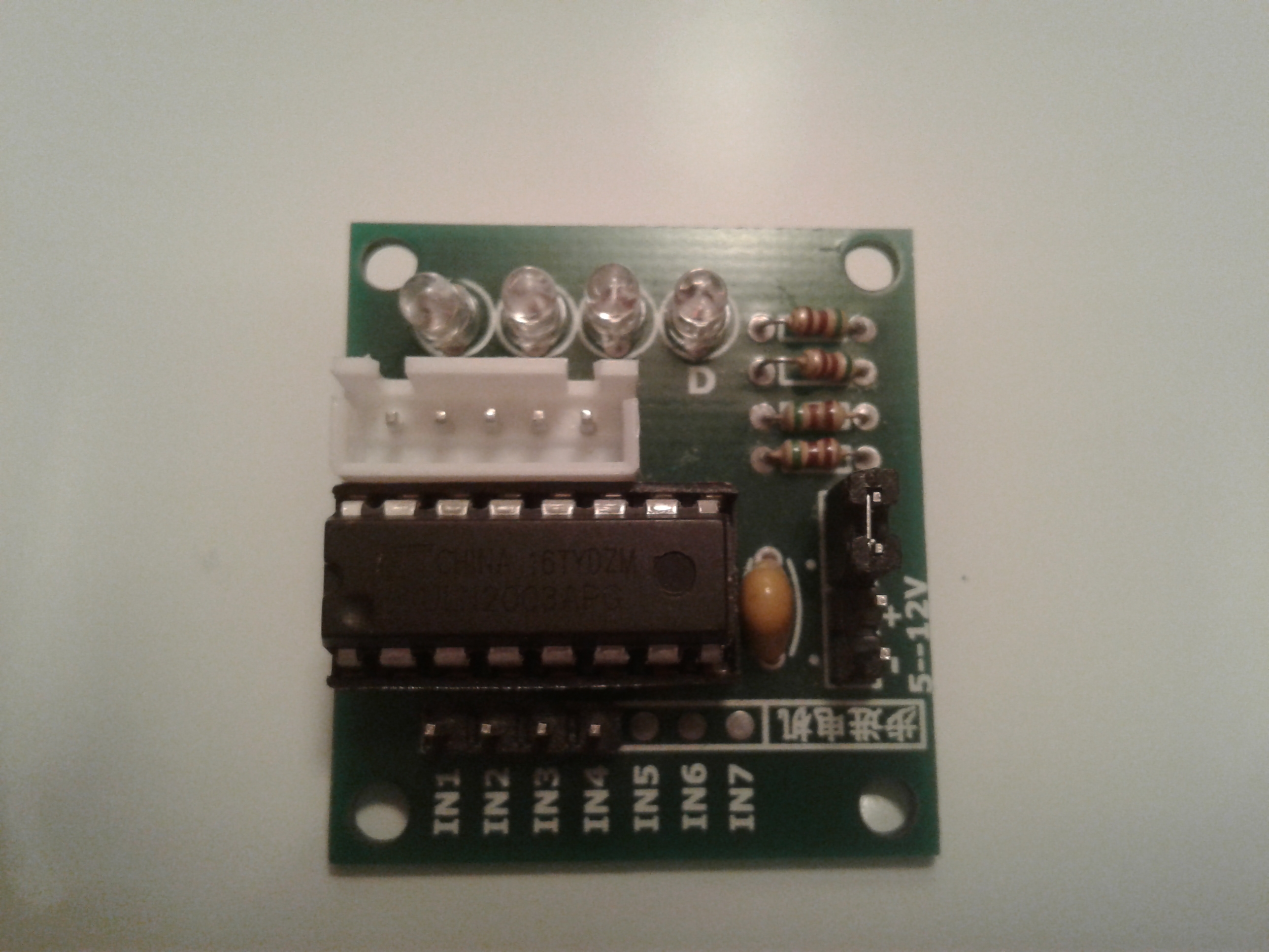
A ULN2003A-based module drives the 28BYJ-48 unipolar stepper motor through IN1–IN4 and a JST-XH-05 connector.
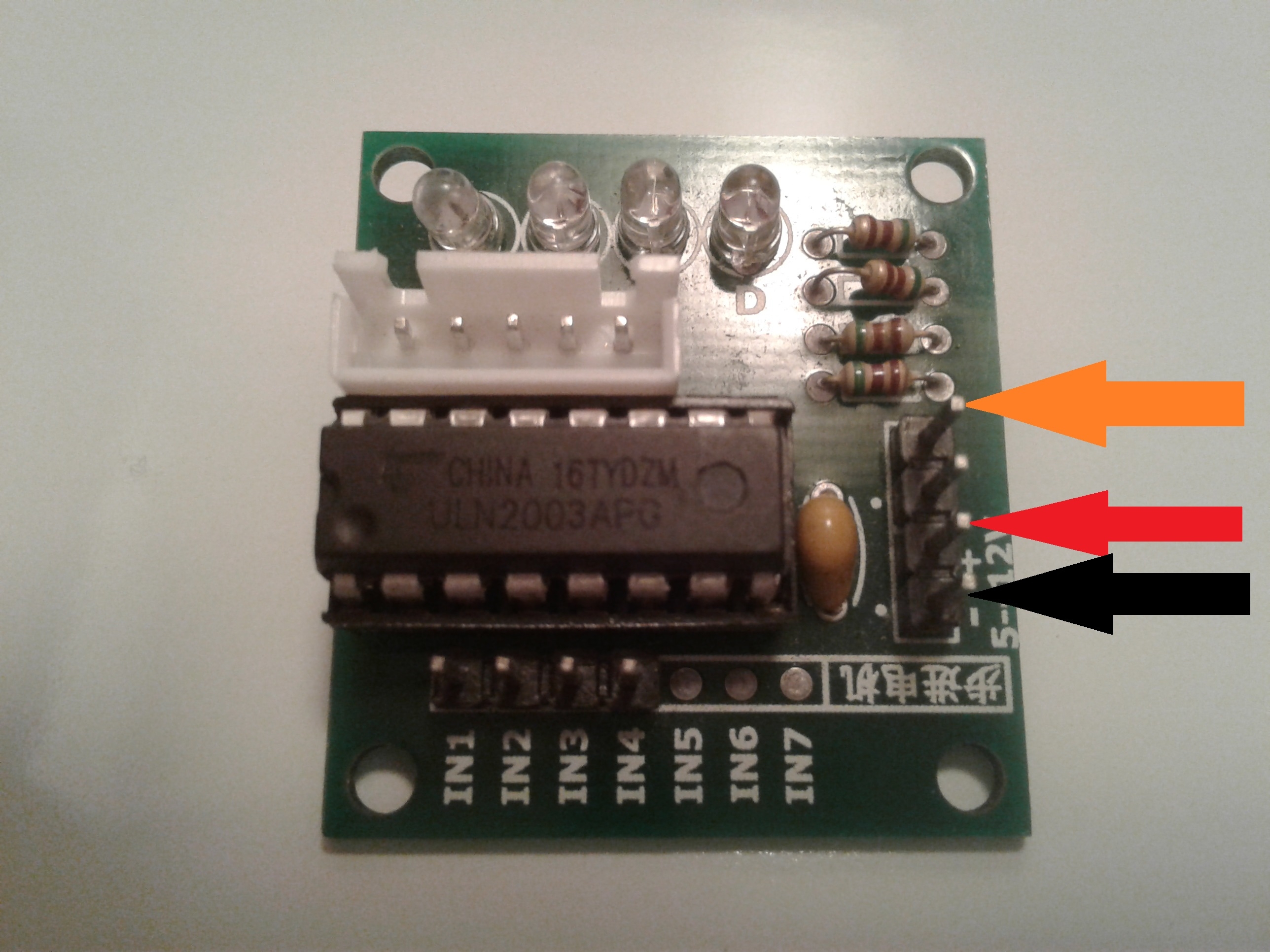
A jumper can tie motor power to the controller supply, while LEDs A–D indicate each output and the red wire serves as the common coil connection.
The board measures 40.5x23 mm, accepts 5-12V on the controller supply, and the ULN2003A output current is limited to 500mA.
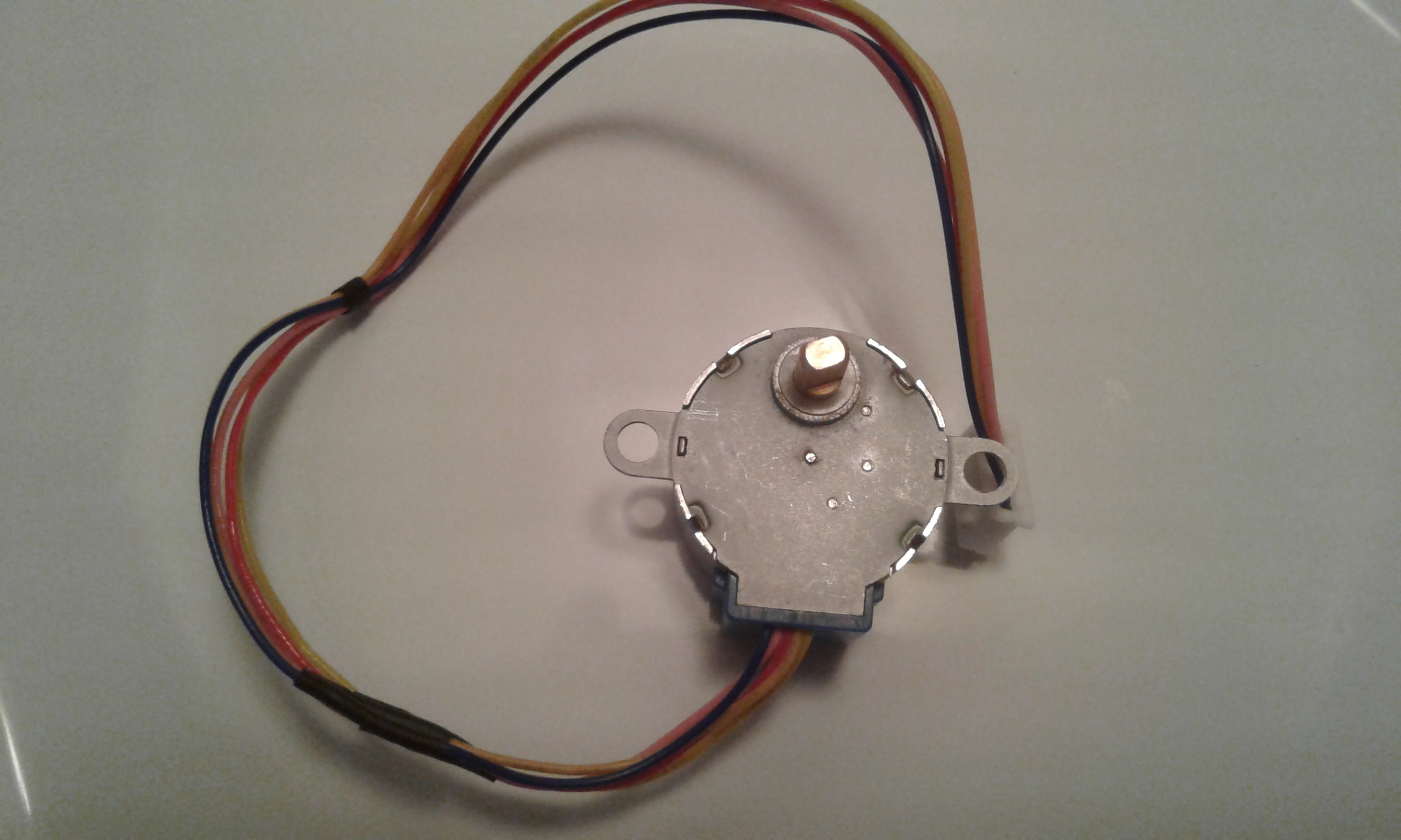
The 28BYJ-48 is a 4-phase, 0.03 Nm motor with 11.25° steps and a 1:64 gearbox, needing 2048 steps for one output revolution.
Wave, full-step, and half-step control are demonstrated in Bascom, and half-step uses 8 ticks per cycle with smaller steps and less resonance.
Summary generated by AI based on the discussion content.
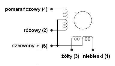
Here I present to you one of the most popular modules used to power a unipolar stepper motor. The module and the stepper motor can be purchased from China for less than $1.50 including shipping, and are also available on Allegro and other auction sites. The dimensions of the board are 40.5x23mm. There are two goldpin strips on the board. One four-pin is used to control the motor where we have inputs from IN1 to IN4, the other four-pin is the controller power supply (+,-) and a jumper (the jumper inserted is the motor power supply equal to the controller power supply) on this strip to power the motor where we can take it from the controller`s power supply, which according to the manufacturer should be in the range of 5-12V, or from the outside, but remember that the voltage cannot exceed 50V - higher voltage may damage the ULN2003A system, you also need to pay attention to the current when using a different motor - the maximum current from ULN2003A is 500mA. We can use the higher power supply to power another engine, our tested engine is 28BYJ-48 where the power supply for it should be 5V. Description of the goldpin power strip - red arrow - plus, black - minus, orange - engine power. In addition, there are 4 LEDs on the board to visualize what is happening at the outputs of the system. The motor is connected to the controller via the JST-XH-05 connector. The module works in a very simple way. After applying a high state to the IN1 input, we obtain a low state on the motor connector where the blue wire is connected, this is signaled by the activation of LED A. Applying a high state to the IN2 input causes a low state to appear on the pink wire, which is signaled by LED B. Applying a high state to the IN3 input causes a low state to appear on the yellow wire, which is indicated by LED C. Applying a high state to the IN4 input causes a low state to appear on the orange wire, which is indicated by the LED D. The red wire is a common connection for all four coils. Here we have the plus from the module power supply through the jumper on the goldpin strip powering our controller. As for the motor, it is a four-phase motor with a power of approx. 0.03 Nm with a step of 11.25 and a gear ratio of 1:64, which means that with e.g. wave or full-periodic control, we have to take 2048 steps to make a full revolution at the gear output. Now a little theory to know how to use it. Stepper motors can be divided into unipolar and bipolar. Controlling unipolar stepper motors is easier and less complicated than bipolar motors. In a stepper motor, the speed does not depend on the value of the supply voltage but on the frequency of steps, and the direction of rotation depends on the sequence of steps. In this description, I will present how to control a unipolar motor in waves, full steps and half steps.
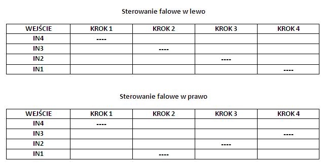
Wave control. In wave control, also called single-phase control, only one coil is always powered, i.e. only half of the winding from one pair is used in each step. It can be said that with this type of control we use only ¼ of all available motor coils/windings. The control is quite simple, but using it reduces the performance of the engine used.
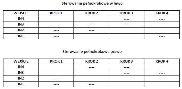
Full step control. In full-step control, also called two-phase control, two stepper motor coils are always powered. It should be noted that here we never power two coils from one pair at the same time. This type of control allows us to use our engine more. In this case, two of the four windings are always working, which means we use half of the available motor coils/windings.
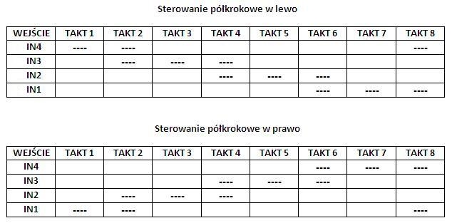
Half-step control. As you can see, half-step control is more complicated than wave and full-step control. This control is a combination of the two previously described controls. In the case of such control, we have a twice shorter step, which gives us greater accuracy, we obtain a smaller effect of engine resonance, which is more visible in wave or full-step control. While in single-phase or two-phase control, where the sequence of control signals is repeated every four ticks, in half-step control it is repeated every 8 ticks. When using half-period control, compared to the controls described earlier, at the same frequency of control signals, the engine speed is twice as slow.
Below is a program written in Bascom by forum member " ~~~pio~~~ ” (who agreed to use it here) where we can test our module with the engine using the types of controls described above. I added a few descriptions to the program so that it could be easily converted to any type of control described here.
Code: VB.net
Log in, to see the code
Below are videos showing the use of the set and each of the described controls.
Wave control.
Full step control.
Half-step control.
About Author
grala1 wrote 9816 posts with
rating 5049 , helped 1495 times.
Live in city Kalisz.
Been with us since 2006 year.
I do not understand why it is called a driver, since this device does not control the engine, but only "powers it" (or more precisely, it amplifies the signal from the CONTROLLER) ... [Read more]
grala1
26 Nov 2017 16:23
I corrected the title and content.
In fact, I duplicated a common error in the network - it is not a stepper motor driver, but only a power module.
I am sorry for misleading. [Read more]
levy^
28 Nov 2017 17:56
Very nice, cheap and working set that powers my 30-year-old speedometer [Read more]
anszun
30 Aug 2021 13:47
Col. Grala1 please help. The controller has 4 power pins. there is a jumper on the third and fourth. I want to start it at 12V. Is it enough to remove the jumper or change the pins? When connecting pin1... [Read more]
TallyFeli
17 Nov 2021 19:06
Hi...Amusingly, relatively few individuals really realize how to function with them. What's more, in case you are an absolutely confused fledgling with regards to hardware, we comprehend that perusing... [Read more]
RAPER
05 Apr 2022 19:55
Hello
I see that my friend, Levy ^ did something I need, but he doesn't speak, so maybe someone else will help. I need such a kit for the old rope meter, because I cannot connect it anymore. Will... [Read more]
levy^
06 Apr 2022 10:16
I contacted PW after 16 hours of receiving your message, I can be independent of notifications on the phone :-) [Read more]
mjab
08 Sep 2022 11:36
Hello,
uses these motors in internal blinds. And here I have a question, if I increase the motor voltage from 5v to 10v, it will raise its Nm? My guess is that it will also heat up more, but its work... [Read more]
levy^
08 Sep 2022 11:49
No, you will burn the windings, increasing the torque of a stepper motor is something else entirely. [Read more]
mjab
08 Sep 2022 17:40
OKAY :) , and more specifically how to raise a Nm in such a motor?
For now, my friend made me realize that I am .... yyy ... silly :P And now I would like to be wiser about this knowledge :)
To give... [Read more]
levy^
08 Sep 2022 19:42
You can use half steps or full steps, reduce the speed, check the maximum torque in the documentation for this engine. I was just reducing the torque because I mechanically block the drive to determine... [Read more]
mjab
08 Sep 2022 21:08
Well, the point is that the internal blinds should close and open as soon as possible. The normal closing time of the roller shutter in a standard window is about 90 seconds. I would like to cut it down... [Read more]
zdziwiony
09 Sep 2022 10:12
First of all, use some normal stepper motor driver, for example stepsticks used in 3D printers. Secondly, use stepper motors with the lowest possible operating voltage, and supply the controller with the... [Read more]
1. Is the ULN2003 board a driver or merely a power stage?
It is a Darlington transistor array that amplifies control signals; sequencing still must come from a microcontroller or PCF8574A. Calling it a “driver” is common but inaccurate [Elektroda, szymon122, post #16848816]
2. What is the correct pinout for the ULN2003A module?
IN1-IN4 accept 3–5 V logic. The four-pin power header carries Vlogic (+), GND (–), VMotor (orange), and a jumper that links Vlogic to VMotor for single-supply use [Elektroda, grala1, post #16847267]
3. How do I run the board with 5 V logic and a 12 V motor?
Remove the Vlogic-VMotor jumper, feed 5 V to the ‘+’ pin, 12 V to VMotor, and common ground both supplies. Leave IN1-IN4 at 5 V. All LEDs lighting without I²C control means VMotor floats through LED circuits—re-check grounds [Elektroda, anszun, post #19587419]
4. Will a 5 V 28BYJ-48 survive 12 V operation?
No. Users reported burned windings when exceeding rated voltage [Elektroda, levy^, post #20180507] The coils measure about 50 Ω, so 12 V would quadruple power to 2.9 W and overheat them [28BYJ-48 Datasheet].
5. How many steps per revolution in each drive mode?
Use a step-stick driver (A4988/TMC2208), set current to 100 mA, and drive the motor from 12 V with proper current limiting. “Use a ramp so the engine does not start at full speed” [Elektroda, zdziwiony, post #20181773]
8. Can this kit replace a cable speedometer using an ABS sensor?
Yes, if a microcontroller converts ABS pulses to step sequences. ABS sensors output frequency, so you must scale pulse rate to step rate that spins the motor-gear assembly and gauge needle [Elektroda, RAPER, post #19965660]
9. What maximum speed is realistic?
Most 28BYJ-48 motors stall above 15 RPM in full-step at 5 V. Lab tests show reliable operation up to 12 RPM with 70 mN·m load [MKR Lab, 2021].
10. What happens if I exceed 500 mA or 50 V on ULN2003A?
The Darlington transistors enter secondary breakdown and short, often pulling all coils low—an irreversible failure [Elektroda, grala1, post #16847267]
11. Why did all four LEDs light when I connected 12 V?
With jumper removed, 12 V fed the LED common anode but logic inputs floated high, turning every channel on. Tie logic ground to motor ground and drive IN1-IN4 low to extinguish them [Elektroda, anszun, post #19587419]
12. How do I switch between wave, full-step and half-step in software?
13. Does higher supply voltage always increase torque?
Only if current is limited and motor supports it. For high-impedance 28BYJ-48, torque depends mainly on current, not voltage. Excess voltage without current control burns coils [Elektroda, levy^, post #20180507]
14. Are there failure edge-cases to watch?
Reverse supply polarity kills the onboard LEDs instantly; shorted coils can drag ULN2003A outputs low and heat them above 150 °C, triggering thermal runaway [Texas Instruments, 2020].
Summary generated by AI based on the discussion content.
Comments
I do not understand why it is called a driver, since this device does not control the engine, but only "powers it" (or more precisely, it amplifies the signal from the CONTROLLER) ... [Read more]
I corrected the title and content. In fact, I duplicated a common error in the network - it is not a stepper motor driver, but only a power module. I am sorry for misleading. [Read more]
Very nice, cheap and working set that powers my 30-year-old speedometer [Read more]
Col. Grala1 please help. The controller has 4 power pins. there is a jumper on the third and fourth. I want to start it at 12V. Is it enough to remove the jumper or change the pins? When connecting pin1... [Read more]
Hi...Amusingly, relatively few individuals really realize how to function with them. What's more, in case you are an absolutely confused fledgling with regards to hardware, we comprehend that perusing... [Read more]
Hello I see that my friend, Levy ^ did something I need, but he doesn't speak, so maybe someone else will help. I need such a kit for the old rope meter, because I cannot connect it anymore. Will... [Read more]
I contacted PW after 16 hours of receiving your message, I can be independent of notifications on the phone :-) [Read more]
Hello, uses these motors in internal blinds. And here I have a question, if I increase the motor voltage from 5v to 10v, it will raise its Nm? My guess is that it will also heat up more, but its work... [Read more]
No, you will burn the windings, increasing the torque of a stepper motor is something else entirely. [Read more]
OKAY :) , and more specifically how to raise a Nm in such a motor? For now, my friend made me realize that I am .... yyy ... silly :P And now I would like to be wiser about this knowledge :) To give... [Read more]
You can use half steps or full steps, reduce the speed, check the maximum torque in the documentation for this engine. I was just reducing the torque because I mechanically block the drive to determine... [Read more]
Well, the point is that the internal blinds should close and open as soon as possible. The normal closing time of the roller shutter in a standard window is about 90 seconds. I would like to cut it down... [Read more]
First of all, use some normal stepper motor driver, for example stepsticks used in 3D printers. Secondly, use stepper motors with the lowest possible operating voltage, and supply the controller with the... [Read more]