Here I present to you one of the most popular modules used to power a unipolar stepper motor. The module and the stepper motor can be purchased from China for less than $1.50 including shipping, and are also available on Allegro and other auction sites. The dimensions of the board are 40.5x23mm.
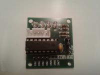
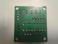
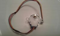
There are two goldpin strips on the board. One four-pin is used to control the motor where we have inputs from IN1 to IN4, the other four-pin is the controller power supply (+,-) and a jumper (the jumper inserted is the motor power supply equal to the controller power supply) on this strip to power the motor where we can take it from the controller`s power supply, which according to the manufacturer should be in the range of 5-12V, or from the outside, but remember that the voltage cannot exceed 50V - higher voltage may damage the ULN2003A system, you also need to pay attention to the current when using a different motor - the maximum current from ULN2003A is 500mA. We can use the higher power supply to power another engine, our tested engine is 28BYJ-48 where the power supply for it should be 5V.
Description of the goldpin power strip - red arrow - plus, black - minus, orange - engine power.
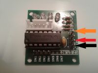
In addition, there are 4 LEDs on the board to visualize what is happening at the outputs of the system. The motor is connected to the controller via the JST-XH-05 connector.
The module works in a very simple way. After applying a high state to the IN1 input, we obtain a low state on the motor connector where the blue wire is connected, this is signaled by the activation of LED A.
Applying a high state to the IN2 input causes a low state to appear on the pink wire, which is signaled by LED B.
Applying a high state to the IN3 input causes a low state to appear on the yellow wire, which is indicated by LED C.
Applying a high state to the IN4 input causes a low state to appear on the orange wire, which is indicated by the LED D.
The red wire is a common connection for all four coils. Here we have the plus from the module power supply through the jumper on the goldpin strip powering our controller.
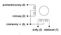
As for the motor, it is a four-phase motor with a power of approx. 0.03 Nm with a step of 11.25 and a gear ratio of 1:64, which means that with e.g. wave or full-periodic control, we have to take 2048 steps to make a full revolution at the gear output.
Now a little theory to know how to use it.
Stepper motors can be divided into unipolar and bipolar. Controlling unipolar stepper motors is easier and less complicated than bipolar motors.
In a stepper motor, the speed does not depend on the value of the supply voltage but on the frequency of steps, and the direction of rotation depends on the sequence of steps.
In this description, I will present how to control a unipolar motor in waves, full steps and half steps.
Wave control.
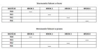
In wave control, also called single-phase control, only one coil is always powered, i.e. only half of the winding from one pair is used in each step. It can be said that with this type of control we use only ¼ of all available motor coils/windings. The control is quite simple, but using it reduces the performance of the engine used.
Full step control.

In full-step control, also called two-phase control, two stepper motor coils are always powered. It should be noted that here we never power two coils from one pair at the same time. This type of control allows us to use our engine more. In this case, two of the four windings are always working, which means we use half of the available motor coils/windings.
Half-step control.

As you can see, half-step control is more complicated than wave and full-step control. This control is a combination of the two previously described controls. In the case of such control, we have a twice shorter step, which gives us greater accuracy, we obtain a smaller effect of engine resonance, which is more visible in wave or full-step control. While in single-phase or two-phase control, where the sequence of control signals is repeated every four ticks, in half-step control it is repeated every 8 ticks. When using half-period control, compared to the controls described earlier, at the same frequency of control signals, the engine speed is twice as slow.
Below is a program written in Bascom by forum member " ~~~pio~~~ ” (who agreed to use it here) where we can test our module with the engine using the types of controls described above. I added a few descriptions to the program so that it could be easily converted to any type of control described here.
Below are videos showing the use of the set and each of the described controls.
Wave control.
Full step control.
Half-step control.


There are two goldpin strips on the board. One four-pin is used to control the motor where we have inputs from IN1 to IN4, the other four-pin is the controller power supply (+,-) and a jumper (the jumper inserted is the motor power supply equal to the controller power supply) on this strip to power the motor where we can take it from the controller`s power supply, which according to the manufacturer should be in the range of 5-12V, or from the outside, but remember that the voltage cannot exceed 50V - higher voltage may damage the ULN2003A system, you also need to pay attention to the current when using a different motor - the maximum current from ULN2003A is 500mA. We can use the higher power supply to power another engine, our tested engine is 28BYJ-48 where the power supply for it should be 5V.
Description of the goldpin power strip - red arrow - plus, black - minus, orange - engine power.

In addition, there are 4 LEDs on the board to visualize what is happening at the outputs of the system. The motor is connected to the controller via the JST-XH-05 connector.
The module works in a very simple way. After applying a high state to the IN1 input, we obtain a low state on the motor connector where the blue wire is connected, this is signaled by the activation of LED A.
Applying a high state to the IN2 input causes a low state to appear on the pink wire, which is signaled by LED B.
Applying a high state to the IN3 input causes a low state to appear on the yellow wire, which is indicated by LED C.
Applying a high state to the IN4 input causes a low state to appear on the orange wire, which is indicated by the LED D.
The red wire is a common connection for all four coils. Here we have the plus from the module power supply through the jumper on the goldpin strip powering our controller.

As for the motor, it is a four-phase motor with a power of approx. 0.03 Nm with a step of 11.25 and a gear ratio of 1:64, which means that with e.g. wave or full-periodic control, we have to take 2048 steps to make a full revolution at the gear output.
Now a little theory to know how to use it.
Stepper motors can be divided into unipolar and bipolar. Controlling unipolar stepper motors is easier and less complicated than bipolar motors.
In a stepper motor, the speed does not depend on the value of the supply voltage but on the frequency of steps, and the direction of rotation depends on the sequence of steps.
In this description, I will present how to control a unipolar motor in waves, full steps and half steps.
Wave control.

In wave control, also called single-phase control, only one coil is always powered, i.e. only half of the winding from one pair is used in each step. It can be said that with this type of control we use only ¼ of all available motor coils/windings. The control is quite simple, but using it reduces the performance of the engine used.
Full step control.

In full-step control, also called two-phase control, two stepper motor coils are always powered. It should be noted that here we never power two coils from one pair at the same time. This type of control allows us to use our engine more. In this case, two of the four windings are always working, which means we use half of the available motor coils/windings.
Half-step control.

As you can see, half-step control is more complicated than wave and full-step control. This control is a combination of the two previously described controls. In the case of such control, we have a twice shorter step, which gives us greater accuracy, we obtain a smaller effect of engine resonance, which is more visible in wave or full-step control. While in single-phase or two-phase control, where the sequence of control signals is repeated every four ticks, in half-step control it is repeated every 8 ticks. When using half-period control, compared to the controls described earlier, at the same frequency of control signals, the engine speed is twice as slow.
Below is a program written in Bascom by forum member " ~~~pio~~~ ” (who agreed to use it here) where we can test our module with the engine using the types of controls described above. I added a few descriptions to the program so that it could be easily converted to any type of control described here.
Code: VB.net
Below are videos showing the use of the set and each of the described controls.
Wave control.
Full step control.
Half-step control.
Cool? Ranking DIY


