Hello again, everyone.
As the postman with the long and impatiently anticipated yellow envelope visited me, today I will try to briefly describe to you here the gadget that was inside - a digital FM radio module made on the NXP TEA5767 chip. This module is.... I would say it's a complete radio, although to get the sound out of it you will need a few extra components.
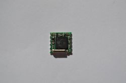
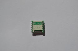
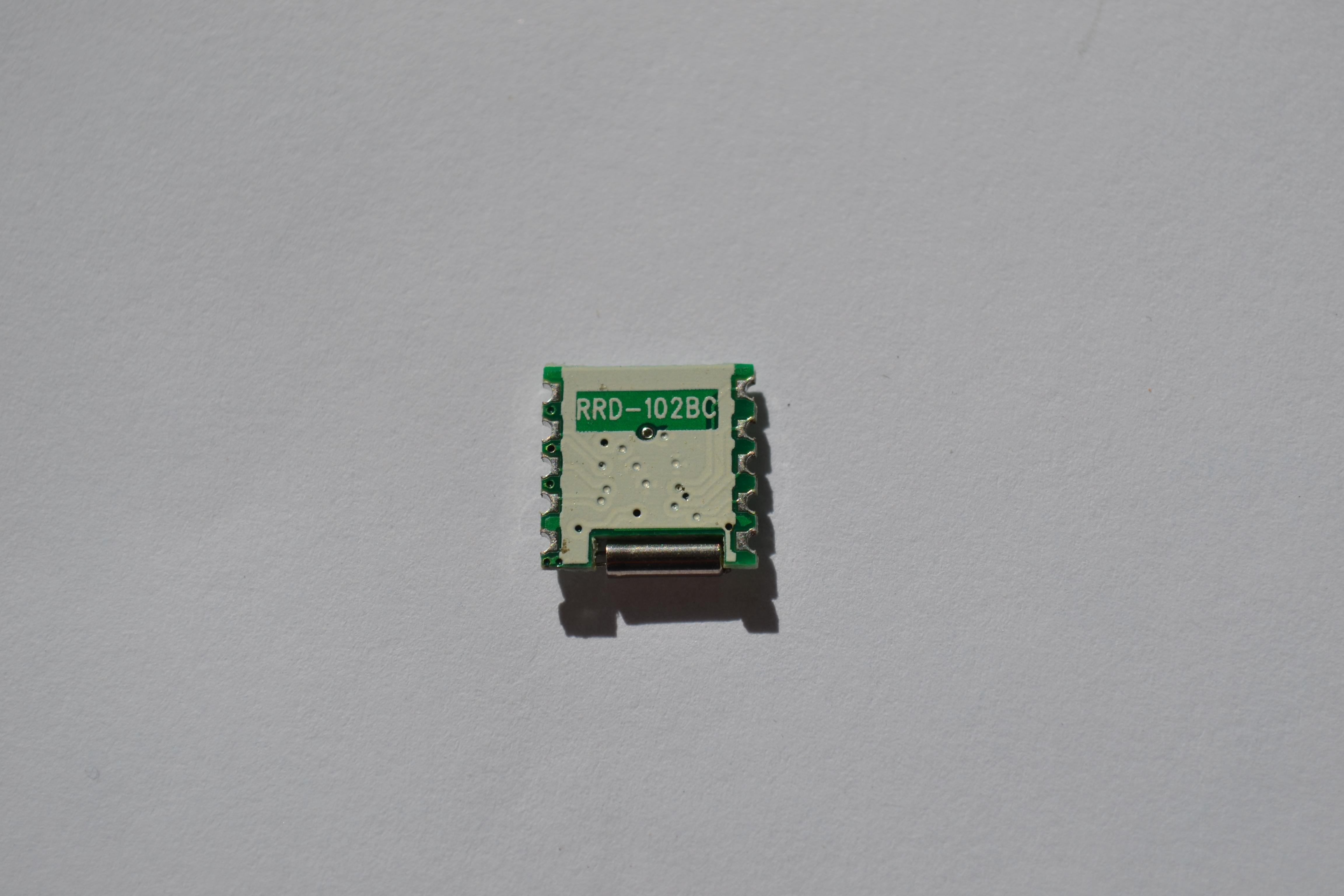
The dimensions of this module are 11x11x2mm - literally a baby, be careful not to lose it while playing with it.

The prices for the module start from $ 0.72 with shipping on Aliexpress, on Allegro you have to pay about PLN 12 with the shipment, although you can find offers several times more expensive - I do not know how they differ from the cheaper ones.
I bought my "receiver" from China and there were no problems with it - "it started from the first arrow".
Thanks to this baby, we can receive radio waves in stereo in the range from 87.5MHz to 108MHz.
The supply voltage is 2.5V to 5VDC. The current consumption after setting the radio station is approx. 13mA when the module is powered from 5V.
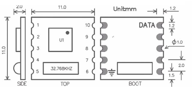
Below is a drawing with the conclusions of our system.
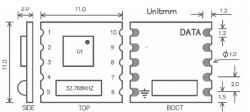
1 - SDA
2 - SCL
3 - BUS MODE
4 - WRITE / WRITE
5 - VCC
6 - GND
7 - Left channel audio output
8 - Left channel audio output
9 - MPXO
10 - antenna
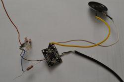
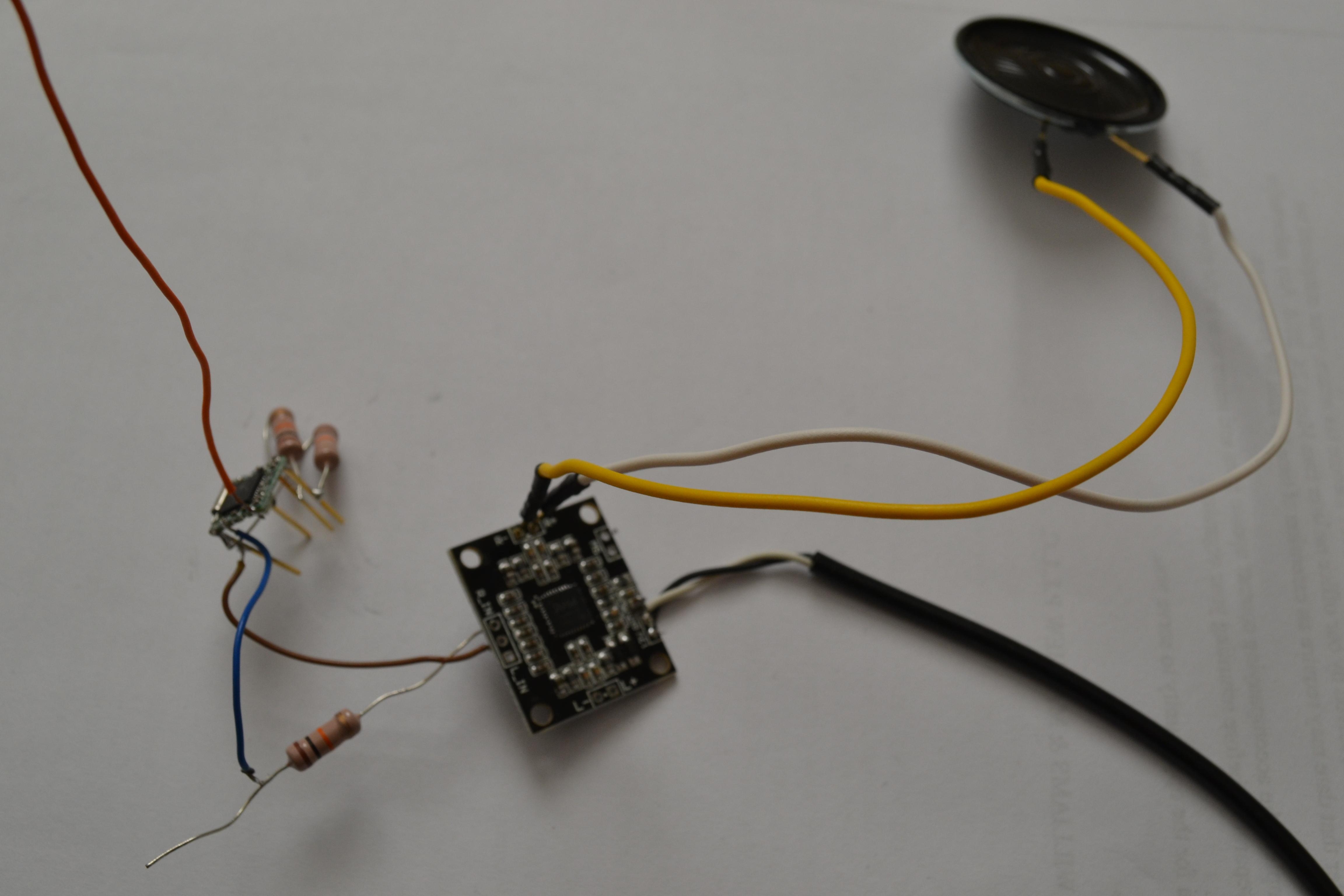
This module is controlled by I2C communication, so we will need some microprocessor to set up our favorite station. In addition, the audio output is so weak that it will not "pull" even the headphones, so you will need an amplifier. I used a small, cheap, ready-made class D amplifier based on the PAM8610 chip - I wrote a small one, but comparing it to the radio module, it cannot be said that it is small. We will need two more resistors (I used 10k, you can also give 4.7k) to pull up the SDA and SCL communication lines to the plus - basically all that is needed except for a power source, a few wires and a loudspeaker.
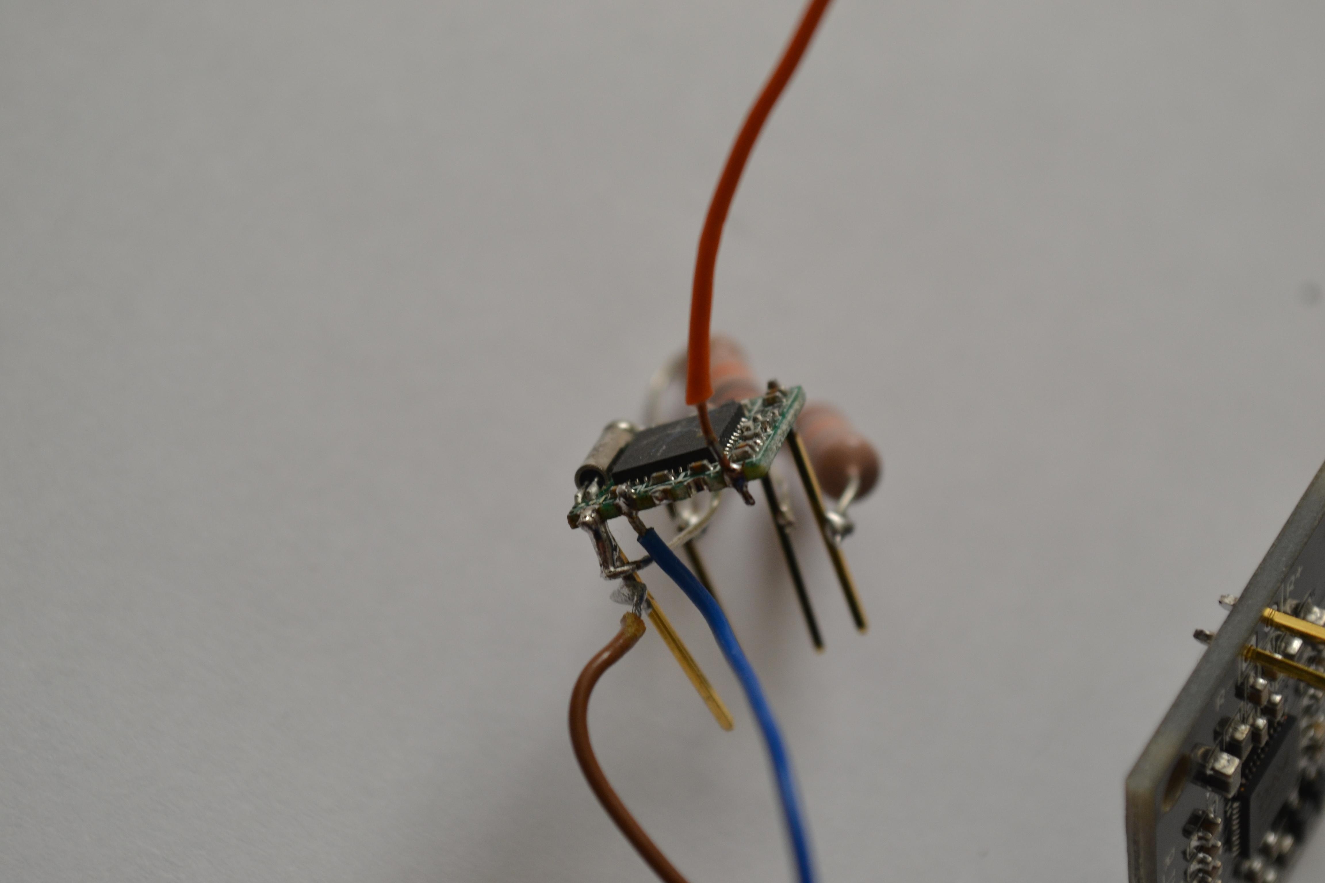
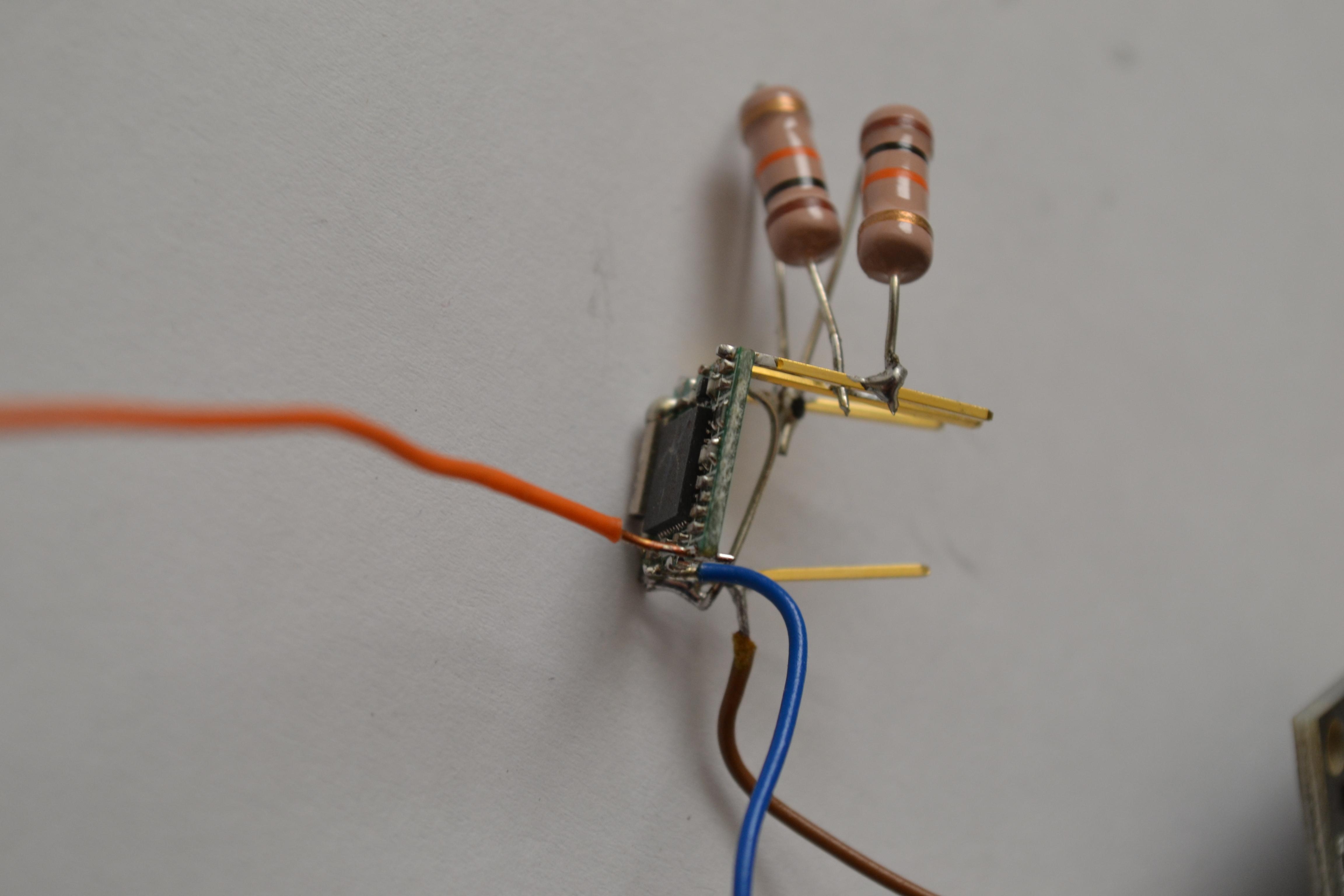
Below is a picture of what it should look like.
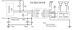
BUS MODE is connected to ground so that communication via I2C works.
As the module is really small and its raster is not standard, only 2mm, so it had to be dealt with somehow, and a "hybrid" as shown in the pictures below came out. :)

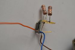
It's about testing the module, not aesthetics, so forgive me - I did it on McaGyver and it's important that it works, next time I will try harder so that apart from the ears and eyes they can enjoy.

To control the radio, I used the ZL2AVR development kit, although a breadboard and a microprocessor that will send a few bytes using I2C - for example AVR or PIC or the popular Arduino is enough here.
Ok, we already know how to connect our module, so let's move on to the description of how to order the radio to "play" the frequency of our choice.
We need to send 5 bytes to our radio, and before that send the address of our radio receiver.
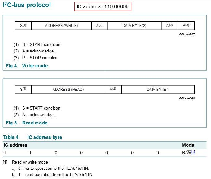
Of course, documentation can help.
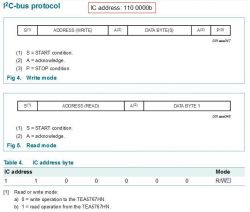
According to the documentation, the address of our radio is: 110,000b
The module can operate in two different operating modes - read and write, which must be entered in the address.
0 - write mode
1 - reading mode
Hence, we will use the address & B1100 0000 (in binary or & HC0 in hexadecimal), because we choose the write mode.
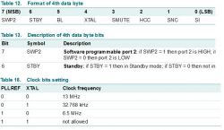
Excerpt from documentation for address description:
Next, 5 bytes should be sent, the description of which can be found in the documentation.
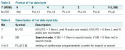
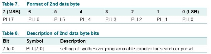
In the first two bytes we give the frequency of our radio station - PLL, it is 14 bits.
Fragment of documentation for description of the first two bytes for write mode:
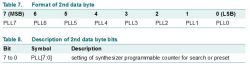
PLL can be calculated from the formula:
where RMF is the frequency of our station in MHz.
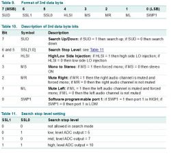
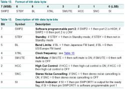
Take into account that in the denominator we have the frequency of the quartz that is in this module. Using the TEA5767 chip itself, you can use a different quartz there, but its value must be taken into account in this formula and taken into account in the settings for the fourth and fifth bytes - these are XTAL bits in the fourth byte and PLLREF in the fifth byte.
For example, for the station frequency of 98MHz and the quartz 32.768kHz, which is used in this module, the formula will give us 11990.3564453125, of which PLL is the integer part of this number, i.e. PLL = 11990, which gives us 10111011010110 in binary notation.
The first byte in this case is: MUTE SM PLL13-PLL8, where the MUTE bit is set to 0 and the SM bit also to 0, which gives us a complete byte in the form & B00101110.
The second byte is PLL7-PLL0, which is & B11010110
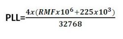
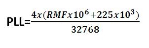
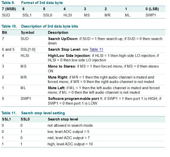
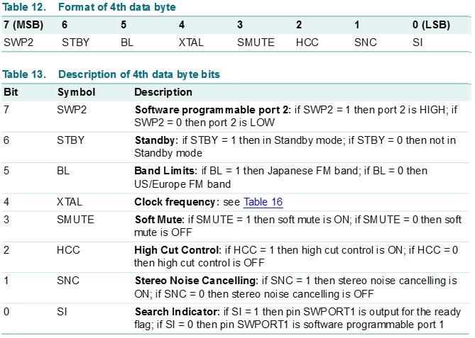
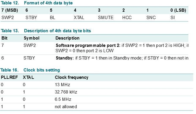
The next bytes are settings that I will not describe here - we have them described in the documentation.
Fragment of documentation for description of the next three bytes for write mode:
I am sending here & B00010000 as byte 3
& B00010000 as byte 4
& B00000000 as bit 5
So to bring out the sound of our selected radio station (example 98MHz), we send in turn:
& B11000000 or & HC0 - binary or hexadecimal notation
& B00101110 or & H2E
& B11010110 or & HD6
& B00010000 or & H10
& B00010000 or & H10
& B00000000 or & H0
At the beginning of my game, I sent this data to the module every 100ms - I suggest not to do it, because it introduces some disturbances in the radio's operation. This causes the sound to be interrupted for a fraction of a second - as if you were pressing a button on the TV remote control every now and then to select the same channel.
Below is the code written in Basom for ATmega8 to operate this radio. It takes up about 25% of the memory, after resigning from calculating bytes by the program, and entering them permanently, we can go down to 6% of the memory, but I do not know if it will be possible to run it on ATtiny13 due to the lack of hardware I2C.
For the less initiated, I will explain where the following part came from, because I wrote about sending the address and five bytes, and you can see that I only send the address and three bytes.
As the settings for each station in the last three bytes are identical, these bytes written into the program are permanent. The first two change depending on the selected frequency and in order not to do it yourself - to simplify it, the program is written in such a way that it is enough to enter the selected frequency in the PLL variable, and the program itself will calculate the first two bytes to be sent. If we want to enter our frequencies into the program, we enter the frequency in MHz in the PLL variable, and the program will calculate the first two bytes by itself.
When starting this little radio it was without problems - the loudspeaker made a sound right after loading the program to the processor and pressing the button. The biggest problem in all this was only soldering this "hybrid", but I think it will not be a problem to use Google to find a library, eg in Eagle for this baby.
As you can see from the photos - I used a piece of wire about 10cm long as the antenna and as you can hear on the attached recordings - the radio sounds quite good
The radio has an automatic station search function with the option of setting its sensitivity - 3 sensitivity levels. I didn't have much time to thoroughly test it. I think it would be helpful to read the current frequency from the radio here, because during the automatic search, the radio stopped at what it thought was a radio station, and I was not able to get information about the frequency, which caused me to wander in the dark in a maze of various kinds noise and silence, where sometimes we managed to find stations but not occupy their frequencies.
Perhaps someone will share the knowledge about reading information from this module here - I could not get any information from the module in read mode, maybe I am doing it incorrectly.
In the attachments the documentation for the described radio module and two recordings of the sound it produces, so that you can judge for yourself whether you can expect something nice from the module for less than a dollar, or you can only be disappointed, as is usually the case with Chinese gadgets.
I hope that this description will encourage you to play with this radio module and describe your struggles and achievements here, which will expand this topic and help others get to know this baby.
Below is a link to the next part describing the TEA5767 module
https://www.elektroda.pl/rtvforum/topic3451947.html#17161950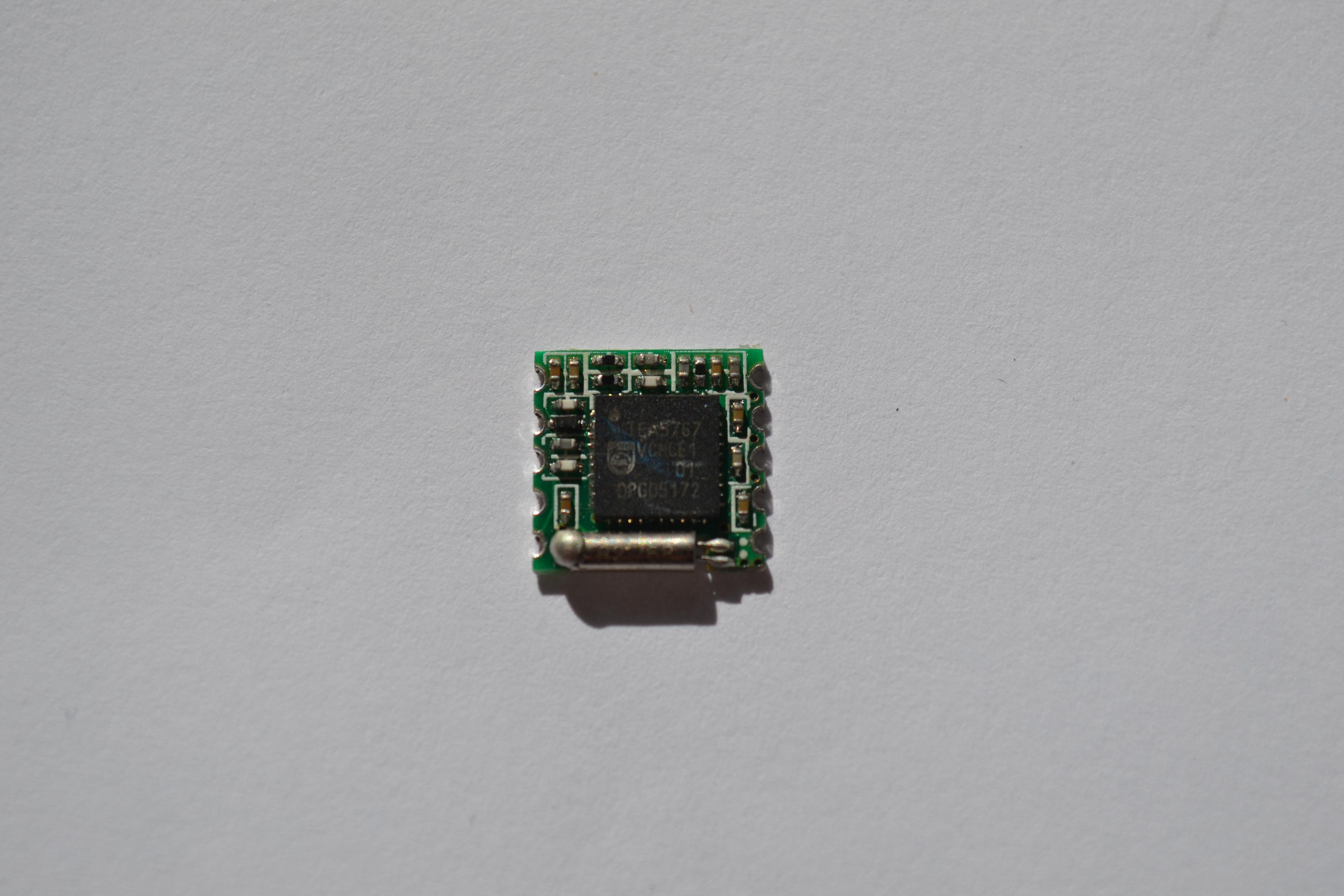


Comments
Hello, it is hard to deduce anything more from the recordings about the quality of the received signal, but what are the "feelings" from the listening session? [Read more]
I am not an audiophile or a fan of listening to music so that others would also have to listen to it, but for me it sounds reasonably well. There is no revelation on this amplifier and loudspeaker, because... [Read more]
As you mentioned, there are no problems with the quality of the received signal even with 10cm of wire in the car ?? [Read more]
For some time I have been looking for a small radio module, not only a small one, and even a small one. For this code in BASCOM. In a word, I have everything I was looking for :) Thanks a lot for a great... [Read more]
Many market radios have an FM module on this cube. As long as the local toto transmitter catches, you can forget about clean reception, e.g. during the route where the transmitters are several dozen kilometers... [Read more]
Well, sorry that it will attach, but I already thought that a nice module for DAB +, and here an ordinary analog FM ... i.e. an analog radio module, not a digital one. Digital here is the control and that's... [Read more]
I will share my experiences with the use of this type of modules. I started with this TDA 5767. At my pickup location it's terrible. The module was properly receiving up to approx. 95 MHz. He couldn't... [Read more]
I confirm that I have been using SI4703 for 5 years, because then it cost ~ PLN 50 and received very good on a 5 cm cable, it is worth mentioning that it has RDS :) [Read more]
For comparison - this is how a similar module sounds with the RDA5807M chip, where apart from the IC there is only 32kHz watch quartz and power blocking capacitors: I recorded the sound through the... [Read more]
There are much more interesting modules: https://www.hamshop.cz/avr-arduino-raspberry-pi-c16/modul-vhf-transceiveru-134174mhz-1w-dra818v-i266/ https://hackaday.io/project/6749-hamshield-vhfuhf-tra... [Read more]
Certainly more interesting, but they are used for something completely different than receiving public FM radio ... [Read more]
The module with the Quintic QN8025 chip was very nice, but I have not been able to track it for a long time (basically it is only on Aliexpress, it went up a lot). The audio quality was quite good, the... [Read more]
Report: [Read more]
I don't know how to respond to the report. Grala1 presented the module and showed how it can be quickly launched. Did my mention of other similar modules hurt anyone? I stated a fact. After that,... [Read more]
Gentlemen, in relation to the topic, I have a question for you. I am slowly picking up the car player instead of the factory navi and I was thinking about using TEA5767 as an FM receiver in combination... [Read more]
I am looking for something to build a receiver for myself and I am confused. Here is a similar thread and other conclusions: https://www.elektroda.pl/rtvforum/topic3124385.html Could anyone else share... [Read more]