Rotary encoder - pulser - is an excellent input device for controlling e.g. menus in the device interface. In the following tutorial, we will describe how to use a typical pulser in conjunction with the Arduino module.
Step 1. Watch the movie If you do not want to read the entire text below, and the English language is not a problem for you, watch the video below - it will certainly help you understand how to connect the pulser and program the Arduino so that the whole thing works together.
Step 2. Introduction Such an encoder is an electromechanical device that translates the angular position or rotation of an axis into a digital or analog output signal. There are two types of rotary encoders:
1) Absolute - The output state of this encoder corresponds exactly to the absolute position of the axis. Thus it is an angle converter.
2) Incremental - the signals at the output of this encoder correspond to the axis movements, so the position calculated on their basis is relative. Processing these signals into data on position, rotational speed, etc. is always carried out remotely.
Step 3. What is an incremental rotary encoder The incremental encoder gives information about changing the position and its direction (clockwise and counterclockwise rotation). In many applications this functionality is essential, however, this element does not track the absolute position. Therefore, in some encoder applications, it may be necessary to initialize the encoder by moving it to a known, fixed position.
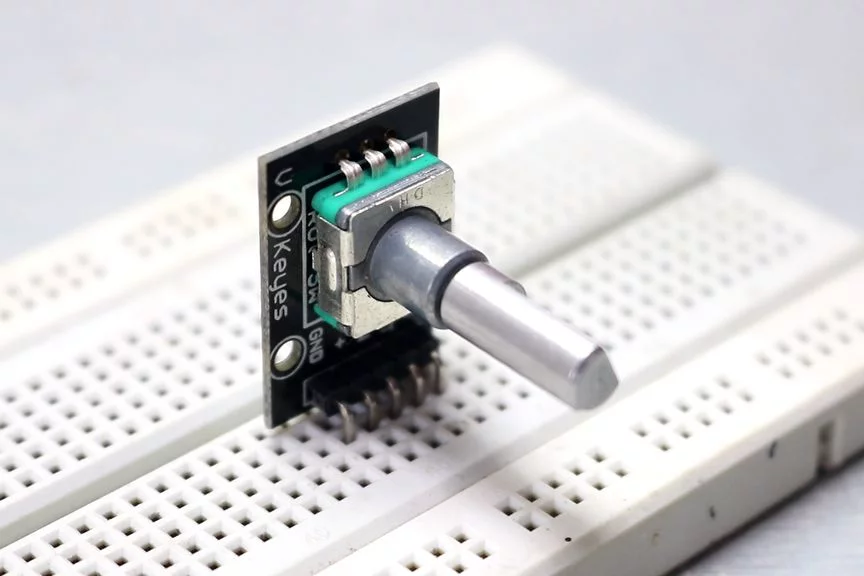
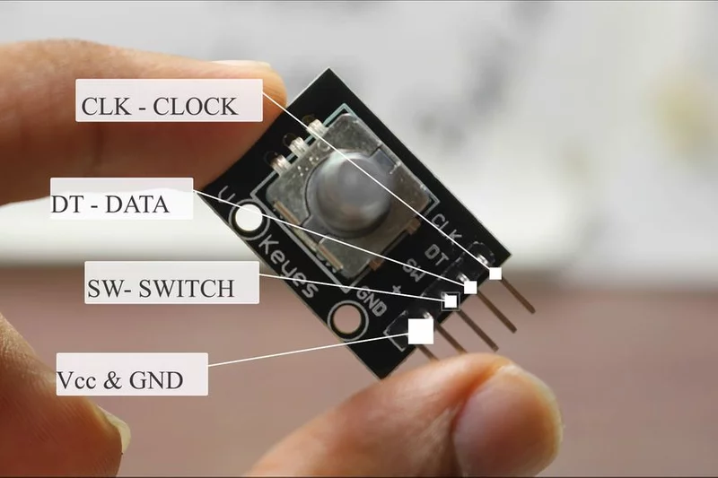
Step 4. Construction and principle of operation An exemplary encoder that we will use in the tutorial has all the necessary resistors that pull the I / O lines. This element has five output pins:
Clock, Data, Switch, Vcc, GND.
Construction The knob we turn is internally connected to the disk inside the encoder. It will move clockwise or counterclockwise, just like the knob that the user turns. On the surface of this disk there are fields connected to the power line. The remainder of the disk is at ground potential. Above the disk there are two contacts shifted relative to each other by a certain distance - these are the outputs of the Clock and Data.
Principle of operation When we turn the encoder, the state of the outputs will change with the position of the disk in the encoder. In such a situation, we can observe sequences of impulses on the Clock and Data outputs.
If we look at these impulses, we can see that they are out of phase by 90 degrees. If the encoder turns clockwise, the clock output pulses will be first, and if the encoder turns counter-clockwise, the first pulse will be shown at the data output.
By analyzing the state change on these two outputs, you can immediately judge which direction the encoder knob is turning. Now let's try to implement this analysis programmatically in Arduino.
Step 5. Software Example 1: (Counter.ino)
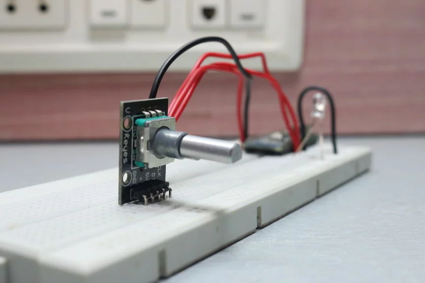
In this example the clock pin is connected to pin 3 and the data pin is connected to pin 4. We have connected a switch to pin 5 which activates when we press the encoder.
In the above program, we first defined a series of variables and set the pins to which the encoder was connected as input pins. Finally, a serial port was launched, which we will use for communication and data transmission.
Then the main program loop is started. This is where we read the state of the encoder inputs. The current state is written to the variable state. If state! = State in any iteration, it means the encoder has turned. Then if data! = State it means the encoder turned clockwise and vice versa if the variables are equal. These encoder pulses will increment and decrement the counter accordingly.
The current counter value is then transferred via the serial interface. If the button is pressed, the counter will be reset and the new value will also be sent via the serial port.
At the end of the loop, the new state is written to the variable state and the cycle can start all over again.
Example 2: (LEDBrightness.ino)
In this case, being a modification of the first program, the counter value is used to control the brightness of the LED via PWM. The counter value is directed to the analogWrite function instead of the UART interface. You should only limit the value of the counter to a value from 0 to 255, because such values are taken by the variable controlling the PWM filling.
And that's all you need to easily handle the rotary encoder - the pulser in our device. Do you use such an element in your projects? Show off your implementations and devices, not necessarily based on Arduino modules.
Source:
https://www.instructables.com/id/How-to-Use-an-Rotary-Encoder-With-Arduino/ 

Comments
I used the pulser several times. A graceful device. Small, and several functions can be realized on it. I only use the rotary.h library [Read more]
With the encoder, the interrupt reading definitely stops, with the extended code in the polling mode (as above) it simply stops working. Greetings [Read more]
The examples from the first post should be moved to the "How not to write programs" section. The program will work relatively correctly at a low uC clock frequency (no elimination of contact tremors) or... [Read more]
Incremental encoder, this is an incremental encoder in Polish, what did everyone insist on this encoder type? The original text is written in Polish as the teacher speaks English ;) , besides, there... [Read more]
remote controller -> remote. - The manipulator's clap - ??? - Male overhang - ??? - Night overhang - ??? [Read more]
Double clap, it's probably only with Jan Bielecki ;) Let us take care of our native language where possible. "- Male overhang - ??? - Night overhang - ??? "- commercial dictionary? (Aerator... [Read more]
These algorithms from the article, unfortunately, are bad and would turn out to be a fraction of what's below ... In my project in C on Atmega32 clocked at 16MHz as of today (because the project is... [Read more]
I have been using the library from Sylwek for a long time, of course the old one, probably one of the first versions. This is a great piece of code. I also use STM, because why not :) I used to try to... [Read more]
Encoder read only by pooling. For the simple reason that it is deterministic. In the case of vibrating contacts on the interrupts, you suddenly get 10x this frequency of calling the function. I have... [Read more]
@ grafan999, nothing more to add :) [Read more]
This algorithm waits for only one pulser output to be changed ("Clock"). Analyzing both outputs would double the resolution, only then the algorithm would get complicated. [Read more]
Useful article, thank you :) [Read more]
Amateurs (Aduinists) think so. They don't know what a timer is. [Read more]
Can you develop a thought? I am not an Arduiner, I use timer interrupts for reading, not external interrupts, so I do not understand your remark too much. [Read more]
In professional devices, a preliminary filter is often used to remove the effects of vibration of the rotary encoder contacts, e.g. something like this: https://obrazki.elektroda.pl/3951185100_1532534740_thumb.jpeg... [Read more]
Any system with capacitors at the encoder is lost at the start for me, because it limits the speed of its reading. Maybe in less demanding applications it works well, but certainly not in PROFESSIONAL... [Read more]
In particular, there are 40 encoders in the device (for setting various parameters) as in the digital console from which this chip comes. This is not for drives, but for manually rotated encoders. ;) [Read more]
Nevertheless, handling with capacitors, where the software part is usually neglected, irritates me, because it is enough to wear the encoder a little or a little dirt (which increases the vibrations of... [Read more]
Well, do something for the world and show off this algorithm :) [Read more]