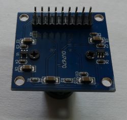
Using the camera module
OV7670 we can process an image with a resolution of 640x480 in our project. The VGA resolution may seem ridiculously small these days, but at a low cost, we can enrich our project with the possibility of processing the image from the camera. The mentioned 640x480 resolution for e.g. an Arduino nano module may turn out to be surprisingly large compared to the resources of the microcontroller. Knowledge from experiments with a low resolution camera may be useful when trying to use more expensive modules with higher resolution. In the case of newer camera modules, it is worth taking a look at the project
ArduCAM .
I tried to wade through configuring the registers, but I must admit that this task beat me temporarily. The number of dependencies between the registers is large, the descriptions of some options are quite enigmatic. Working with registers is a good field for experimentation and you can get a lot out of the camera module, but it takes time. I was able to confirm the operation of the following registers:
- Writing the value 0x80 to the address 0x12 resets the values in the registers to default.
-Register 0x0C enables image scaling (bit 3), while saving appropriate values to register 0x12 enables setting QCIF, CIF, VGA resolution and enabling data transfer mode for consecutive pixels as RGB (eg RGB565). The camera can send data in the YUV / YCbCr (4: 2: 2) format where the next bytes are not the 1: 1 values of consecutive pixels
link (as it is e.g. in RGB mode).
- Writing the value 0x20 to the register 0x15 will generate a PCLK signal only when pixel data is sent.
-Registers 0x11 and 0x6B allow you to set dividers and PLL for the clock signal.
-Register 0x1B allows you to introduce delays in sending data, which can sometimes be useful when processing data
Since I was overcome by the manual configuration of registers, I used the ready-made code:
https://github.com/indrekluuk/LiveOV7670 which allows you to display the camera image on the 128x160 TFT SPI display.
Live view from OV7670 on TFT 128x128 ILI9163. In the video below, the effect of the live view from the camera, which allowed to confirm the correct operation of the camera module, and to set the focus of the lens:
[movie: 8a8eacdd2e]
https://filmy.elektroda.pl/6_1534532529.mp4 [/ movie: 8a8eacdd2e]
The module uses a large number of signal lines, if the data about the image were transferred, for example, via the SPI serial bus, the number of lines used would be smaller, while the hardware SPI support may facilitate data download.
Commissioning as described by the author:
- download files from github
-copy "src / lib / LiveOV7670Library" and "src / lib / Adafruit_GFX_Library" to the Arduino folder "libraries"
-open "src / LiveOV7670 / LiveOV7670.ino" in Arduino IDE and compile and upload to Arduino board
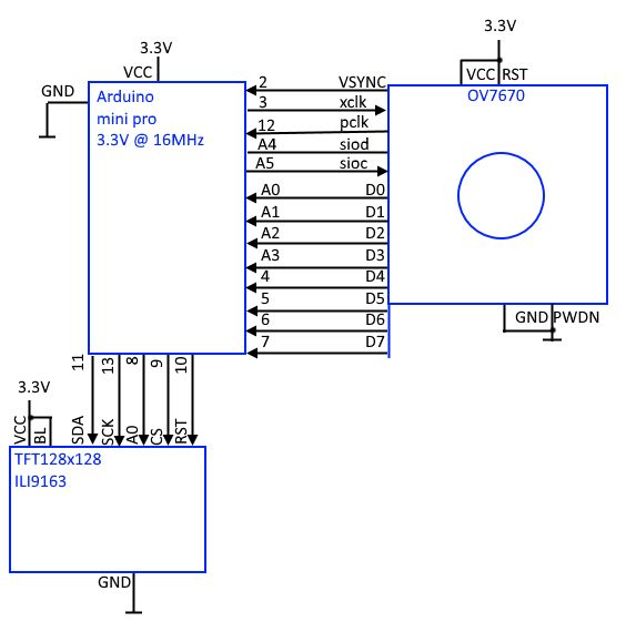
To avoid the use of logic level converters, I used an Arduino mini pro with a 16MHz resonator, but powered by 3.3V. According to the ATmega328 note, the microcontroller at 3.3V should not be clocked at 16MHz (e.g. it should be the Arduino mini pro 3.3V 8MHz version), but for the purposes of the test such a set simplified the connections and worked properly.
The author used a 128x160 TFT display, during the tests I connected a 128x128 TFT display with the IL9163 controller.
Red and blue have been changed in the projected image. For testing purposes, checking if the camera module is working, and focusing - swapped colors are not a problem. If you want to get the right colors by changing the order from RGB to BRG, you can, for example, quickly change the value in the MADCTL register in the Adafruit_ST7735_mod.cpp file:
on
According to
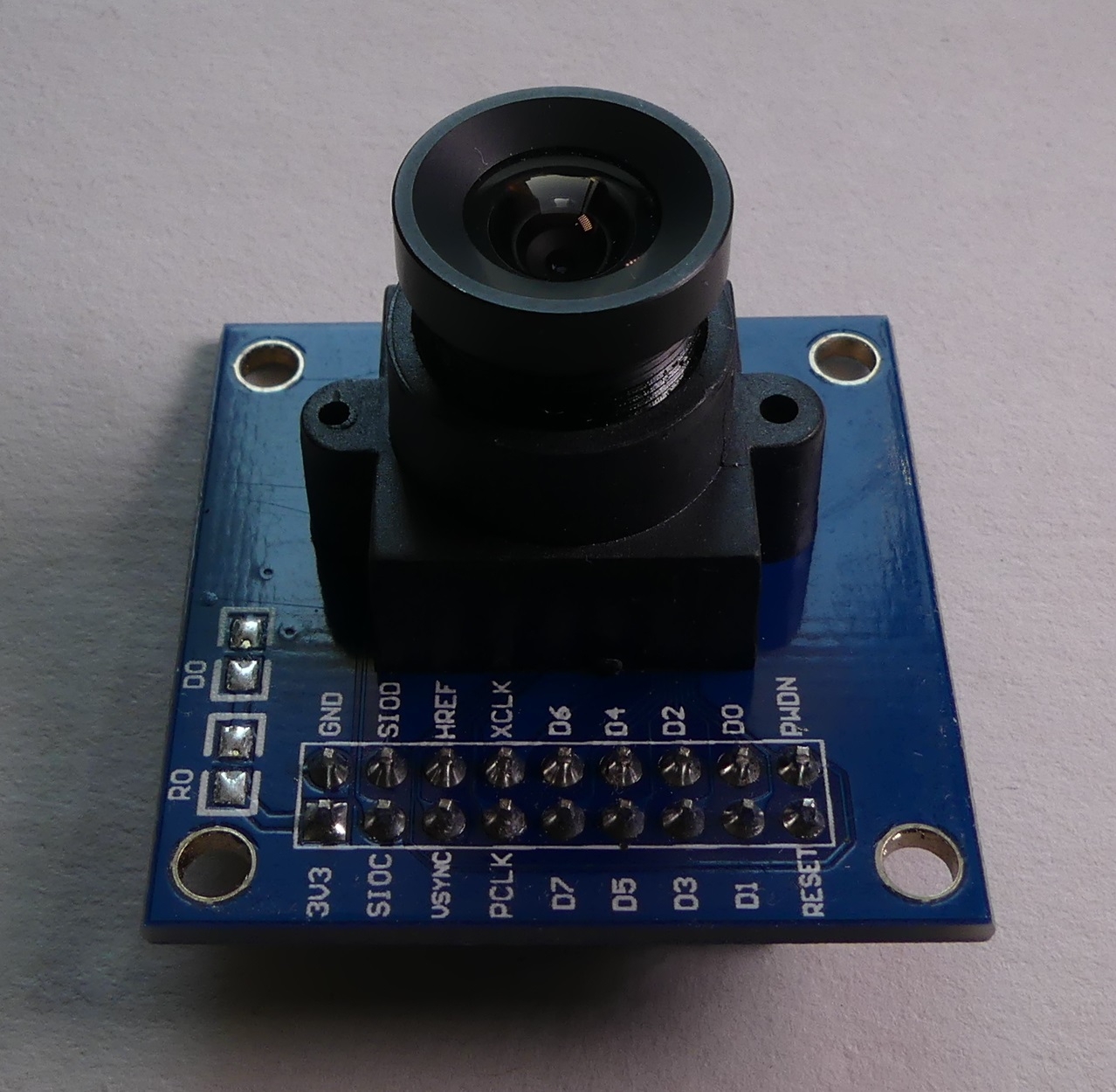
OV7670 camera documentation the module is powered by 3.3V, when connecting to Arduino 5V, take care of the conversion of voltage levels. The module has SIO_C, SIO_D pins, which are an SCCB bus with operation similar to I2C, a serial bus used in the camera configuration. The module responds to the I2C bus at the address 0x21. Inputs RESET (high state, camera operation) and PWDOWN (low state, normal operation). XCLK clock signal input and PCLK output for synchronous data download from the parallel 8-bit D7-D0 bus. HREF and VSYNC outputs synchronizing data download from the parallel bus (the appropriate configuration allows to resign from the HREF signal - line signal, using only VSYNC - frame synchronization).
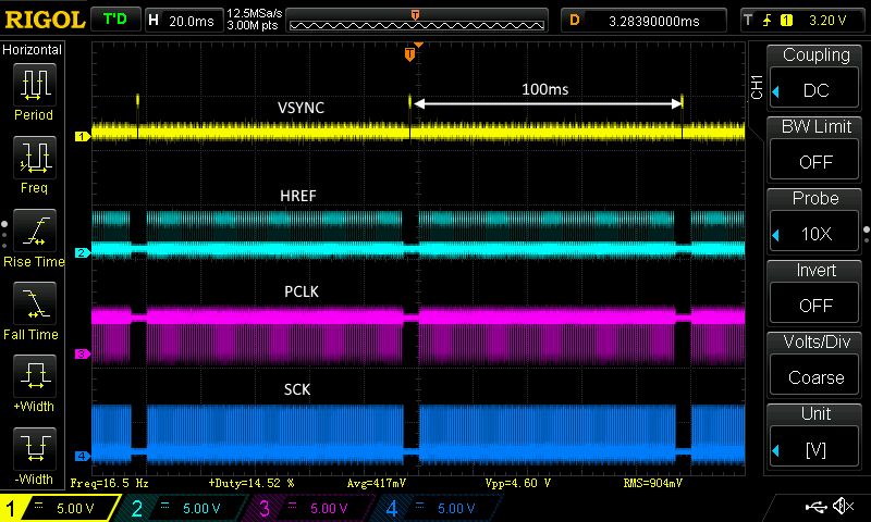
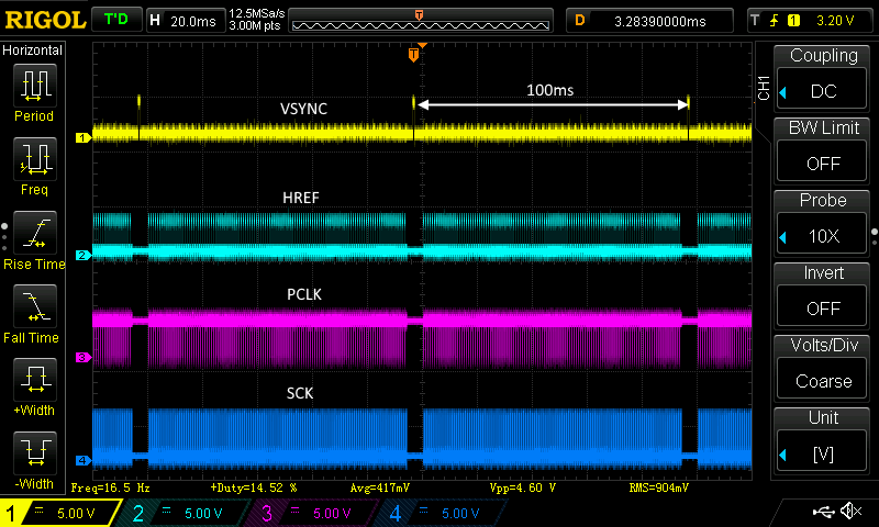
The basis for starting the module is the appropriate configuration of registers via the SCCB bus. SCCB interface lines should be pulled up to + power supply with resistors 4.7-10kom. It is important that the camera module has a stable 3.3V power supply. For the bus to work properly, give a clock signal to the XCLK input, according to of the application note, the frequency of the input signal should be 10-48MHz (I checked experimentally that with the input frequency at XCLK = 4MHz the SCCB interface responds correctly). The code under test generated the clock frequency XCLK = 8MHz. The frequency of the PCLK signal clocking the data changes on the D7-D0 lines (data should be read on the rising edge) depends on the set dividers and PLL. In the case of the tested code, we get a clock with a frequency of 2MHz on PCLK.
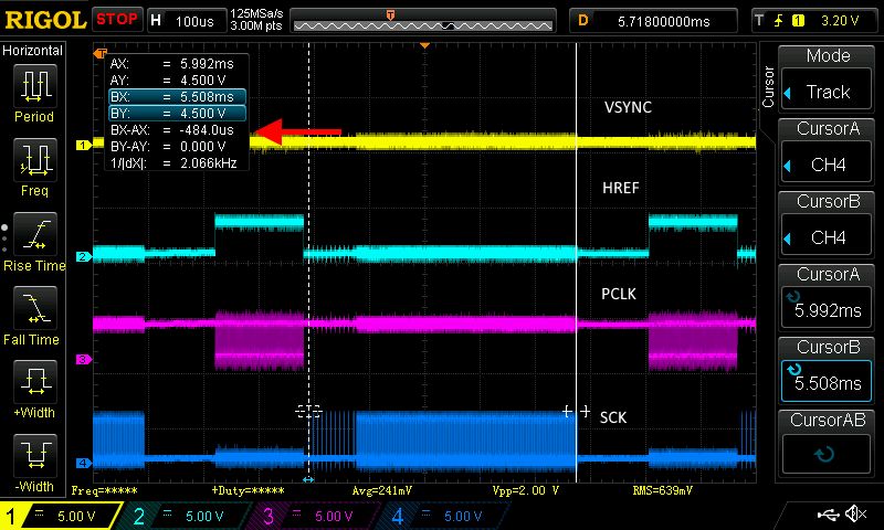
The time interval between VSYNC pulses (interval between frames) is 100ms, i.e. we have ~ 10FPS:
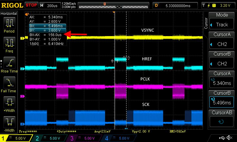
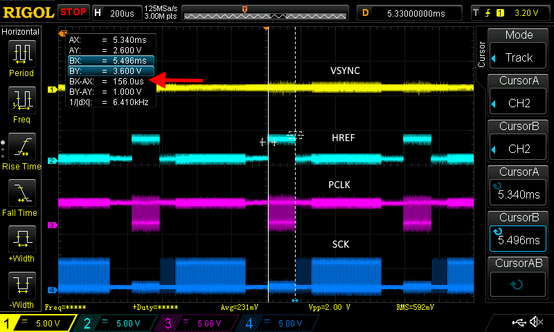
The interval between HREF pulses (one line) is about 800us:
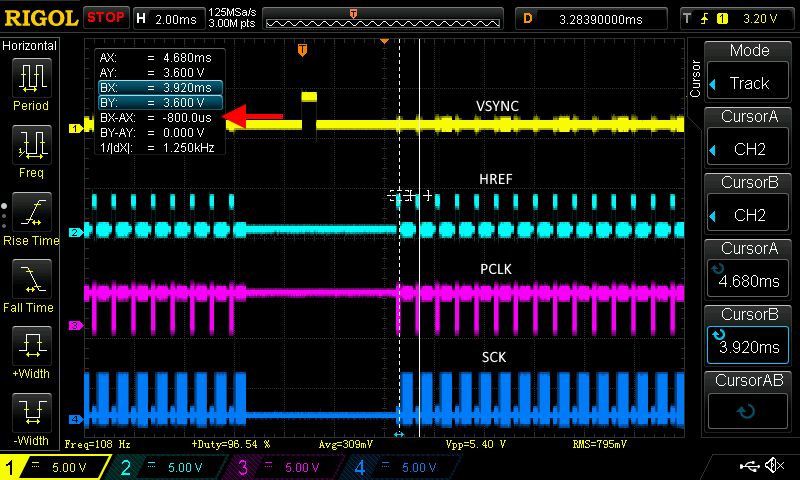
The transmission time of one line from OV7670 is ~ 156us, the transmission is accompanied by a high state on the HREF line and a clock signal on the PCLK line:
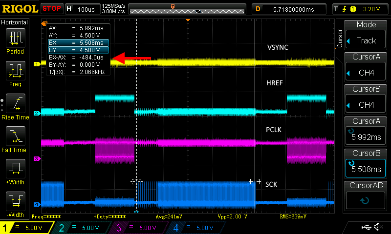
Between successive transmissions of the OV7670 line, the data is sent to the TFT display via the SPI bus, accompanied by a clock signal on the SCK line, the transmission lasts ~ 484us:
Self displaythe image from the camera on the display is not practical, unless we send digital data over a longer distance via wired or wireless transmission. A more interesting application would be to save data from the camera module to an SD card, obtaining a wildlife camera or a timelaps camera, e.g. for nature observation. The resolution of files recorded by such a camera will be quite hopeless, but the whole thing would be quite cheap and would have an experimental value.
Saving the image from OV7670 on the SD card On page
link we will find an idea for a way to save the data from the camera to the SD card. It turns out that the author chose a resolution of 320x240 lower than the maximum 640x480. In addition, he chose the format of reading data from the YUV camera and saves only luminance data to the card, which will result in a black and white image. Finally, to get the BMP file, the files are processed with python script. Not very effective and convenient, why is it difficult to save a color (RGB565) BMP file on an SD card? Well, data writing to the TFT display was sequential and did not require confirmations and additional operations, while the SD card supports the file system. The inefficient Arduino library supporting SD cards and the variable behavior of the SD card make it difficult to quickly and sequentially write data from the camera to a file on the card. Resolution limitation from 640x480 to 320x240 results from the remaining memory for variables after importing the SD card library. One 320px line fits in the remaining memory, while with 640px 16b color is already a problem.
Summary The OV7670 module is cheap and allows a lot of experimentation with image reading and processing. The considerable limitations of the module may discourage less persistent people. You can try to build cheap, simple, small devices for timelaps / wildlife camera experiments. To freely experiment with the processing of camera data, you can choose:
-a platform that has enough RAM to fit the entire frame with the image (or in the economy version - a single line)
- camera module with a FIFO memory buffer to which image data will be written, while the reading can be performed at any speed
- camera module sending image data via serial bus (fewer connecting cables)
-module with good documentation, libraries / api / examples to configure, so as not to struggle with getting the first frame of the camera image
-a platform with fast interfaces and computing resources to process data quickly
Low-level experiments with VGA 640x480 image capture attempts to appreciate cameras and camcorders built into our smartphones, as well as standalone 4K cameras and camcorders


Comments
I used to test the OV7670 with ATMega8A, which only served to drive a new LCD frame on the SSD1963 driver and to start the webcam. It was flying elegantly with a maximum resolution of 640x480, there were... [Read more]
@Mscichu if you want and time, feel free to present your achievements in DIY or Articles. What PCLK clock did you use with OV7670 + SSD1963 in 640x480 mode? In OV2640 I see a disturbingly similar... [Read more]
As for the OV7670 project, it's an old project and I have only scraps. From the diagram of one of the first versions, I can see that on the XCLK I had an input from an external generator and I ordered... [Read more]
Interesting experiments. So for ESP32 streaming, "raw" frames are read from OV2640, and then compressed and sent over TCP? When OV2640 sends a compressed frame, does it send some end of data stamp?... [Read more]
You can pick up as RAW or already compressed, but you can quickly choose the compression quality yourself. The camera always changes the signal to VSYNC after the finished frame, whether it is RAW or JPEG,... [Read more]
Smart with this use of VSYNC to inform about the end of compressed jpg data. I understand that in this case HREF does not carry any information? What is able to play this "movie" as a saved refresh page? ... [Read more]
I played what I had on the computer, it was probably VLC or the beak. I will try to record something tomorrow and check exactly what and how. As for the information about the end of JPEG, I can see in... [Read more]
It took me a while to get everything together (especially to find a working ESP program). After programming ESP32 in the command line, we get a message about the correct activation of the camera and... [Read more]
A very interesting effect with the use of cheap components. When organizing and expanding, the material can be easily placed as a separate article or a DIY project. [Read more]
ESP32 is generally a very interesting product. Quite recently, I started running as an MP3 decoder. The library itself works as an internet radio player but can be run to play from an external SD card.... [Read more]
Writing is a matter of practice, you can learn a lot from the comments, as is the case with this material. I tested internet radio on ESP32 , without an external DAC, the effect is average, but at... [Read more]
In my opinion, ESP8266 is suitable for simple things in serial productions because it is still cheaper than ESP32, so there is no point in overpaying when controlling e.g. a relay. For a hobbyist, it is... [Read more]
Hello. I'll refresh the topic. A few years ago I used a 640x480 resolution camera to directly drive a display with the same resolution. Like my colleague Mscichu, I built a chip that converted 8-bit... [Read more]
Projects for the OV2640 camera are ready on ESP32. Streaming via ESP to some LCD will be fine, but from what I saw it lags. It's better to connect ESP to wifi and have a preview on the phone. You can... [Read more]
Yes, that's right. I was interested in these modules. The point is that, as you have noticed, it is very lazy, and with what I achieved a few years ago (a similar solution to yours) it is a tragedy.... [Read more]
At the moment I will not help with the work, but I can give you some hints. The OV2640 camera can be controlled like the OV7670, i.e. with an RGB565 output. The processor, e.g. ESP, can only listen on... [Read more]
Thanks for the hint, but I would like to use a camera with Pixelplus POA030R for this project, because I have several dozen of them. I also have an older version of the PPV401C with the PO6030K system... [Read more]
For the last few hours I have had doubtful pleasure with the OV7670 module and I have completely given up. The situation is that I am rushing the module with a 16MHz clock. I set I2CWrite (0x42, 0x11,... [Read more]
Również pokonało mnie konfigurowanie rejestrów w OV7670 i wykorzystałem https://github.com/indrekluuk/LiveOV7670 COM7 0x12 domyślnie 0x00 http://embeddedprogrammer.blogspot.com/2012/07/hacking-ov7670-camera-module-sccb-cheat.html Bit[7]: 0:... [Read more]