logo elektroda
logo elektroda
X
logo elektroda

OV7670 camera module, commissioning, tests with Arduino

TechEkspert 14109 25
ADVERTISEMENT
Treść została przetłumaczona polish » english Zobacz oryginalną wersję tematu
  • OV7670 camera module, commissioning, tests with Arduino
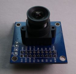
    Using the camera module OV7670 we can process an image with a resolution of 640x480 in our project. The VGA resolution may seem ridiculously small these days, but at a low cost, we can enrich our project with the possibility of processing the image from the camera. The mentioned 640x480 resolution for e.g. an Arduino nano module may turn out to be surprisingly large compared to the resources of the microcontroller. Knowledge from experiments with a low resolution camera may be useful when trying to use more expensive modules with higher resolution. In the case of newer camera modules, it is worth taking a look at the project ArduCAM .

    I tried to wade through configuring the registers, but I must admit that this task beat me temporarily. The number of dependencies between the registers is large, the descriptions of some options are quite enigmatic. Working with registers is a good field for experimentation and you can get a lot out of the camera module, but it takes time. I was able to confirm the operation of the following registers:
    - Writing the value 0x80 to the address 0x12 resets the values in the registers to default.
    -Register 0x0C enables image scaling (bit 3), while saving appropriate values to register 0x12 enables setting QCIF, CIF, VGA resolution and enabling data transfer mode for consecutive pixels as RGB (eg RGB565). The camera can send data in the YUV / YCbCr (4: 2: 2) format where the next bytes are not the 1: 1 values of consecutive pixels link (as it is e.g. in RGB mode).
    - Writing the value 0x20 to the register 0x15 will generate a PCLK signal only when pixel data is sent.
    -Registers 0x11 and 0x6B allow you to set dividers and PLL for the clock signal.
    -Register 0x1B allows you to introduce delays in sending data, which can sometimes be useful when processing data

    Since I was overcome by the manual configuration of registers, I used the ready-made code:
    https://github.com/indrekluuk/LiveOV7670
    which allows you to display the camera image on the 128x160 TFT SPI display.

    Live view from OV7670 on TFT 128x128 ILI9163.

    In the video below, the effect of the live view from the camera, which allowed to confirm the correct operation of the camera module, and to set the focus of the lens:
    [movie: 8a8eacdd2e] https://filmy.elektroda.pl/6_1534532529.mp4 [/ movie: 8a8eacdd2e]

    The module uses a large number of signal lines, if the data about the image were transferred, for example, via the SPI serial bus, the number of lines used would be smaller, while the hardware SPI support may facilitate data download.
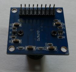
    OV7670 camera module, commissioning, tests with Arduino

    Commissioning as described by the author:
    - download files from github
    -copy "src / lib / LiveOV7670Library" and "src / lib / Adafruit_GFX_Library" to the Arduino folder "libraries"
    -open "src / LiveOV7670 / LiveOV7670.ino" in Arduino IDE and compile and upload to Arduino board

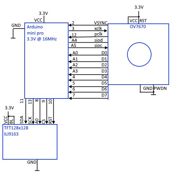
    To avoid the use of logic level converters, I used an Arduino mini pro with a 16MHz resonator, but powered by 3.3V. According to the ATmega328 note, the microcontroller at 3.3V should not be clocked at 16MHz (e.g. it should be the Arduino mini pro 3.3V 8MHz version), but for the purposes of the test such a set simplified the connections and worked properly.

    The author used a 128x160 TFT display, during the tests I connected a 128x128 TFT display with the IL9163 controller.
    Red and blue have been changed in the projected image. For testing purposes, checking if the camera module is working, and focusing - swapped colors are not a problem. If you want to get the right colors by changing the order from RGB to BRG, you can, for example, quickly change the value in the MADCTL register in the Adafruit_ST7735_mod.cpp file:
    Code: C / C++
    Log in, to see the code

    on
    Code: C / C++
    Log in, to see the code


    According to OV7670 camera documentation the module is powered by 3.3V, when connecting to Arduino 5V, take care of the conversion of voltage levels. The module has SIO_C, SIO_D pins, which are an SCCB bus with operation similar to I2C, a serial bus used in the camera configuration. The module responds to the I2C bus at the address 0x21. Inputs RESET (high state, camera operation) and PWDOWN (low state, normal operation). XCLK clock signal input and PCLK output for synchronous data download from the parallel 8-bit D7-D0 bus. HREF and VSYNC outputs synchronizing data download from the parallel bus (the appropriate configuration allows to resign from the HREF signal - line signal, using only VSYNC - frame synchronization).

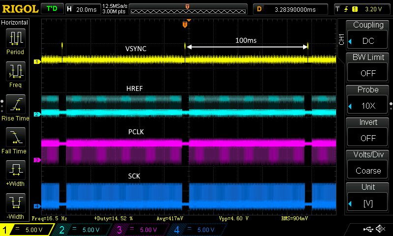
    The basis for starting the module is the appropriate configuration of registers via the SCCB bus. SCCB interface lines should be pulled up to + power supply with resistors 4.7-10kom. It is important that the camera module has a stable 3.3V power supply. For the bus to work properly, give a clock signal to the XCLK input, according to of the application note, the frequency of the input signal should be 10-48MHz (I checked experimentally that with the input frequency at XCLK = 4MHz the SCCB interface responds correctly). The code under test generated the clock frequency XCLK = 8MHz. The frequency of the PCLK signal clocking the data changes on the D7-D0 lines (data should be read on the rising edge) depends on the set dividers and PLL. In the case of the tested code, we get a clock with a frequency of 2MHz on PCLK.
    OV7670 camera module, commissioning, tests with Arduino

    The time interval between VSYNC pulses (interval between frames) is 100ms, i.e. we have ~ 10FPS:
    OV7670 camera module, commissioning, tests with Arduino

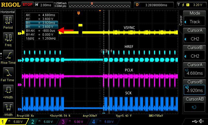
    The interval between HREF pulses (one line) is about 800us:
    OV7670 camera module, commissioning, tests with Arduino

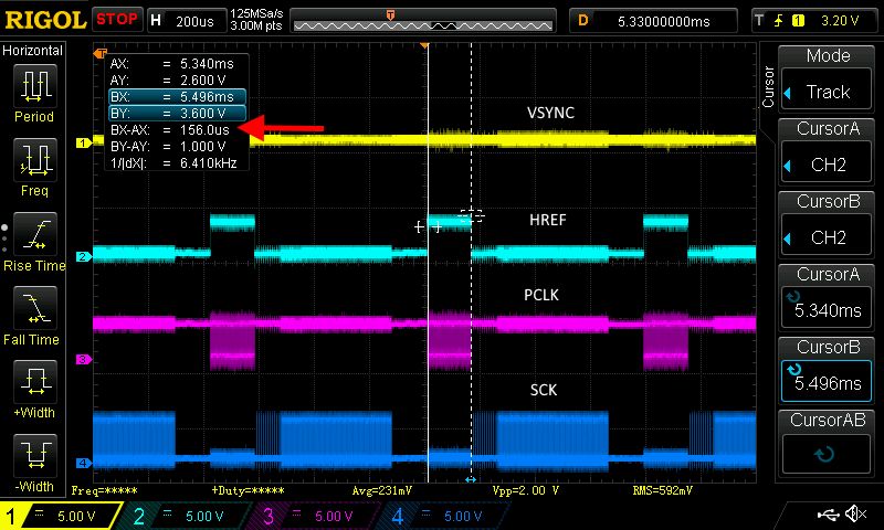
    The transmission time of one line from OV7670 is ~ 156us, the transmission is accompanied by a high state on the HREF line and a clock signal on the PCLK line:
    OV7670 camera module, commissioning, tests with Arduino

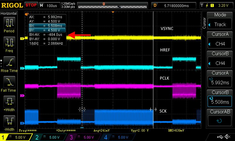
    Between successive transmissions of the OV7670 line, the data is sent to the TFT display via the SPI bus, accompanied by a clock signal on the SCK line, the transmission lasts ~ 484us:
    OV7670 camera module, commissioning, tests with Arduino

    Self displaythe image from the camera on the display is not practical, unless we send digital data over a longer distance via wired or wireless transmission. A more interesting application would be to save data from the camera module to an SD card, obtaining a wildlife camera or a timelaps camera, e.g. for nature observation. The resolution of files recorded by such a camera will be quite hopeless, but the whole thing would be quite cheap and would have an experimental value.

    Saving the image from OV7670 on the SD card

    On page link we will find an idea for a way to save the data from the camera to the SD card. It turns out that the author chose a resolution of 320x240 lower than the maximum 640x480. In addition, he chose the format of reading data from the YUV camera and saves only luminance data to the card, which will result in a black and white image. Finally, to get the BMP file, the files are processed with python script. Not very effective and convenient, why is it difficult to save a color (RGB565) BMP file on an SD card? Well, data writing to the TFT display was sequential and did not require confirmations and additional operations, while the SD card supports the file system. The inefficient Arduino library supporting SD cards and the variable behavior of the SD card make it difficult to quickly and sequentially write data from the camera to a file on the card. Resolution limitation from 640x480 to 320x240 results from the remaining memory for variables after importing the SD card library. One 320px line fits in the remaining memory, while with 640px 16b color is already a problem.

    Summary
    The OV7670 module is cheap and allows a lot of experimentation with image reading and processing. The considerable limitations of the module may discourage less persistent people. You can try to build cheap, simple, small devices for timelaps / wildlife camera experiments. To freely experiment with the processing of camera data, you can choose:
    -a platform that has enough RAM to fit the entire frame with the image (or in the economy version - a single line)
    - camera module with a FIFO memory buffer to which image data will be written, while the reading can be performed at any speed
    - camera module sending image data via serial bus (fewer connecting cables)
    -module with good documentation, libraries / api / examples to configure, so as not to struggle with getting the first frame of the camera image
    -a platform with fast interfaces and computing resources to process data quickly

    Low-level experiments with VGA 640x480 image capture attempts to appreciate cameras and camcorders built into our smartphones, as well as standalone 4K cameras and camcorders :)

    Cool? Ranking DIY
    Do you have a problem with Arduino? Ask question. Visit our forum Arduino.
    About Author
    TechEkspert
    Editor
    Offline 
    TechEkspert wrote 6274 posts with rating 4919, helped 16 times. Been with us since 2014 year.
  • ADVERTISEMENT
  • #2 17394330
    Mscichu
    Level 18  
    I used to test the OV7670 with ATMega8A, which only served to drive a new LCD frame on the SSD1963 driver and to start the webcam. It was flying elegantly with a maximum resolution of 640x480, there were no cuts, but as you wrote yourself, there was no use other than a super cheap electronic door peephole. I was also looking for a serializer to play the picture on the UTP twisted pair, but I stopped this project.

    However, I came back to the matter with webcams only in a different form, which I recommend to everyone. ESP32 + OV2640 (without any buffer) and you can stream to the network as a preview, although at 800x600 resolution it crops just like in your recording when the image changes quickly (jpeg format). I also made a record on an external server in the LAN can act as a photo-trap. Link to the project I used: https://github.com/igrr/esp32-cam-demo

    By the way, omnivision avoids typical technical questions. I asked for the official datasheet or a hint on how to run the STROBE function in OV2640 (the register is available in other modules and here I did not find any data) and they replied that they did not have time to deal with this matter ...
  • #3 17394779
    TechEkspert
    Editor
    @Mscichu if you want and time, feel free to present your achievements in DIY or Articles.

    What PCLK clock did you use with OV7670 + SSD1963 in 640x480 mode?

    In OV2640 I see a disturbingly similar hardware interface as in OV7670, is the configuration of registers also such fun as in OV7670?

    OV2640 has a jpeg "codec" in it?

    I can see there are two versions:
    without additional modules:
    https://botland.com.pl/kamery-do-arduino-i-ra...ry-arducam-ov2640-2mpx-1600x1200px-60fps.html
    https://botland.com.pl/kamery-do-arduino-i-ra...200px-60fps-z-obiektywem-hx-27227-m12x05.html
    and with an additional layout on the board:
    https://botland.com.pl/kamery-do-arduino-i-ra...1200px-60fps-spi-modul-kamery-do-arduino.html
    which communicates serially.
    There is also a version with ESP8266:
    https://botland.com.pl/kamery-do-arduino-i-ra...a-arducam-ov2640-2mpx-modul-wifi-esp8266.html
  • #4 17395962
    Mscichu
    Level 18  
    As for the OV7670 project, it's an old project and I have only scraps. From the diagram of one of the first versions, I can see that on the XCLK I had an input from an external generator and I ordered different ones from 8 through 16, 20 and 24MHz (I still have ;) ) and from what I remember it was working at 24MHz. I gave the camera output to the SN74HC109D trigger which first started the first SNJ54AC573W gate, and then the next one (RGB565 encoding) and at the second clock tick it started the buffer output and the next pixel was recorded on the LCD screen (16bit bus). In addition, after the full frame, when the VSYNC signal appeared that was read from the uC, I sent the SSD1963 the position of the next pixel at 0.0 and so on.
    It was in early 2014. and I have a lot of mess, especially with test projects, so it's not much to show. If someone is willing and wants to review this "bag" regarding OV7670, I can throw in, but I will have to remove the libraries from Kardaś.
    On the other hand, when it comes to the project on OV2640 and ESP32, it is a commissioned project and I cannot disclose the documentation, although I can help.

    As for the registers on OV2640, I did not even go to them. The design I was modeling on was already set up and I didn't bite into the registers themselves. All I did was rotate the image and here is a surprise because after rotating the image 180 degrees it starts to catch a green hue. Not on one because I have already tested 10 pcs. and not only with me because they also have problems on the Internet. OV2640 has a built-in JPEG codec, so I used this webcam, but you can download uncoded image in standard formats.

    As for the choice of OV2640, it was important for me to reduce the costs of future production as much as possible, so I ordered only webcams from China without plates (something like the first link in which you also have the sensor and camera logic power supply). ArduCam would be the simplest solution, but there is a difference of 20 PLN for a camera and 140 PLN ;)
    This version with ESP8266 and this version for PLN 140 have a built-in processor that first catches the frame, and then runs in series and will be suitable for photos, but not for movies. On ESP32 without any intermediate processors I catch one 800x600 frame in 200-300ms. If someone wants to catch 1600x800, you need to increase the encoding and the image looks quite tragic, but it is possible. You would need to add RAM to ESP32 ;)
  • ADVERTISEMENT
  • #5 17396158
    TechEkspert
    Editor
    Interesting experiments.
    So for ESP32 streaming, "raw" frames are read from OV2640, and then compressed and sent over TCP?

    When OV2640 sends a compressed frame, does it send some end of data stamp? (maybe the compressed size may be different and content dependent?).

    Can the jpg data from OV2640 be used for streaming, e.g. in mjpg?
  • #6 17396264
    Mscichu
    Level 18  
    You can pick up as RAW or already compressed, but you can quickly choose the compression quality yourself. The camera always changes the signal to VSYNC after the finished frame, whether it is RAW or JPEG, and the compression itself is handled by the processor built into the camera module. Of course, JPEG files, despite the same resolution, can have different sizes (from 30 to 60kb for me).
    OV7670 camera module, commissioning, tests with Arduino

    On the ESP32 you can also use the built-in memory as a hard disk to save the photo and read it at another time. In the standard ESP-WROOM32 we have 4MB of flash, of which at least half can be used for the file system (it's about 50 photos).
    As for MJPEG playback, it is even a function that sends and refreshes the page over and over again. I tried to save and save as a movie - infinitely long ;) In general, the subject is interesting, although it would be difficult to bite into everything to start from scratch.
  • #7 17396526
    TechEkspert
    Editor
    Smart with this use of VSYNC to inform about the end of compressed jpg data. I understand that in this case HREF does not carry any information?

    What is able to play this "movie" as a saved refresh page?

    The example of these cameras shows that seemingly negligible resolutions, but to easily handle it, very complex platforms using FPGA are created:
    https://botland.com.pl/arducam-kamery-do-ardu...-v2-dla-arduino-modul-kamery-ov2640-2mpx.html

    I found one more compression support module:
    https://botland.com.pl/kamery-do-arduino-i-ra...x-640x480px-30fps-z-obiektywem-hq-m12x05.html
  • #8 17396558
    Mscichu
    Level 18  
    I played what I had on the computer, it was probably VLC or the beak. I will try to record something tomorrow and check exactly what and how. As for the information about the end of JPEG, I can see in the code that there is a comparison of the received buffer to SIZE_MAX but I haven't found SIZE_MAX anywhere in the code, even when I use grep. HREF in jpeg seems to be unused.

    I also saw this webcam, but I had to miniaturize everything so I chose OV webcams :)
  • ADVERTISEMENT
  • #9 17403421
    Mscichu
    Level 18  
    It took me a while to get everything together (especially to find a working ESP program).

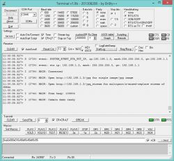
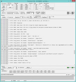
    After programming ESP32 in the command line, we get a message about the correct activation of the camera and connection to the network, which confirms the IP assignment and the ESP32 viewing links:
    OV7670 camera module, commissioning, tests with Arduino

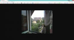
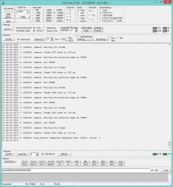
    After copying the address and pasting into the browser, we get a photo and information about the connection and the frame reading time:
    OV7670 camera module, commissioning, tests with Arduino OV7670 camera module, commissioning, tests with Arduino

    When we copy the link with the stream, we get a fairly good image (unfortunately recorded with an external program because I do not remember exactly how I saved / played it). Film taken against the light because I have nowhere to point the camera. General mess and designs that I can't show. I just want to show what the movement in the camera looks like:
    [movie: 628932103b] https://filmy.elektroda.pl/35_1535189875.mp4 [/ movie: 628932103b]
    And frame rate in streaming:
    OV7670 camera module, commissioning, tests with Arduino

    Now a few interesting facts that come to my mind and which I was learning about:
    1. You can connect an SD card and quickly save photos to memory when connecting SDIO
    2. Writing to the built-in flash memory takes forever because about 3s.
    3. Sending the saved photo (internal flash) to an external server takes less than 1s
    4. The OV2640 camera has a built-in pin controlling the flash diode, but there are no descriptions on how to control it. You can, however, read the light intensity from the device register under the address 0x2F and control it with the ESP32 pin
    5. The ov2640 camera has 2 registers - When the cell 0xFF is written 1 or 0. Registers are described in DS quite accurately.
  • #10 17403915
    TechEkspert
    Editor
    A very interesting effect with the use of cheap components. When organizing and expanding, the material can be easily placed as a separate article or a DIY project.
  • #11 17406596
    Mscichu
    Level 18  
    ESP32 is generally a very interesting product. Quite recently, I started running as an MP3 decoder. The library itself works as an internet radio player but can be run to play from an external SD card. Project link: https://github.com/MrBuddyCasino/ESP32_MP3_Decoder

    As for writing the article, it would actually be interesting, but I do not have a flair for descriptions. Everyone has always told me that I cannot describe what I want ;) But if someone needs help, I will be happy to help.
  • #12 17406669
    TechEkspert
    Editor
    Writing is a matter of practice, you can learn a lot from the comments, as is the case with this material.

    I tested internet radio on ESP32 , without an external DAC, the effect is average, but at such a low cost, the experiment is interesting. The sound quality without a DAC can probably be described as close to small crackling FM radios.

    ESP32 is an interesting product and with smaller series ESP8266 loses sense?
  • #13 17406802
    Mscichu
    Level 18  
    In my opinion, ESP8266 is suitable for simple things in serial productions because it is still cheaper than ESP32, so there is no point in overpaying when controlling e.g. a relay. For a hobbyist, it is better to buy ESP32 because for a few zlotys more we have much more efficiency, possibilities and a larger number of pins. An additional advantage in favor of the use of ESP32 by amateurs is the use of one core only for wifi in arduino so the wifi will not stutter and tear. Here I would just like to add that when writing a program like the mentioned internet radio, you can enable or disable access to two cores (MP3 decoding uses both cores, otherwise it won't work), so we have a really strong module for little money.
  • #14 18693566
    brewka87
    Level 13  
    Hello. I'll refresh the topic. A few years ago I used a 640x480 resolution camera to directly drive a display with the same resolution. Like my colleague Mscichu, I built a chip that converted 8-bit data to 16-bit data for the display. I used Attiny2313 to set the camera registers. The whole thing was very low latency because the image was basically displayed on the fly without any buffering of individual image frames. The delay was one pixel. The camera sent the image in the RGB565 standard, two bytes per pixel, which were buffered in two snaps, with the next pixel the content of the snaps was copied to the display. However, I did a little overclocking of the camera and instead of 24MHz I played it on 48 or 52MHz and it was still getting better. I was supposed to use it to build a digital microscope, after changing the camera optics to something more solid. I have not seen such a speed camera -> display even in new phones, and it's been about 6 years since then. I remember the slowest of all this was the display itself. I added a RGB TTL to LVDS converter to this system and connected a larger display, which, despite the additional conversion, displayed with even less smudging. I built a system that did not use any processor for image processing, because I wanted to check if it was possible ;) The effects exceeded my expectations. A few days ago I wanted to go back to this "project" to build an electronic door viewfinder but I would like to be able to capture a single picture frame. ESP32 should be perfect for this, and the preview would be "live" without ESP32. If anyone is interested, please feel free to exchange experiences.
  • #15 18693767
    Mscichu
    Level 18  
    Projects for the OV2640 camera are ready on ESP32. Streaming via ESP to some LCD will be fine, but from what I saw it lags. It's better to connect ESP to wifi and have a preview on the phone. You can find everything under the password ESP32 OV2640
  • #16 18693796
    brewka87
    Level 13  
    Mscichu wrote:
    Projects for the OV2640 camera are ready on ESP32. Streaming via ESP to some LCD will be fine, but from what I saw it lags. It's better to connect ESP to wifi and have a preview on the phone. You can find everything under the password ESP32 OV2640

    Yes, that's right. I was interested in these modules. The point is that, as you have noticed, it is very lazy, and with what I achieved a few years ago (a similar solution to yours) it is a tragedy. By controlling the display directly (almost) from the camera, I got a perfectly smooth image with a practically imperceptible delay, which cannot be said about the ESP32-CAM modules. The only thing I missed was the ability to capture a single image frame to take a photo. I thought to connect ESP32 in parallel to my system. These cheap modules are probably based on JPEG compression, and I need to make it so that the camera sends RGB565, then the preview would go through my system, and ESP would only be for saving photos. Besides, I like to combine :) We probably made similar layouts, the idea was the same, only a slightly different layout solution. I would like to come back to that, because I have probably 20 or more cameras.

    Update:
    I am ready to give someone willing to help with the topic: POA030 camera + Kyocera connector + UMSH-8377 display + tape + zif 40 connector.
  • #17 18705281
    Mscichu
    Level 18  
    At the moment I will not help with the work, but I can give you some hints. The OV2640 camera can be controlled like the OV7670, i.e. with an RGB565 output. The processor, e.g. ESP, can only listen on the line and, if necessary, switch the camera to JPEG recording, make a quick record and change back to RGB565 transmission. You can then take e.g. photos of higher resolution.


    I, on the other hand, have a different dilemma. I would like to send such a video signal over a greater distance and thought about using Serdes chips, but I have never dealt with such devices. Maybe he knows whether with a system such as PTN3700 with LVDS output I can send the signal via UTP CAT5 cable for a distance of 20-30m? According to calculations, about 150mbit / s is needed for RGB565, 640x480 resolution and 30fps.
  • #18 18705521
    brewka87
    Level 13  
    Thanks for the hint, but I would like to use a camera with Pixelplus POA030R for this project, because I have several dozen of them. I also have an older version of the PPV401C with the PO6030K system in the amount of a dozen or so pieces. There is a lot to experiment on and disassemble the camera to add better optics, I don't feel sorry - during the experiments I damaged a few copies, because the ribbons are delicate and there is always a temptation to improve something. I also have several dozen UMSH8377 displays, so I want to use it.
    I do not know the layout you are writing about, but I also wanted to send the image from this camera over longer distances and, just like you, I was looking for the SERDES system and probably Texas had something on offer that could work, but I do not know if at such distances. The LVDS DS90C383 transmitter worked nicely on a dozen or so centimeters, but from what I remember it needed 4 data pairs plus one clock pair, and I also needed a twisted pair, because it was cheap and easily available. Maybe if I use an HDMI cable (differential pairs) it would be more? I still have old boards (prototype spiders) somewhere and I think I'll test it myself. The transmitter needed the input RGB888 signal (8 bits per color), PLCK clock signal and vertical and horizontal sync, but I controlled it with RGB565 signal, leaving the youngest bits disconnected (or pulled to ground, I don't remember exactly). I was able to use the 18-bit version of the DS90C363, but I didn't have it at hand. I also assembled the receiver on the DS90C384 and it was all working on the desk. The undoubted advantage of these systems is the housing more convenient to use compared to BGA (I etched the boards personally). In a few days I will be on the plot, I will bring everything home and the experiments will start again ;)

    And yet it will not work with the DS90C383 / 384 system, because there are only 4 differential pairs in the HDMI cable (I probably even thought about it a few years ago and gave up, and now sclerosis), but the mentioned 18-bit DS90C363 / 364 only needs 3 data pairs + clock, i.e. 8 wires ...
  • #19 19019795
    DJ.TRoX
    Level 18  
    For the last few hours I have had doubtful pleasure with the OV7670 module and I have completely given up. The situation is that I am rushing the module with a 16MHz clock. I set I2CWrite (0x42, 0x11, 0x1F) that is prescaler = 32 and I2CWrite (0x42, 0x3E, 0b10010) that is an additional clock divider = 4. My PixelCLK = 62.5kHz works and it's great. I would like to make it work with the maximum resolution of 640x40. According to the documentation, you can take 15 frames in this resolution when in YUV mode. With my clock, with 2Byte / pixel I should be 1 FPS per 10s. What I would not do Vs comes every 3.2s, i.e. in much lower resolution mode. The only register that says resolution is 0x12 (COM7) and logic dictates that it should be set to 0 for YUV or 0b100 for RGB. Any ideas?
  • #20 19021154
    TechEkspert
    Editor
    Również pokonało mnie konfigurowanie rejestrów w OV7670 i wykorzystałem https://github.com/indrekluuk/LiveOV7670

    COM7 0x12 domyślnie 0x00
    http://embeddedprogrammer.blogspot.com/2012/07/hacking-ov7670-camera-module-sccb-cheat.html
    Bit[7]:
    0: Nothing
    1: Reset all the registers to default values

    Bit[5]:
    0: Nothing
    1: Use CIF format

    Bit[4]:
    0: Nothing
    1: Use QVGA format

    Bit[3]:
    0: Nothing
    1: Use QCIF format

    Bit[1]:
    0: Disable color bar
    1: Enable color bar

    Bit[2, 0]:
    00: YUV
    01: RGB
    10: Bayer raw
    11: Processed bayer raw
  • #21 19021445
    DJ.TRoX
    Level 18  
    Thanks, I have already roughly covered it. The first meeting with the device makes a bad impression, but when you start to understand what you are doing, everything somehow holds together. Interestingly, XCLK can be slowed down to almost zero, even though the documentation says it's a minimum of 10MHz.
  • #22 19029819
    DJ.TRoX
    Level 18  
    However, I do not understand this camera. It is so that I raised the XCLK to 8MHz, which works for all of them - for me too. I want 640x480 images, I set the prescaler to 32 so one frame down to a few nice seconds. Examples of VGA configurations are for YUV and RAW Bayr RGB modes. Both fall off because I do not have so much memory in the processor and I must use RGB555 or RGB565. My configuration looks like this:

    [code:1:1df5ab9a09]
    I2CWrite( 0x42, 0x11, 0x1F); Wait_ms(100); // CLKRC 1F --> presc=32
    I2CWrite( 0x42, 0x12, 0b100); Wait_ms(100); // rgb mode

    I2CWrite( 0x42, 0x0C, 0x00); Wait_ms(100);
    I2CWrite( 0x42, 0x3E, 0x00); Wait_ms(100);
    I2CWrite( 0x42, 0x70, 0x3A); Wait_ms(100);
    I2CWrite( 0x42, 0x71, 0x35); Wait_ms(100);
    I2CWrite( 0x42, 0x72, 0x11); Wait_ms(100);
    I2CWrite( 0x42, 0x73, 0xF0); Wait_ms(100);
    I2CWrite( 0x42, 0xA2, 0x02); Wait_ms(100);

    I2CWrite( 0x42, 0x40, 1
  • #23 19030093
    TechEkspert
    Editor
    It was quite a long time and I remember a problem that I did not fully investigate, maybe you also came across it,
    too low xclk value (prescaler probably had no influence on it) hindered the work of I2C,
    maybe it is worth reading the written registers and checking if the records are done correctly?

    The order of the register configuration also seemed to matter, but as I write it was a long time ago and I can be wrong.
  • ADVERTISEMENT
  • #24 19031268
    DJ.TRoX
    Level 18  
    Thanks for your interest in the topic. With the clock I went down to 40kHz, as part of the test, the waveforms looked normal but their content was not. 8MHz is only 20% below the catalog minimum. I ordered several of these cameras and they all behave identically. I'm afraid I've run a mode that nobody has tested. Of course, with time I will come to a conclusion, I am more worried that this time will be qualified for learning and improving my own, and not for the implementation of the project. Life...
  • #25 19041284
    Mscichu
    Level 18  
    Maybe you came across as I did in the past, not on OV7670, but on 7671?
  • #26 19045463
    DJ.TRoX
    Level 18  
    The module says 7670. I have two pieces and if they behave a bit differently from each other, they both return a color similar to black and white cemetery photographs. The average of the colors as 8bit b & w looks bearable and I have to stop there because the YUV mode is only encoded on 4 bytes and I just have no space for it in the frame and I have no computing power for converting from RGB. I wonder if the color would be correct in YUV mode and I will definitely check it when I catch some time.

Topic summary

The discussion revolves around the OV7670 camera module, its configuration, and integration with Arduino platforms, particularly focusing on image processing at VGA resolution (640x480). Users share their experiences with the OV7670, detailing challenges in register configuration and clock settings, as well as comparisons with newer models like the OV2640. Various projects utilizing the OV7670 and OV2640 are mentioned, including streaming capabilities with ESP32 and the use of different output formats (RGB565, YUV). Participants also discuss the limitations of the OV7670 in terms of processing power and memory, and the potential for using Serdes chips for long-distance video signal transmission. The conversation highlights the importance of understanding register settings and clock configurations for successful implementation.
Summary generated by the language model.
ADVERTISEMENT