PIC18F45K50 as WS2812 LED strip driver (theory+library)
TL;DR
- PIC18F45K50 drives WS2812 RGB LED strips with a custom C library and a theory section on the LED’s single digital control signal.
- The library sends GRB data as 24 bits per LED, chains DIN/DOUT across LEDs, and uses pulse timing plus a low reset of at least 50 µs.
- Implementation uses MikroC PRO for PIC, inline __asm nop waits, and a 20MHz quartz on an older PIC18F45K50 board; PIC18F4550 would also fit.
- Effects from Adafruit_NeoPixel and Tweaking4All run by swapping only the WS2812 control calls to this library.
- The current version supports one LED strip at a time, and timing must be retuned if the microcontroller clock changes.
Generated by the language model.
 .
.
Hello my dears .
Today's topic will be the WS2812 LED driver. First I will describe its operation from the theoretical side, and then I will present my library to support it designed for the PIC18F45K50.
What is WS2812? .
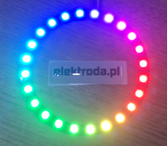
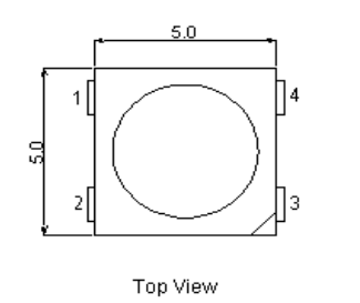
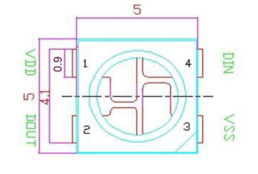
The WS2812 is an intelligent LED controller connected to an RGB LED. It allows you to control a large number of LEDs with essentially one pin, but more on that later. We'll start with what you see at first glance, the housing. The whole thing is housed in a single SMD 5050 housing - meaning it measures 5mm by 5mm!
 .
.
 .
.
 .
.
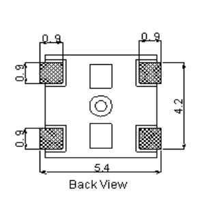
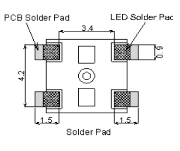
As we can see, the whole thing resembles a simple LED. Here the question arises, where is all the intelligence of the driver? Just look at the pins to understand this:
 .
.
The WS2812 LED has only four pins, consecutively:
| No. | Symbol | Description | |
| 1 | VDD | Power supply | |
| DVDD | 2 | DOUT | Out control signal |
| 3 | 3VSS | Weight | |
| 4 | DIN | Control signal input |
We will probably be most interested in the pins associated with the control signal. There are only two - input and output. What does this mean?
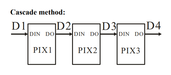
It means that the WS2812 is controlled digitally and, what's more, the signal given to one diode can be sent to the next diode by connecting their DIN and DOUT pins - this allows multiple diodes connected in this way to be controlled by a single pin !
This combination of WS2812 diodes looks as follows:
 .
.
Of course, you also need to lead GND and VDD to each, this is not shown in the diagram above. A really large number of LEDs can be connected in this way, however you will need a microprocessor with a suitable protocol developed to control this.
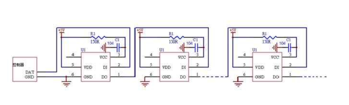
To summarise, in practice, the whole thing looks like this:
 .
.
Control protocol WS2812 .
All control is done via a single digital signal which we feed to the DIN pin of the first LED. The signal sends the colour bits (appropriately coded) sequentially. There are 24 bits per LED (3 bytes - Red byte, Green byte, Blue byte). This means that we can display a wide range of colours, theoretically as many as 2^24 i.e. 16777216 different shades! The specified bits respectively go on until we freeze the output signal in the low state for at least 50us.
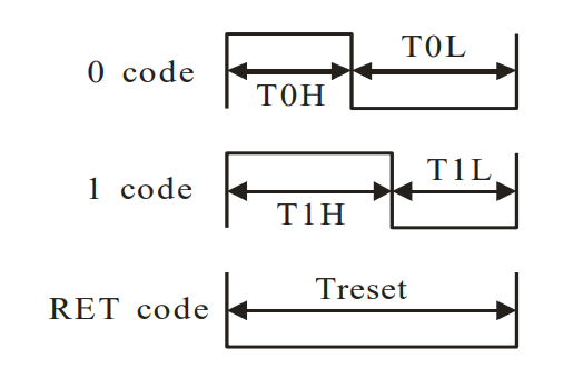
The bits themselves are encoded with the help of applying a high and low state on the pin through the appropriate time.
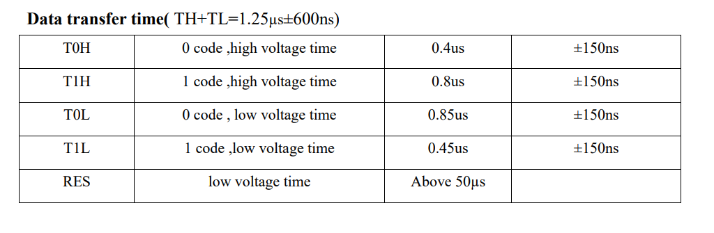
In summary, according to the image (from the WS2812 datasheet note):
 .
.
- if we want to transfer a bit 0, we set the communication pin to high state at time T0H and then to low state at time T0L
- if we want to transmit a bit 1, we set the communication pin high at time T1H and then low at time T1L
- if we want to communicate that we terminate the data transfer (i.e. after this break we can control the LEDs again from the beginning), we set the pin to low state at least for the time Treset
The times are given in the table:
 .
.
The colour coding is as follows:
| G7 | G6 | G6 | G5 | G4 | G3 | G4 | G2 | G1 | G0 | G0 | R7 | R6 | R5 | R4 | R4R3 | R2 | R1 | R0 | B7 | B6 | B5 | B4 | B3 | B2 | B2B1 | B0 |
Yes, this is GRB, not RGB. The 8 bits of green are transmitted first, then red, and finally blue. The transmission starts with the oldest bits.
Between colour transfers for subsequent LEDs there is no interval - simply continue transmission and the WS2812 will take care of everything. .
After sending all the bits (for all the LEDs we want to handle) we wait for the Treset time (low state on the pin) and we can send the bits again.
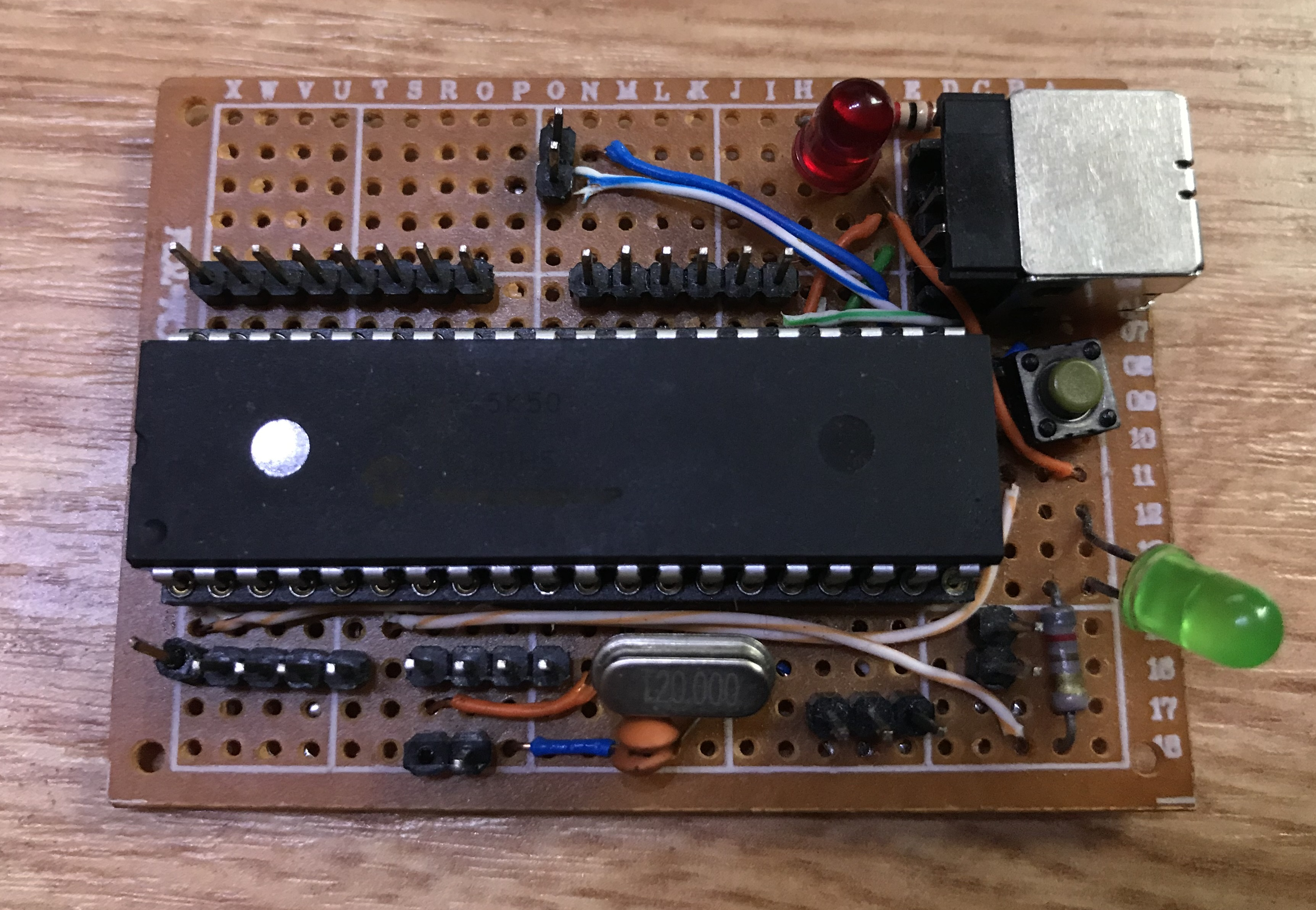
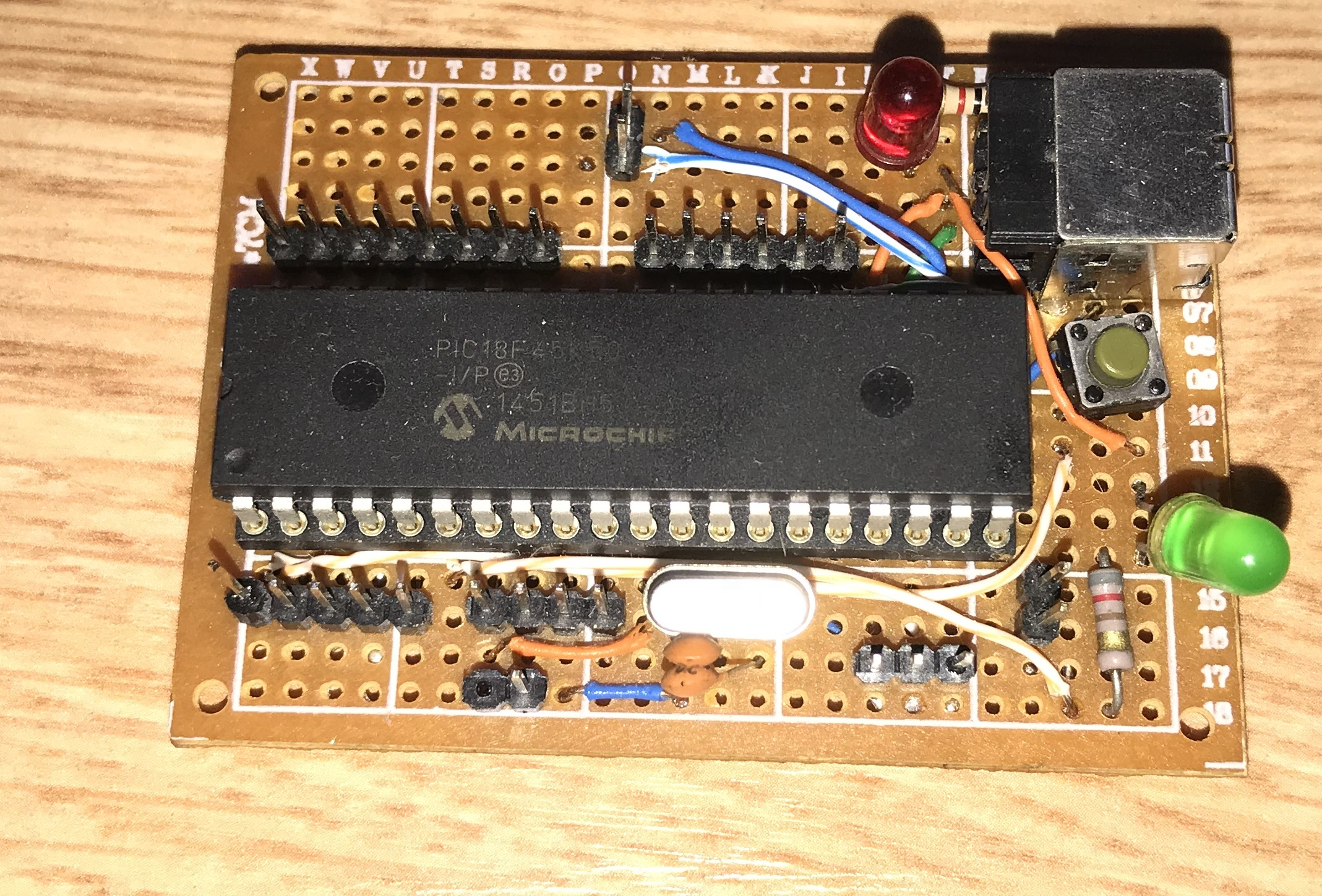
Used board from PIC .
For the project I used one of my older boards with the PIC18F45K50 (the PIC18F4550 would also fit here, as the two microcontrollers are almost identical, although the 45K50 version, for example, has a better precision internal oscillator than the 4550). This board has a 20MHz quartz oscillator. Apart from that, it contains only fairly basic components such as a resistor from RESET, capacitors, a USB connector (here only used for power supply), etc.
 .
.
I know this board looks the way it does, but it was one of my first designs a few years back. The others were already taken. I've been using so many PICs lately that I think I'll soon make some good PIC18F4550 board for myself, but fully in SMD.
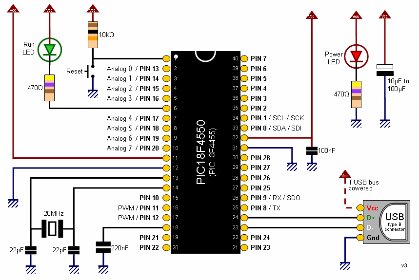
Schematic of my board (this is a Pinguino schematic, but I programmed the board in MicroC):
 .
.
Developed library .
There are a lot of ready-made LED animations for the WS2812 on the web, and it would be silly not to use them - that's why I developed my library in such a way that I could eventually plug ready-made code from the web into it without any problems. I implemented the communication itself in C code with a little help from inserts __asm nop to be able to wait at least a little more precisely the required times T0H, T0L, T1H, T0L. The precision was not perfect, but the whole thing got off the ground nonetheless.
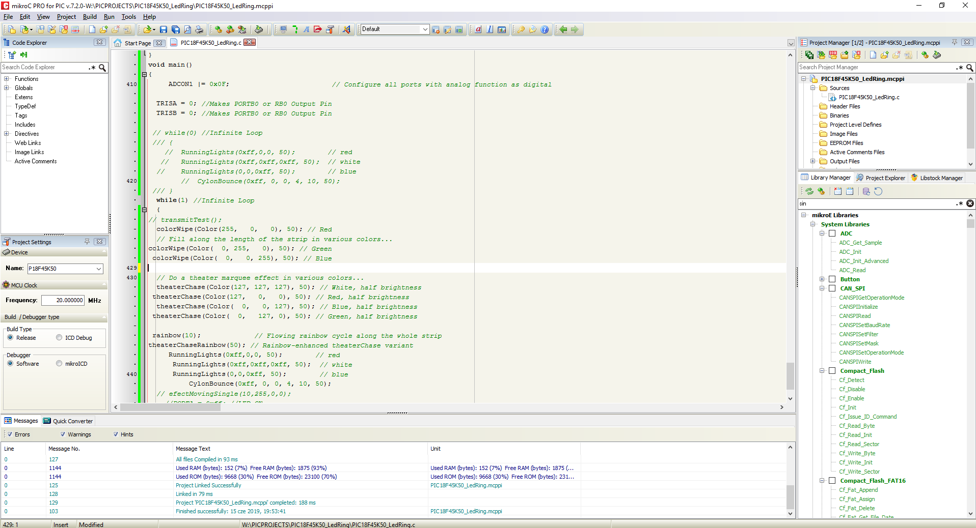
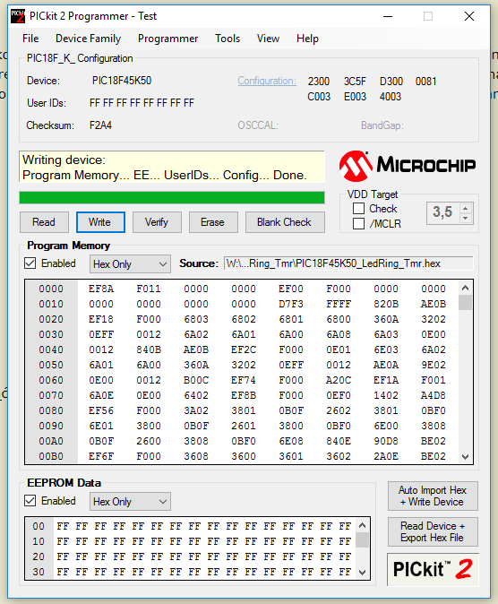
I wrote the library in the MikroC PRO for PIC environment, but it is so simple that porting it to another compiler would not likely be a big problem. I programmed the whole thing using my simple PICKIT2 clone.
Screenshot from MikroC PRO For PIC:
 .
.
Screenshot from PICKIT2 during programming:
 .
.
Screenshot of the whole during library development:
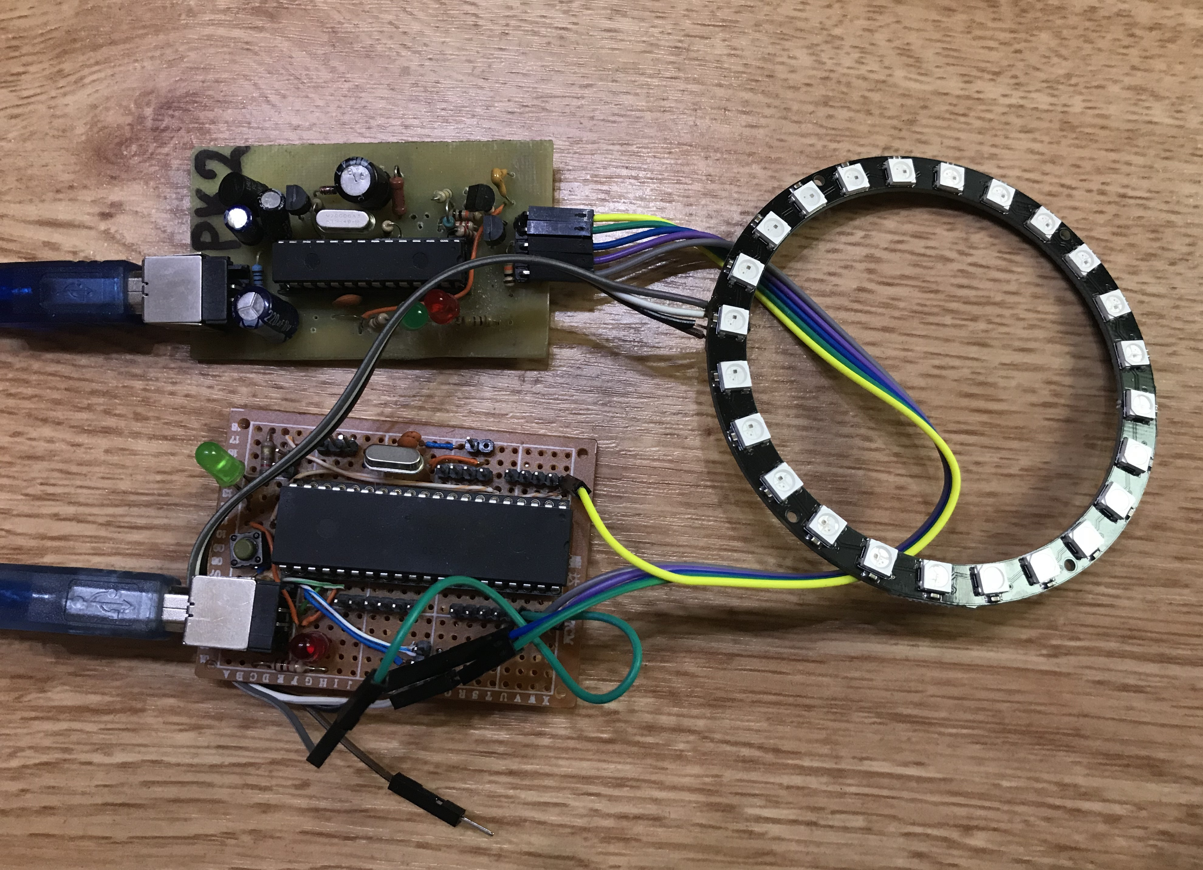
The library itself is very straightforward, while porting it to other microcontrollers will probably only involve changing the handling of the corresponding wait times. It is worth remembering that in the current version it uses nop to wait, so when changing the microprocessor clocking these waits should also be corrected.
The configuration of my library basically just involves setting three variables from the WS2812.h file:
Code: C / C++
The first two variables specify which port the LED bar is on, and the third the number of LEDs in the bar.
The library at the moment is not made to support several separate LED strips at once, but in general this is easily possible. I will probably add support for this in the future (when I buy more strips) and will update this topic then.
The library could be optimised in a couple of places, e.g. by unwinding the for loop, etc.
. Effects .
As intended, I developed my library in such a way that I could then painlessly plug ready-made lighting effects from various libraries into it. In particular, I have taken to:
https://github.com/adafruit/Adafruit_NeoPixel
and
https://www.tweaking4all.com/hardware/arduino/adruino-led-strip-effects/
The videos show the PIC18F45K50 with my library playing various effects:
And here the main function code main() used in the above videos:
Code: C / C++
The code itself for the individual animations is copied from the sources above, only the WS2812 control function calls are swapped to mine.
Summary .
I liked the WS2812 LED driver very much. It is easy to use and cheap. You can get a lot of variety of LED strips on the web and not only based on the WS2812.
I think that even the information in this topic alone would allow anyone to write the WS2812 support code themselves, but I'll still be tempted to post my library here:
.
And an example of its use (the effects themselves are from Adafruit, ported to C):
.
I am also attaching the WS2812 datasheet (source of images from the WS2812 communication description):
.
And screenshots of WS2812 libraries from the web which I used as a template and animation source:
.
.
.

p.kaczmarek2 wrote 14628 posts with
rating 12647 , helped 655 times.
Been with us since 2014 year.
Comments
I have recently been controlling these LEDs via ARTNET. I made myself a controller from an ESP-32 module. Unfortunately the ARTNET library on the ESP has a bug, sometimes the whole thing crashes if there... [Read more]
I have just had a 1 metre 60led/m tape ordered from ALI for just under PLN15. https://obrazki.elektroda.pl/3025688800_1560773732_thumb.jpg . I do not show the name of the seller from whom I bought,... [Read more]
The problem with software control is, for example, the handling of the encoder or other interrupts. Then the effects are already harder to do without "flashes and clipping". But overall, the price/quality... [Read more]
The only thing I don't quite like is the minimum brightness of the LEDs (at 0x01 per channel), it could have been slightly lower. Overall though, there is no point in using regular RGB LEDs anymore, it's... [Read more]
And what fabulous things can be created with the WS2812b :) . . . . . [Read more]