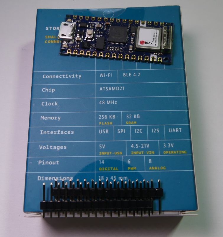
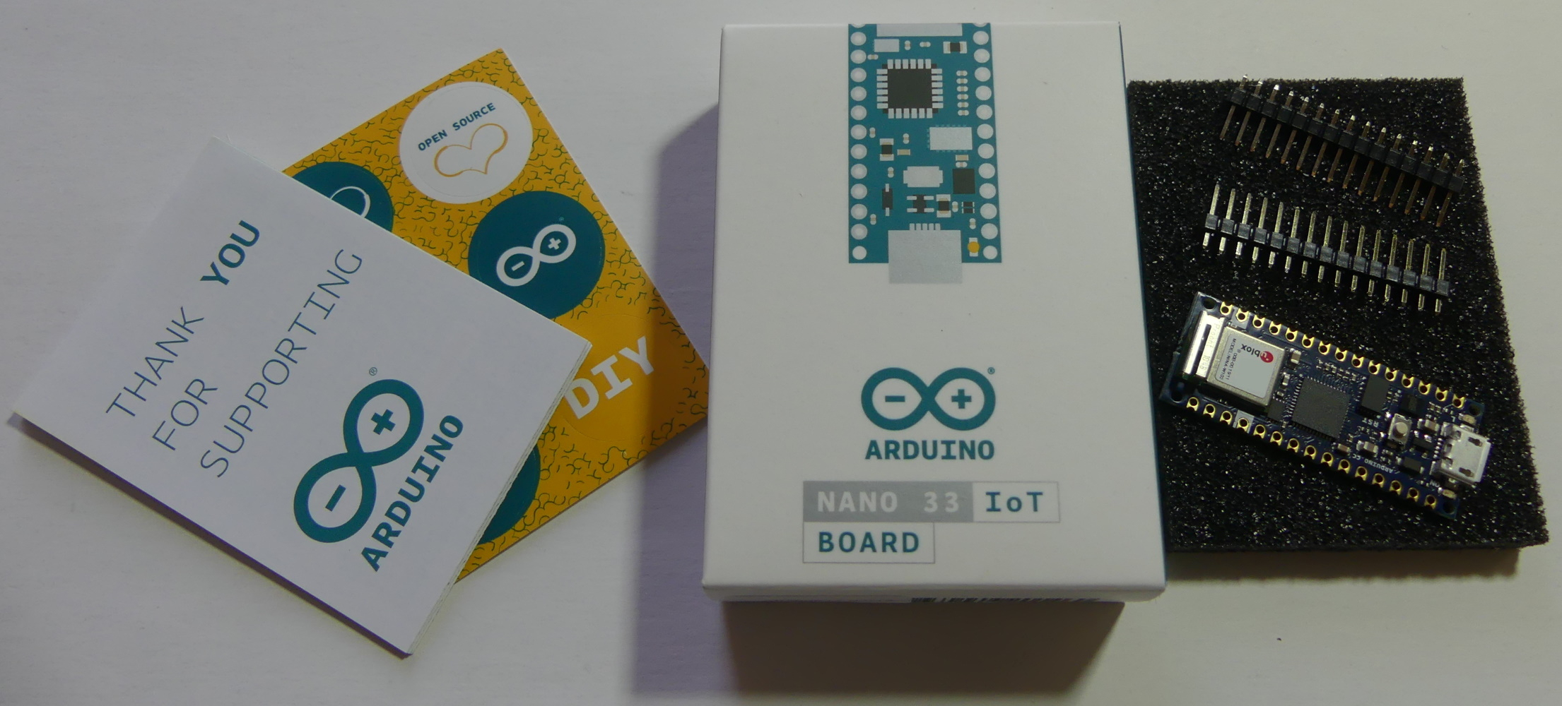
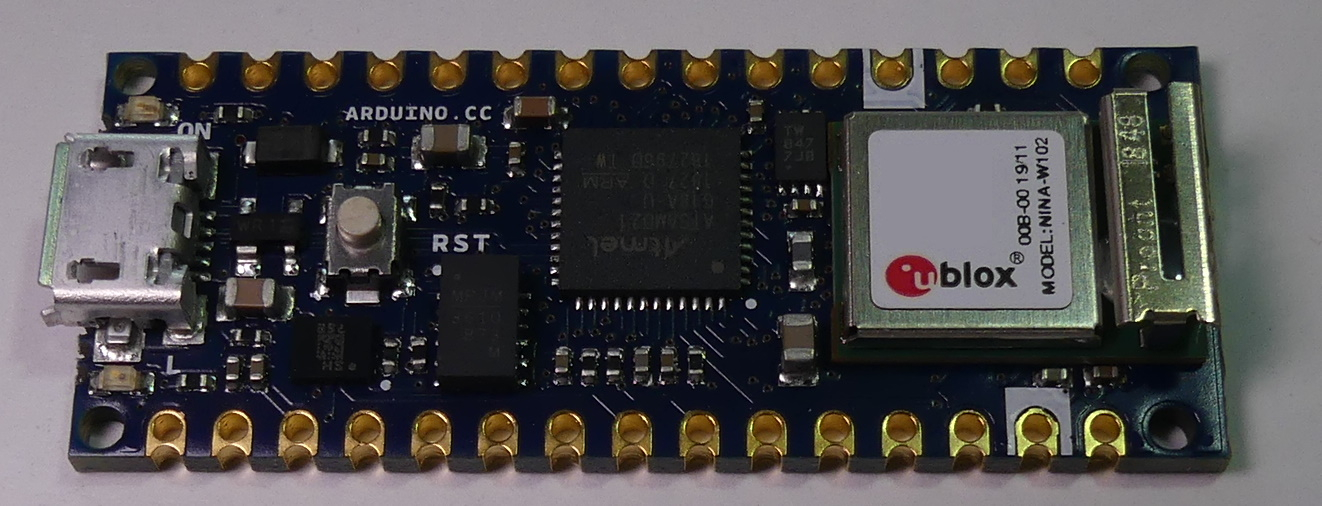
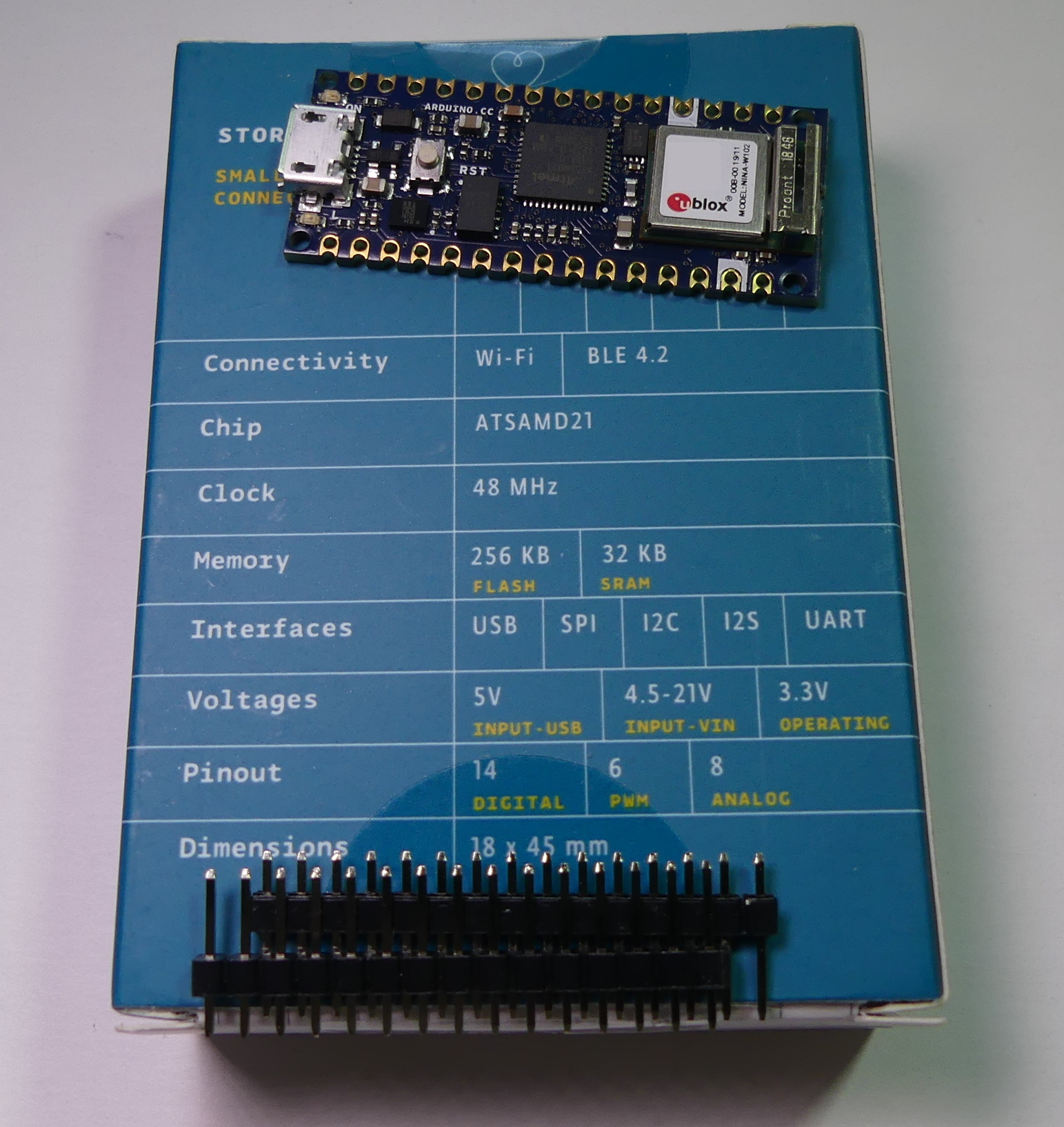
Arduino NANO 33 IoT is a new version of the NANO module with 3.3V logic levels (note the extension modules with 5V I/O), ARM microcontroller
SAMD21G18A , WiFi and Bluetooth connectivity
NINA W102 , and 6-axis IMU
LSM6DS3 . The PCB has a secure key storage
ATECC608A used in secure communication with the Arduino IoT cloud. The board allows SMT (surface mounting), or soldering with using goldpin pins. The microcontroller is clocked up to 48MHz, is equipped with a 256KB flash memory and 32KB RAM. In addition to PWM outputs, a 10b DAC output is also available. ADC have a resolution of 12b. The version
1.8.9 Arduino environment was used to tests the module .


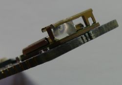
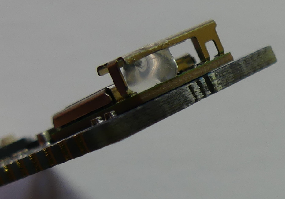
The WiFi / BT module antenna is made in the form of a metal fitting, protected anti vibration by a drop of thermal glue:
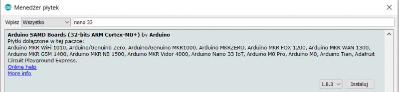
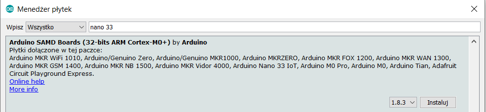
We add a "nano 33" board Tools -> Board -> board manager:
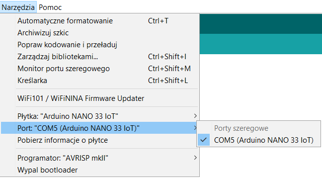
We choose the board and port:

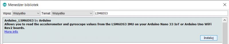
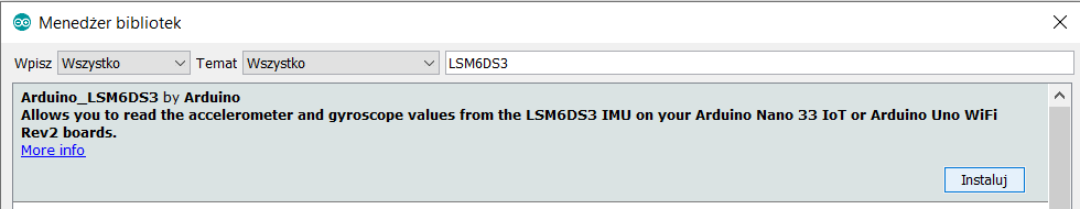
If we want to use IMU, you can add LSM6DS3 library:
An accelerometer or gyroscope may be useful for controlling vehicles, e.g. a two-wheeled balancing vehicle, or stabilizing / positioning the camera, or it will enable detection of movement and waking up the device, maybe in fitness applications. Maybe it is possible to count the number of steps or type of activity?
Let's test the functionality of the Arduino IoT cloud.
We set up an new account:
https://www.arduino.cc/en/IoT/HomePage
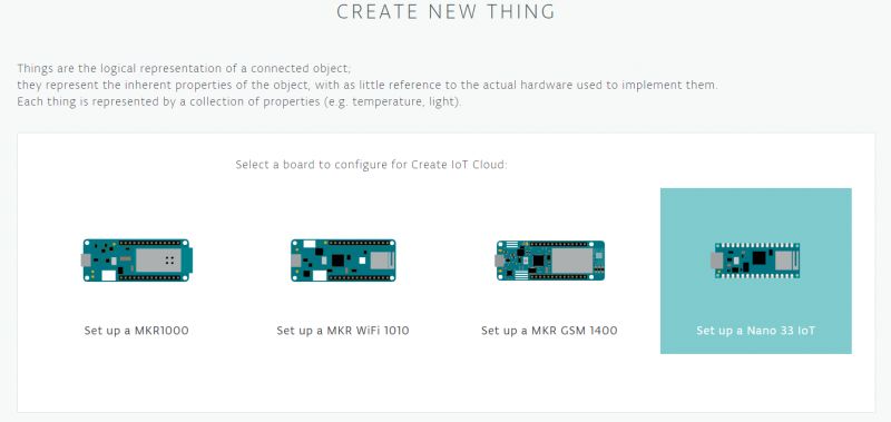
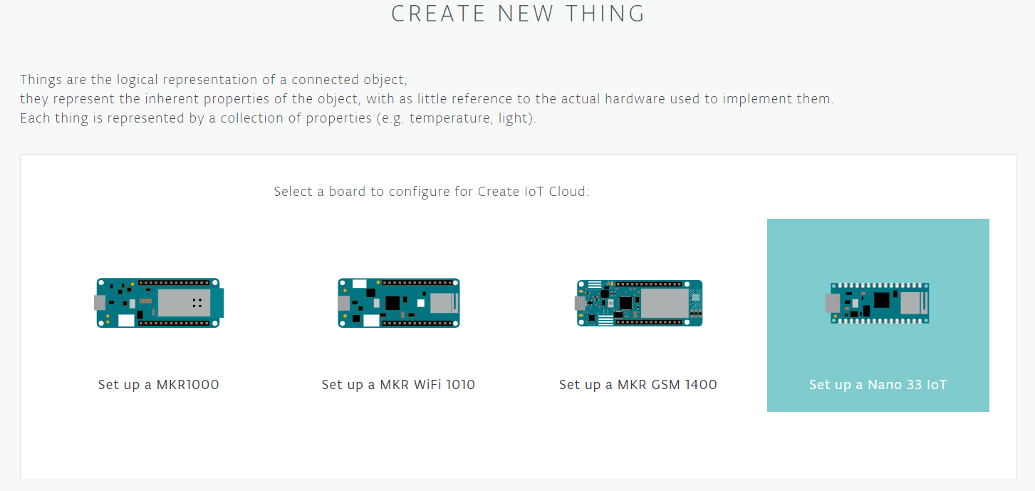
after creating the account, click "NEW THING" on:
https://create.arduino.cc/iot/
We choose the Nano 33 IoT board model:
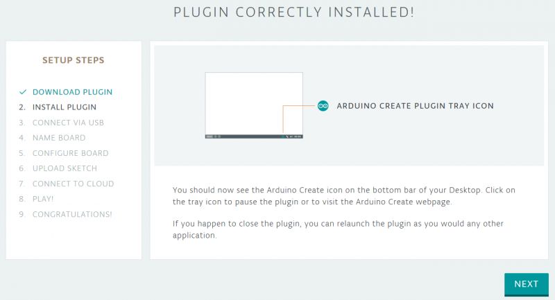
To configure the board from Chrome or Firefox browser, we can download and install the 'Arduino Create' plugin. After successful installation, the plugin will be detected in the browser, and an icon will appear in the system tray.
The debug console is available at
http://127.0.0.1:8991/
I used Firefox for testing.
We connect the board via USB, when it is detected we give it a name.
We go to the board configuration, the first stage is the automatic configuration of the cryptographic system.
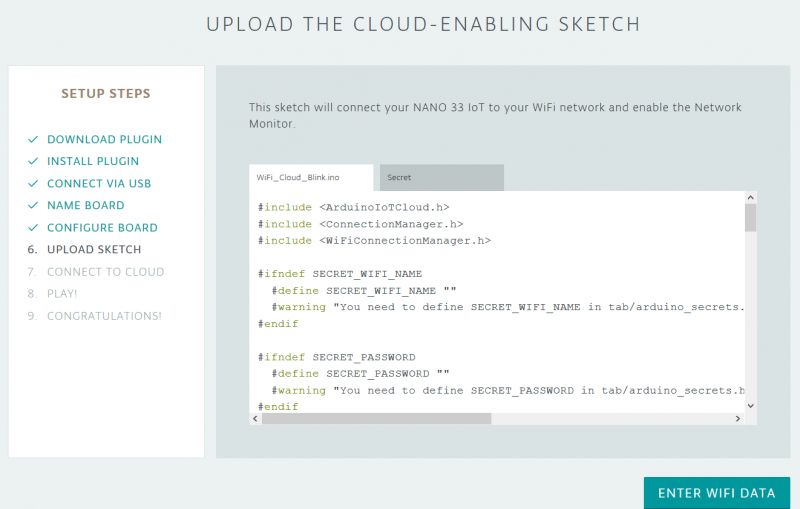
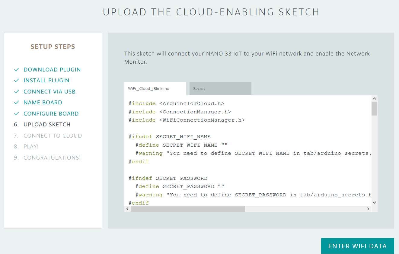
We get the start code to upload to the board, and the ability to enter the password and the name of the 2.4GHz WiFi access point:
The added device can be found here:
https://create.arduino.cc/devices/
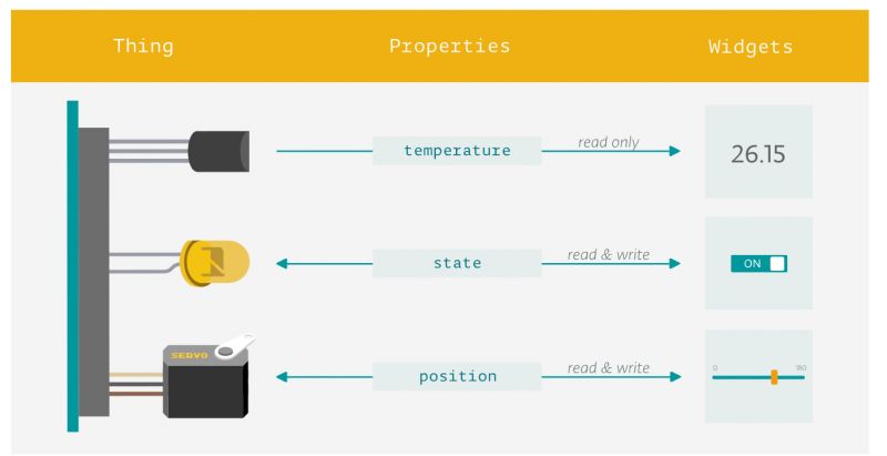
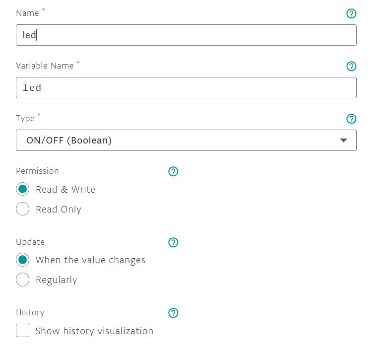
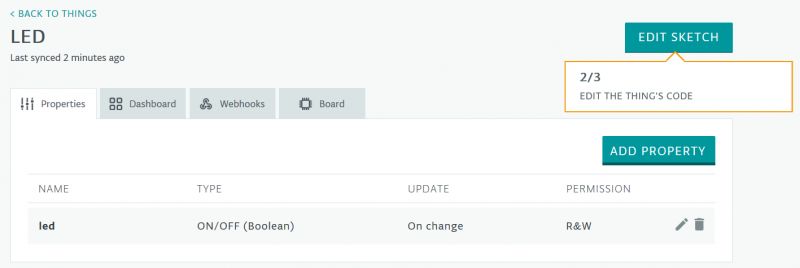
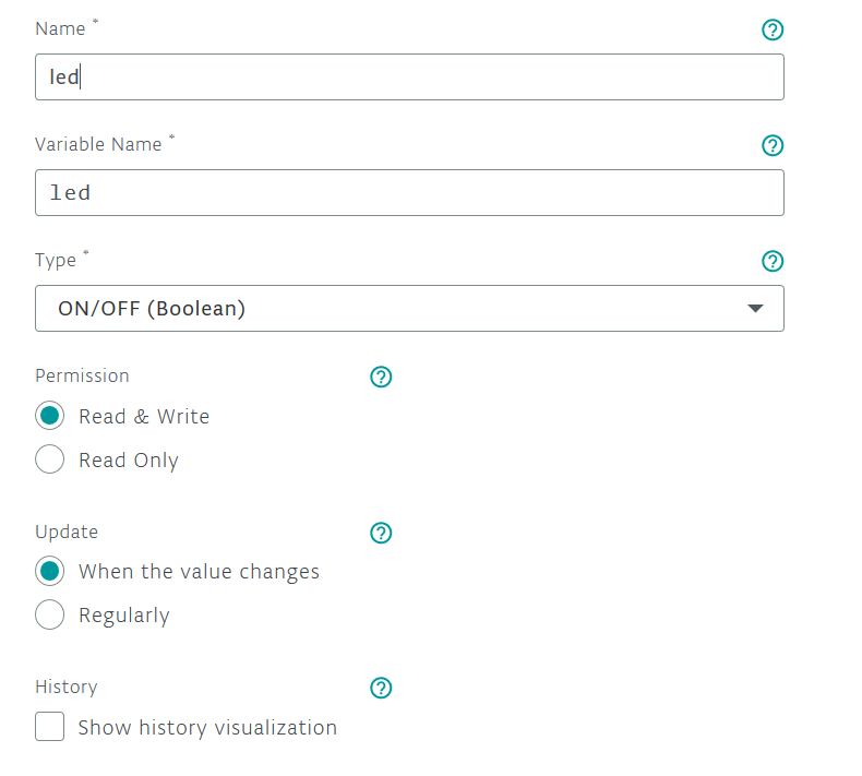
We add the ability to control the LED on the board:
https://create.arduino.cc/iot/things
and we go to the online code editing:
https://create.arduino.cc/editor
in function:
void onLedChange () {
// Do something
digitalWrite (13, led);
}
we add line:
digitalWrite (13, led);
which will allow you to control the LED on the board using the Arduino cloud.
In the setup section we also add output configuration 13: pinMode (13, OUTPUT);
We compile code and send it to the board, now we can return to IoT cloud.
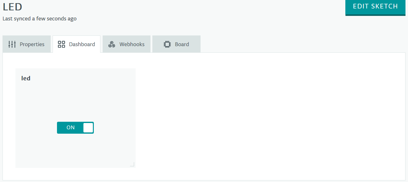
We can control the variable led, and then togle LED using the browser:

The web interface of the editor and IoT cloud works quite slowly, and sometimes errors appear, but we can easily test the properties of IoT devices.
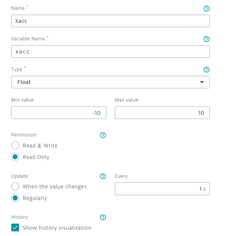
Let's try to read the values from the accelerometer on the PCB and send them to the cloud.
We add the ability to read one of three acceleration values sent by the accelerometer:
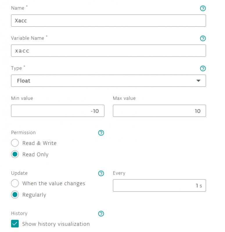
We can modify code in the online editor:
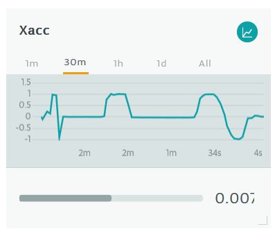
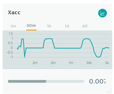
We can observe in the browser value changes sent by the IMU:
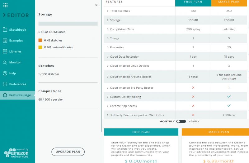
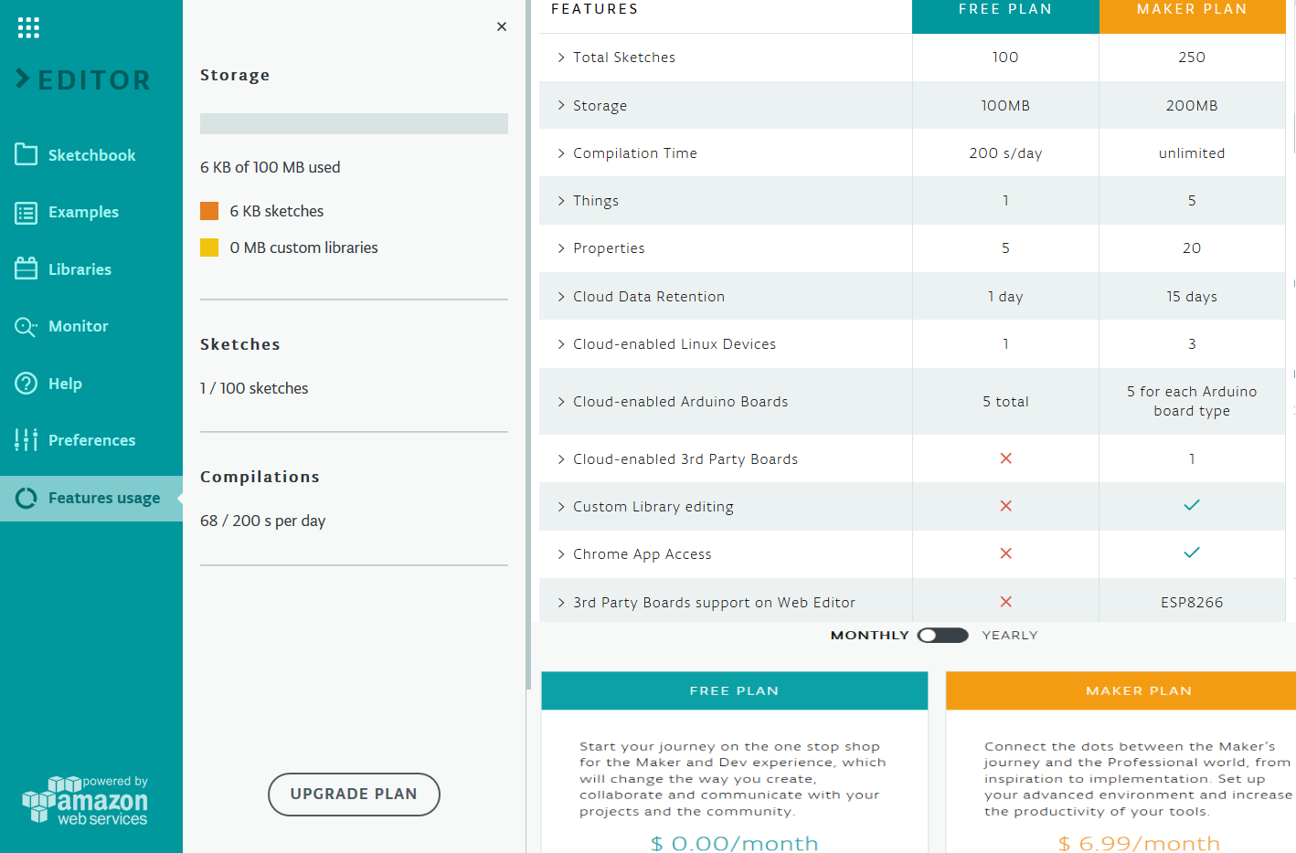
Free and paid access to the online editor and cloud has its limitations:
 Let's take a break from the cloud and go back to the offline editor without restrictions, try using 12b ADC converters and 10b DAC converters.
As an example, we will launch an electronic load with regulated power. Usually in such systems we have regulated constant current forced by artificial load, this time we will try to force constant power.
The voltage at the DAC0 output (pin 4) after a 3-4x gain will drive the gate of the MOSFET (select the gain to use the entire DAC range and provide the appropriate voltage at the transistor's gate).
At the ADC A1 input (pin 5) we give the input voltage from the loaded system given by a 1:10 divider, the input voltage 0-20V will correspond to 0-2V.
At the ADC A2 input (pin 6) we give the amplified voltage on the 0.1om resistor, which is used to measure the current flowing in the system. A 10X gain will provide 0-2V for 0-2A.
On the ADC A3 input (pin 7) we give the voltage set by the potentiometer, these will be the power settings that will load the connected power source.
On the serial console we will observe the set power, voltage and current as well as the drawing power.
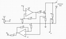
The output voltage and current will allow you to calculate the power P = U * I, while controlling the gate voltage of the MOSFET will allow you to adjust the current.
By changing the control algorithm, an dumy load with a constant resistance or a constant current can be obtained, however, a DC electronic load with constant current can be built based on a single operational amplifier.
A controller can be used for control
PID however, for the sake of simplicity, we will only use block I. The response time will be quite long, but the system will strive for constant error minimization.
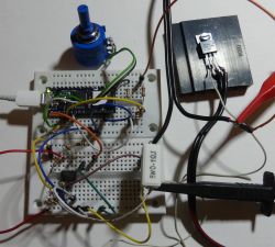
This is how a primitive test system looks:
Test Code:
In a serial console you can observe the operation of the system:
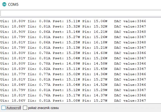
The results are average, there is a noticeable error in voltage measurement, the system has quite a long response time (it resembles a little manual turning of the instrument knob), but tries to maintain constant power regardless of changes in voltage of the connected power supply. It can be a prelude to experiments of this type, both with the code and with the system part (both worth expanding).
Arduino NANO 33 IoT is twice as expensive as the previously tested
Arduino NANO Every and is equipped with a microcontroller with more resources and richer periphery. Higher resolution ADC and presence of DAC can be useful in projects with analog signals. The board works with 3.3V voltage. The module has an IMU chip and WiFi and BT connectivity, cryptographic chip, and support for IoT Arduino IoT cloud. I was surprised by the limitations of the online compiler from Arduino, and IoT cloud limitations in both the free and paid version.
What ideas do you have for using Arduino NANO 33 IoT, what do you think about online tools and cloud IoT from Arduino?


Comments
I will only add that Arduino NANO 33 IoT is supported by PlatformIO ( link ), also in the field of debugging (Atmel-ICE, Black Magic Probe or J-LINK) programs written using Arduino HAL. Added... [Read more]
Thanks for the hint, I don't know how it works? e.g. J-LINK need to be connected to some specific pins, is it a microcontroller property made available e.g. via USB on a board. [Read more]
Here you will find the answer: https://medium.com/@manuel.bl/arduino-in-circuit-debugging-with-platformio-9f699da57ddc [Read more]
OK, I understand, you can solder, but a more convenient connector would be "pogo pins". [Read more]
Probably yes, but this board is primarily intended for installation in a contact plate (after soldering the pins) - how many "arduinians" does the debugger use? ;) [Read more]
This system costs over PLN 100, which is almost as much as Raspberry Pi 3! It's a pandas twice as much as ESP-WROOM-32, and I don't see a great advantage of this system over ESP32. [Read more]
It is actually a "collector's" price. On the other hand, people still buy honest, original Uno for PLN 90+, so why not wonder. I do not see any advantage over ESP32 at all, because NINA W102... [Read more]
Waiting for the board with the Ethernet port, preferably in the PoE version. And maybe something like that is already? I am interested in this solution for use in the arduino environment. [Read more]
There was an Arduino Leonardo Ethernet, but it is already discontinued. Esspresif sells the ESP32-Ethernet-Kit, but it already costs 60+ USD. https://docs.espressif.com/projects/esp-idf/en/latest... [Read more]
I may add that bluetooth is BLE. There is no profile serial. In addition, this antenna is a misunderstanding - I stopped toto in 5 minutes. out of the box. The glue doesn't hold it at all - it's... [Read more]
@khoam the ideal would be to combine ESP performance, physical ETH port, pins in substantial quantity and ease of programming If the price was bearable, I wouldn't even touch the avr with a stick... [Read more]
There is a cheaper module with Ethernet on ESP32: https://www.olimex.com/Products/IoT/ESP32/ESP32-GATEWAY/open-source-hardware also available, e.g. at TME. [Read more]
This is a few representative of the Ethernet module, you can also do "on foot" ESP32 + ethernet system (original LAN8710A). [Read more]
It is relatively easy to make such a "supermodule" from two others as described here: https://sautter.com/blog/ethernet-on-esp32-using-lan8720/ The LAN8720 module is cheap, but borscht: 2 $ with shipping.... [Read more]
It's already Arduino NANO 33 SENSE . [Read more]