 Hello my dears.
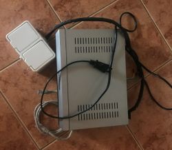
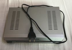
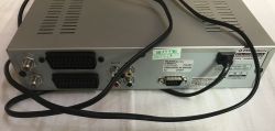
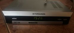
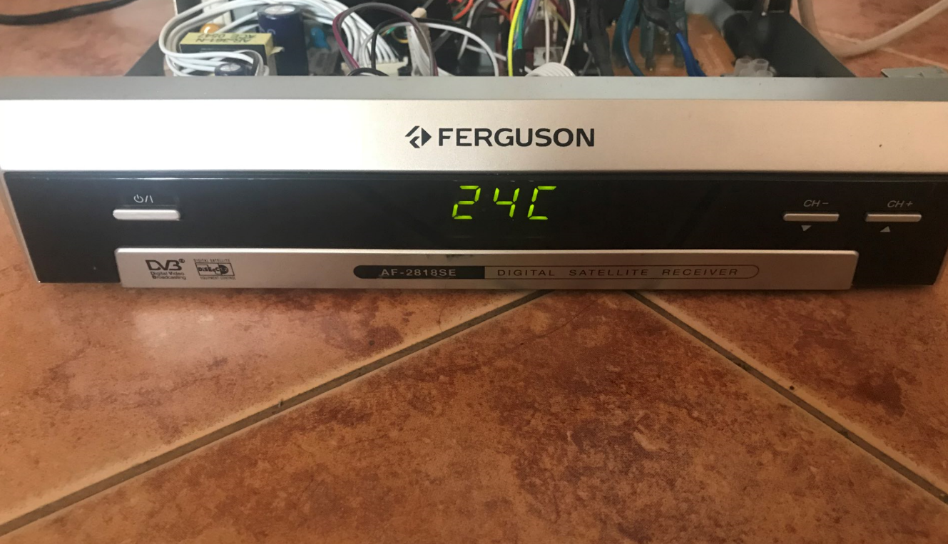
 Today I will present to you my network relay driver/timer/thermometer realised in a housing from a Ferguson AF 2818 SE satellite receiver based on my runner board under PIC18F67J60.
Project idea I've been experimenting with internet control for quite some time and already had my own board with PIC18F67J60 prepared for this purpose, but only recently fell into my hands satellite receiver Ferguson AF 2818 SE. Its housing immediately appealed to me - small, handy, just right for use. After opening the whole thing, I saw that its power supply module also looks quite ok and provides the voltages I need (3.3V, 7V and 12V).
I decided to use the housing and power supply from this Ferguson to make a simple device to control several receivers with mains voltage via the internet. Initially the project was intended to be quite modest, but over time it has grown and at this point the whole thing includes:
-
PIC18F67J60 along with communication
Ethernet -.
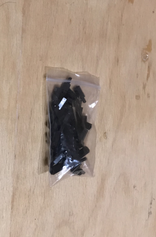
4 relays (you can easily increase the number)
-.
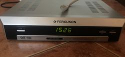
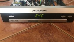
four-digit display (the same original as was in the tuner; in the role of clock and temperature display; controlled by
MM74HC164N )
-.
RTCC clock MCP7940 together with quartz and battery (to keep the time when all is disconnected from the mains)
- thermometer
TC74 - mains switch, fuse
- power supply (original from sat tuner)
- three buttons (original from tuner; not supported in code at the moment, but hardware connected)
- IR receiver (original from tuner; not supported in the code at the moment)
Here I will describe from the beginning how the project was created and at the end I will put the related attachments (codes, PCB files)
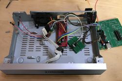
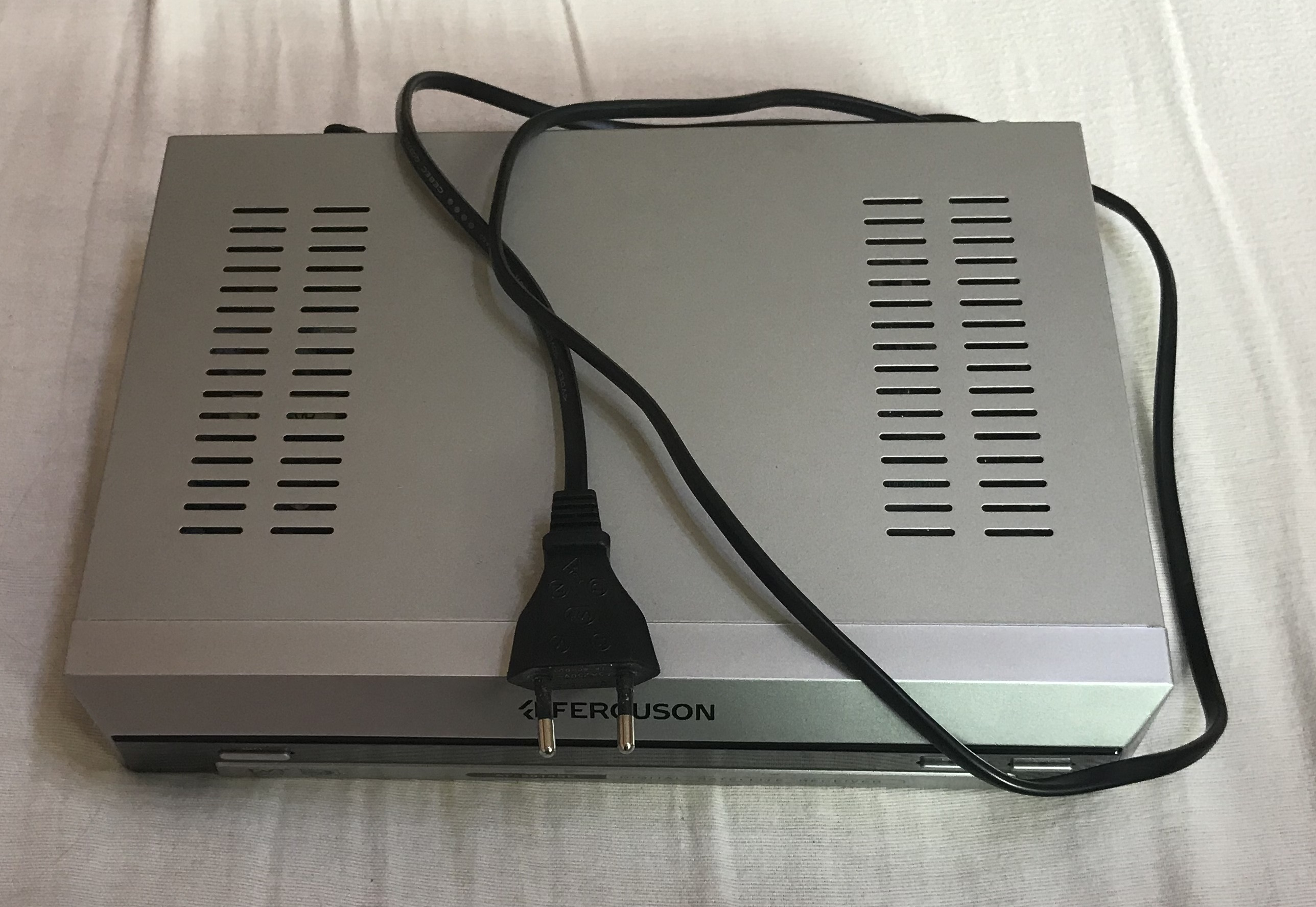
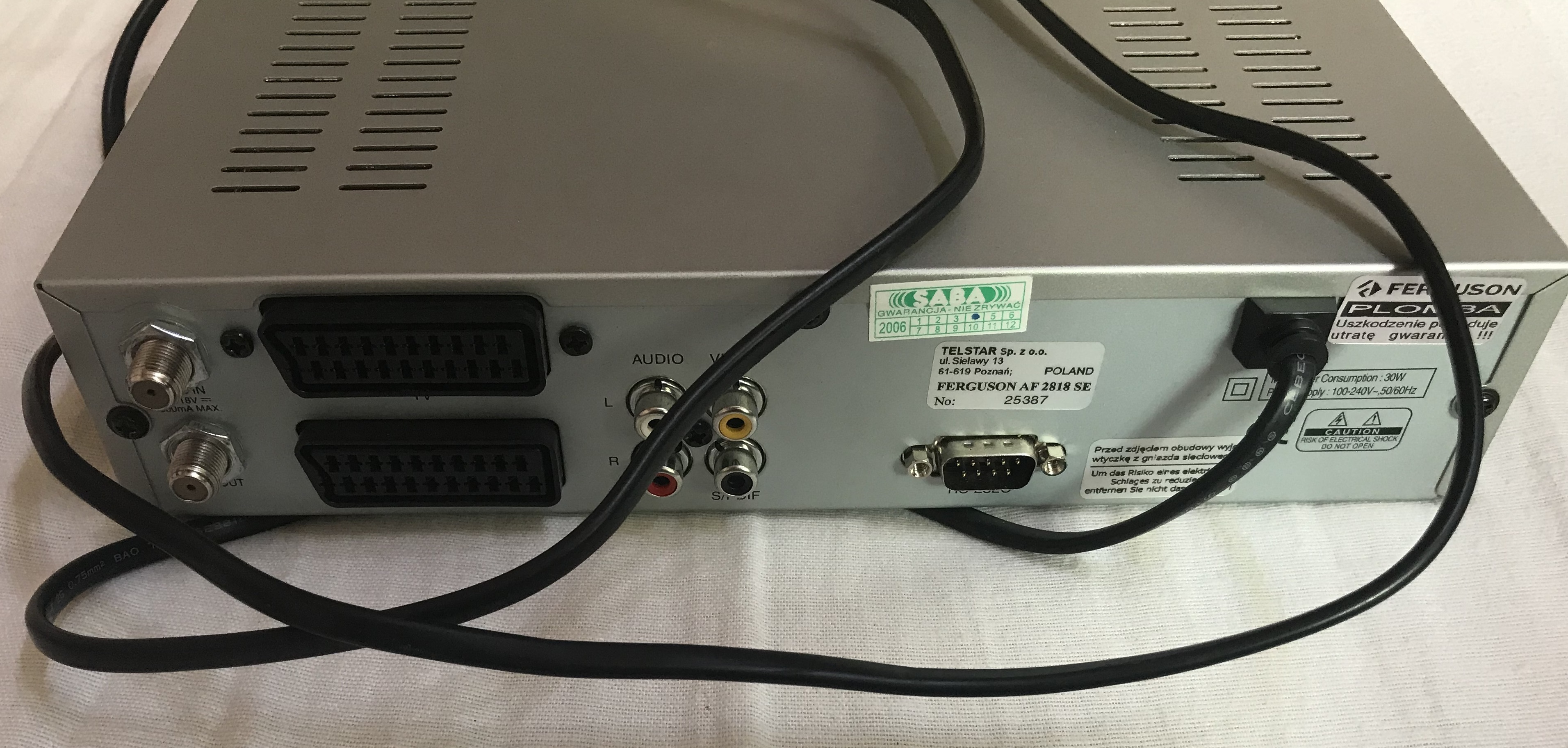
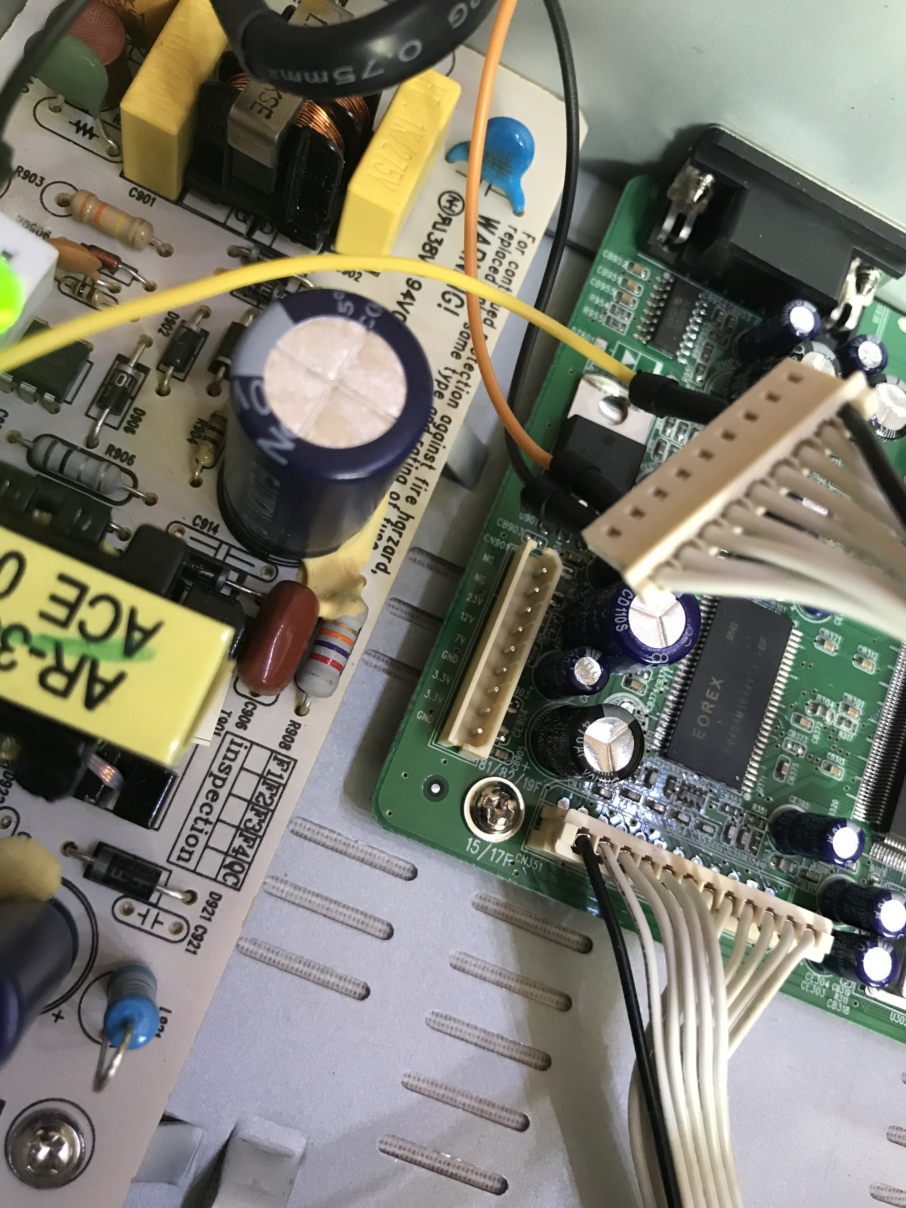
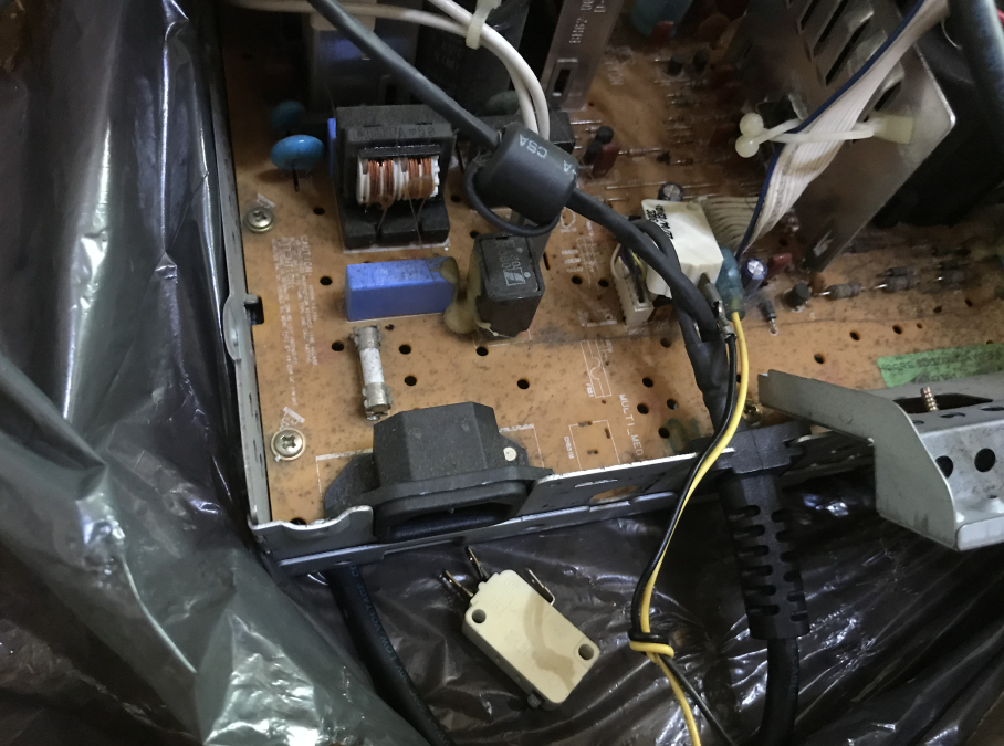
Beginning of the project - disassembling the tuner So we start from the beginning. The start was to disassemble the tuner and see what's inside - I hoped to be able to use at least the power supply module, and I did.
To start with, I checked that the power supply would boot on its own without the motherboard. It booted up without a problem (as most of these types of devices do, by the way - switching power supplies from them are very easy to reuse in various projects).
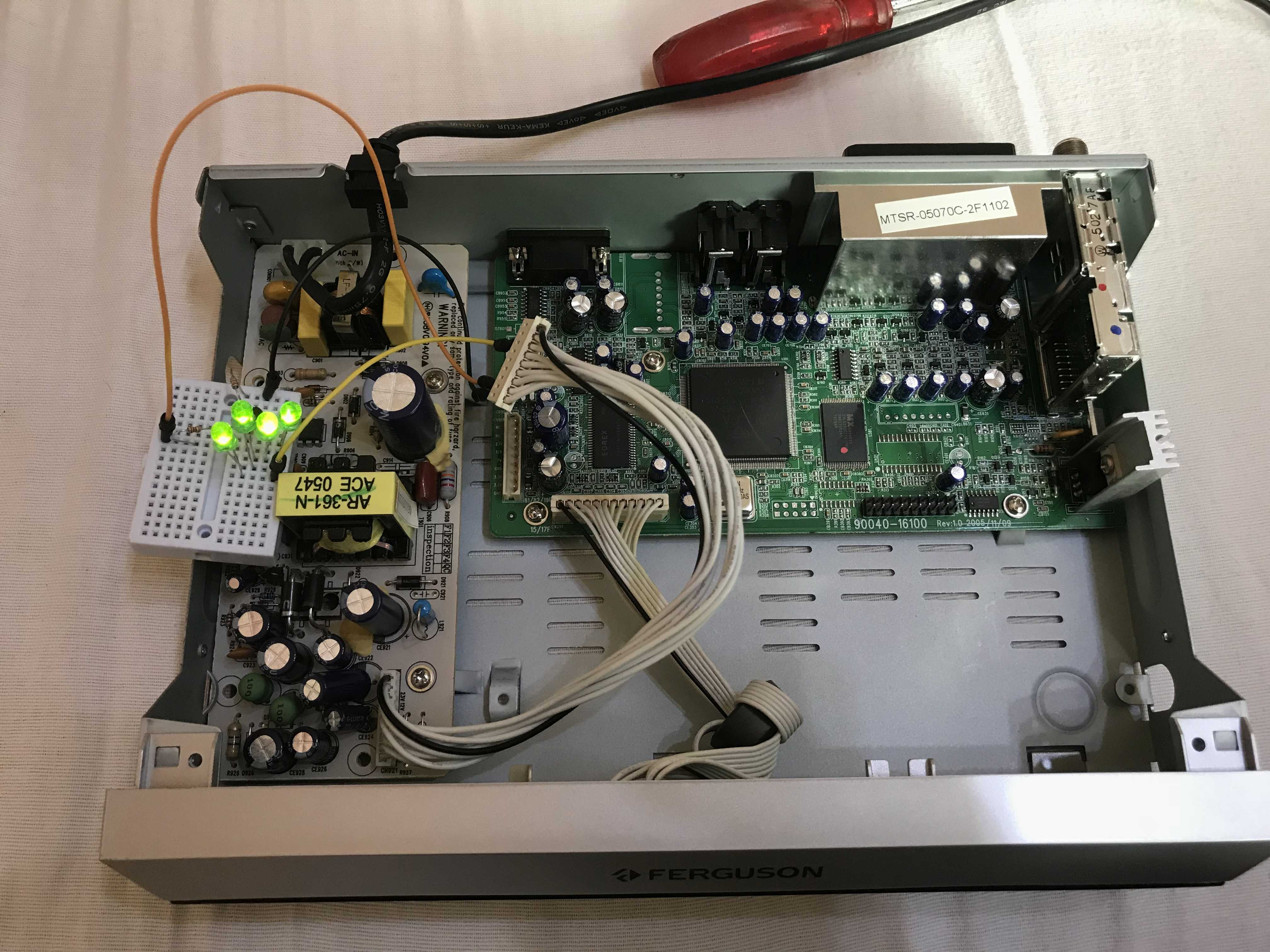
What's more, I saw that even the voltages from the power supply are listed on the PCB! All clear and readable - as it should be. The exact voltages, on the other hand, I didn't check, because I was going to use the 7805 (5V) and TC1264 (LDO 3.3V, already on the board with the PIC):

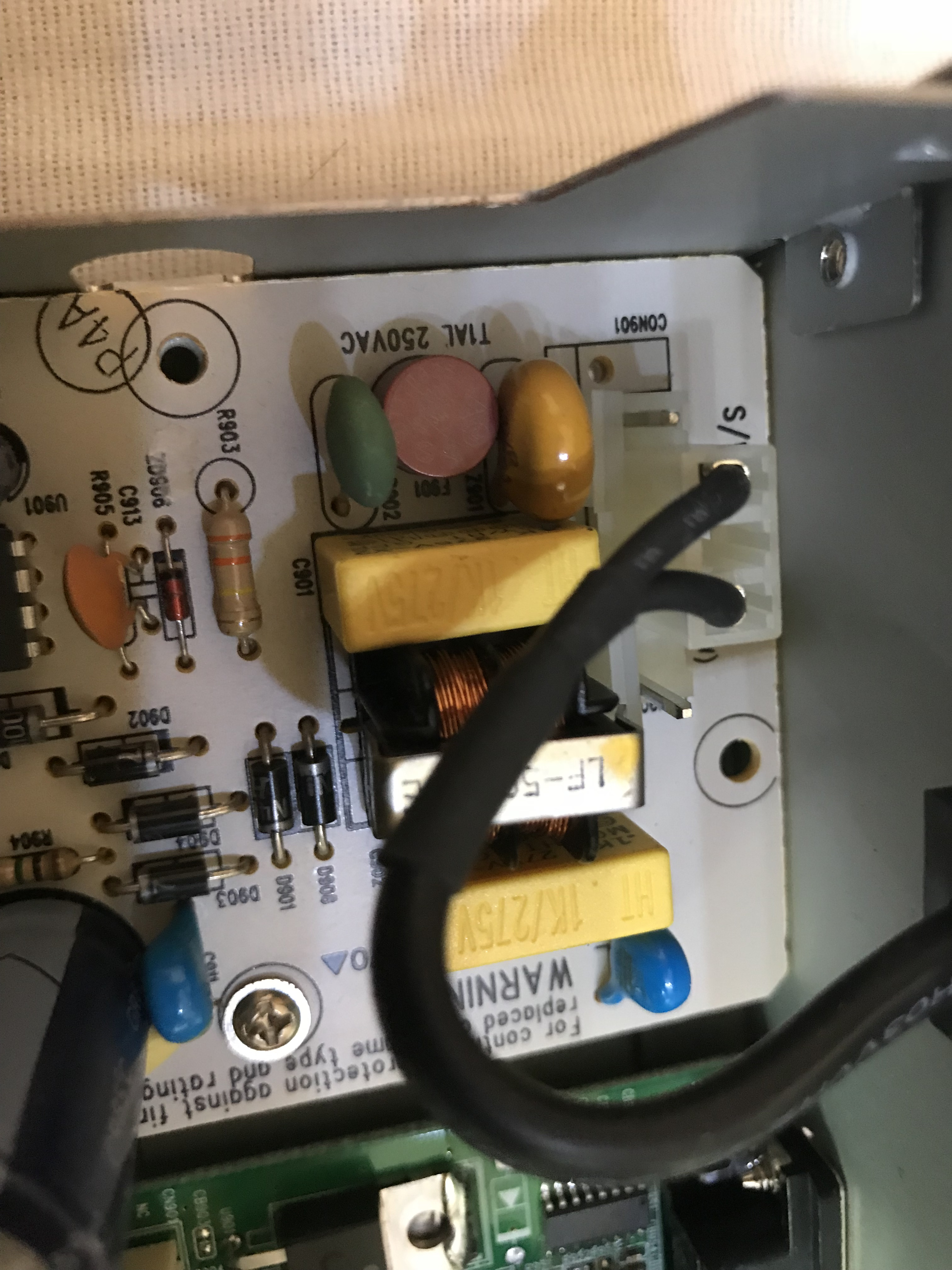
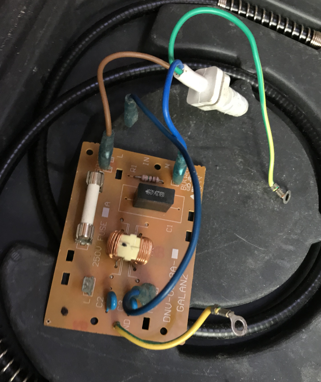
I also noticed an interesting way in which the mains cable was connected to the power supply board:
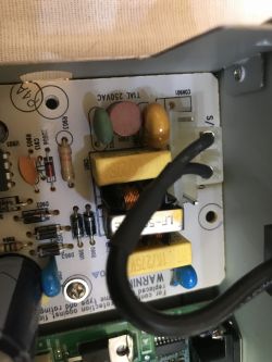
I guess the power supply board was intended for a slightly more elaborate model, but then someone decided to cut costs and did it the way he did. Well, I often come across such 'flowers'.
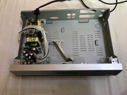
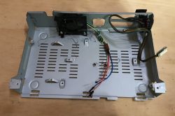
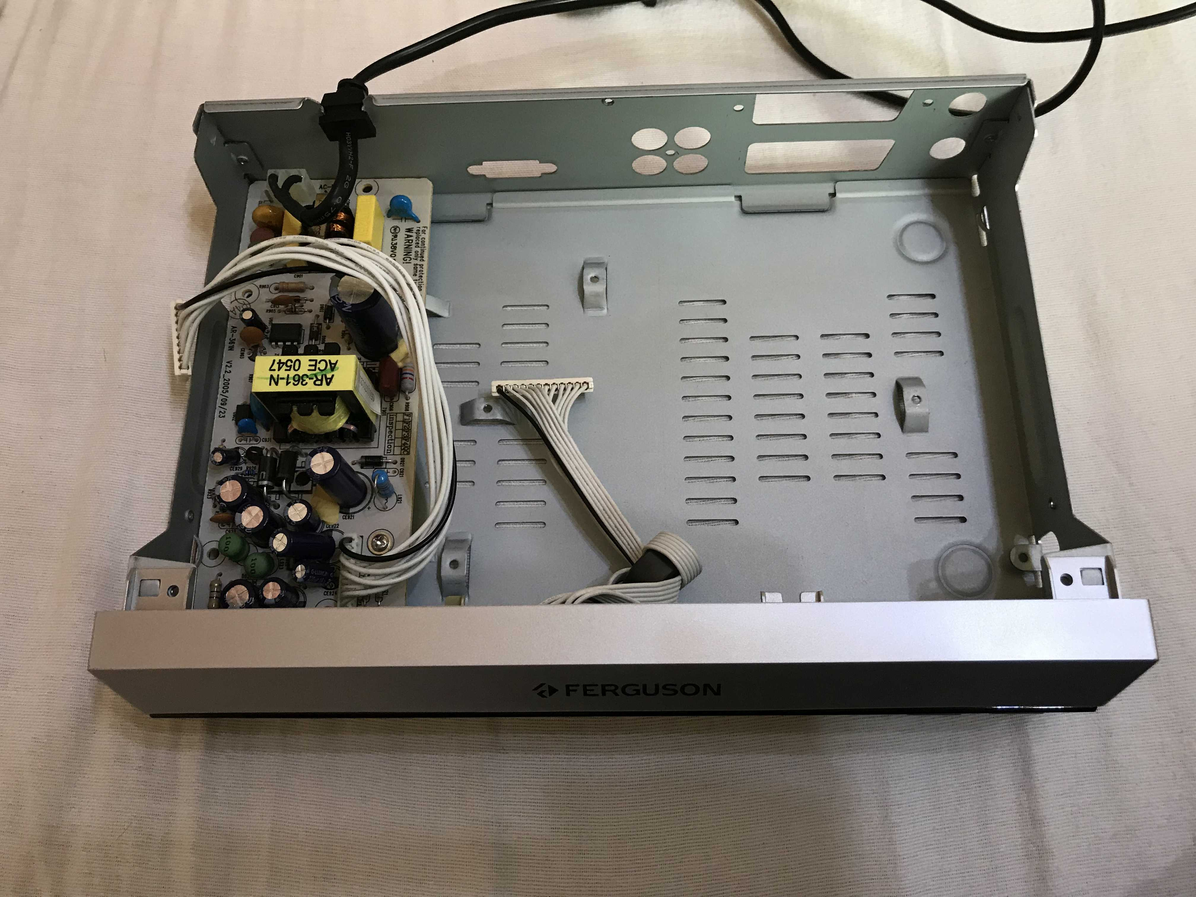
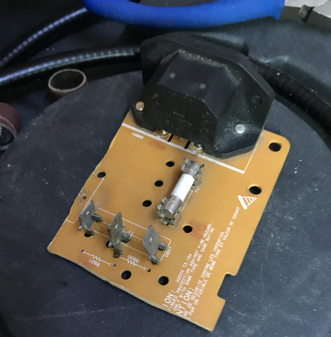
And this is how the tuner looked like after deleting what was unnecessary from it:
 Unexpected extension to the project -. using the front panel from the sat tuner
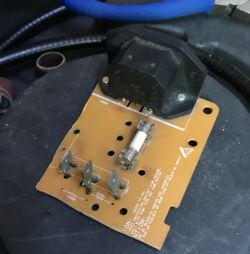
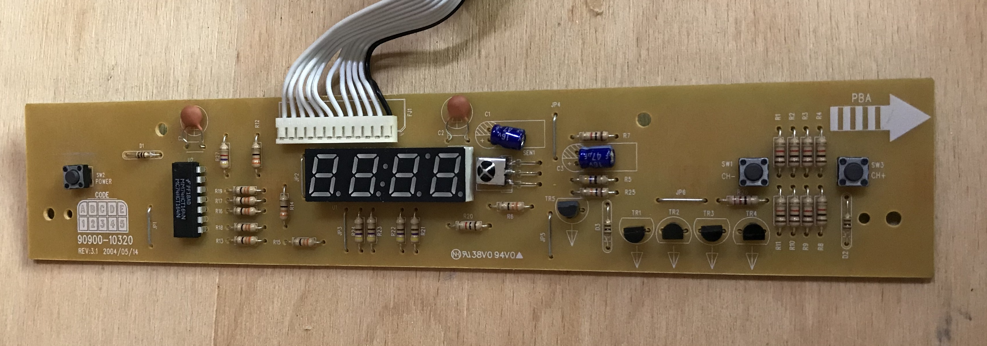
 It wasn't originally in the plans, But after disassembling the whole thing, I realised that the front plate from the tuner seems to be quite simply realised.
Here are pictures of it, just after dismantling:

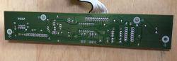
On this board there are:
- three buttons (originally on/off switch and channel switching front to back)
- IR receiver
- 7segment 4-digit LIN-39422g display
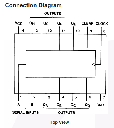
All controlled by one IC -
MM74HC164N . It particularly stands out in the picture because it is the only chip there in a DIP enclosure.
MM74HC164N is a Serial-in/Parallel-out Shift Register.
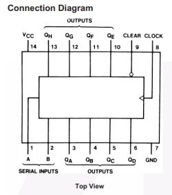
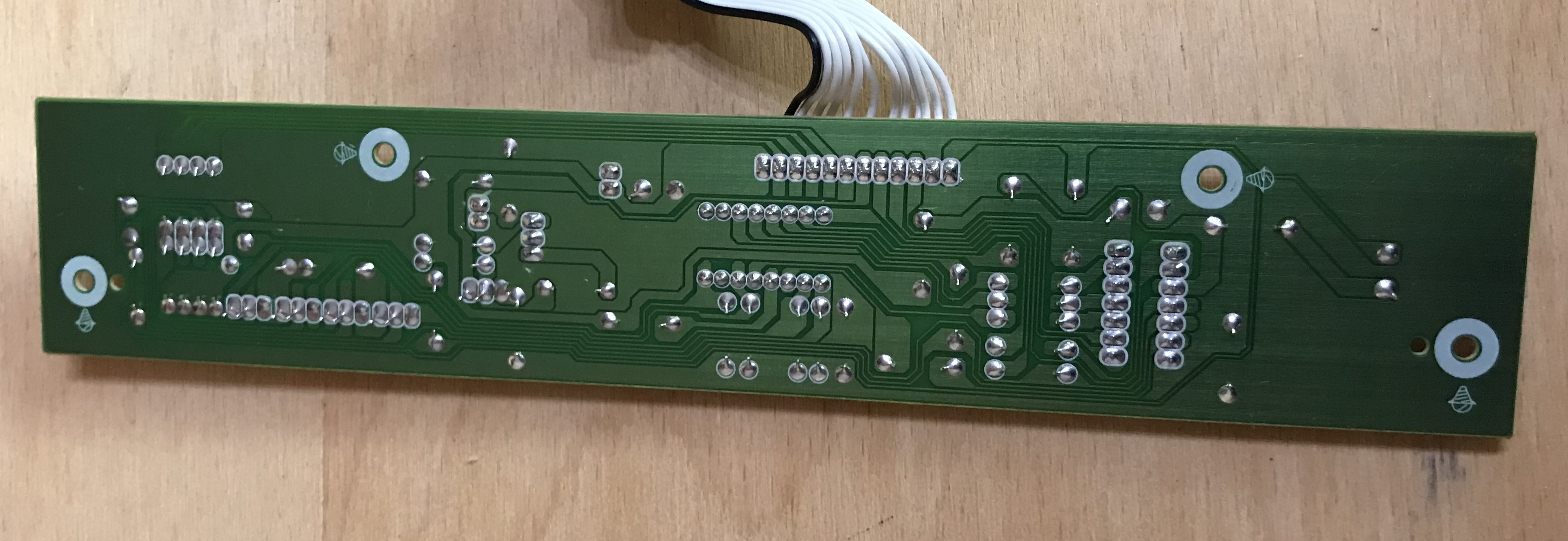
I removed this panel and looked at it carefully. It was connected to the rest of the unit with only one tape. I couldn't find a schematic of this board on the web, so I quickly made a breakdown of the connections and pins. I will paste it here as it was created:
Quote:
Display LIN-39422g , MM74HC164N
STRAND 1 - three-button mass.
STRIP 2 - ground (capacitors from VDD)
STRIP 3 - pin 9 clear MM74HC164N
STRIP 4 - pin 8 clock MM74HC164N
STRAND 5 - pins 1,2 Serial Inputs MM74HC164Na
STRAND 6 - collector of transistor from IR receiver (its emitter is to ground)
BAND 7 - ground (same as BAND 2)
BAND 8 - transistor base through resistor (this base also has pullup to VDD); its emitter is connected to 7seg
BAND 9 - transistor base through resistor (this base also has pullup to VDD); its emitter is connected to 7seg
BAND 10 - transistor base through resistor (this base also has pullup to VDD); its emitter is connected to 7seg
TABLE 11 - transistor base through resistor (this base also has pullup to VDD); its emitter is connected to 7seg
TABLE 12 - last - VDD - VDD MM74HC164N; via 20 ohm resistor also collectors of 4-transistors
D1, D2, D3 - resistors from buttons, 100ohm
Buttons go to PINs MM74HC164N : 3, 4, 5
MM74HC164N :
1 and 2 - Tape 5
3 - button + resistor and then 7-seg
4 - button + resistor and then 7-seg
5 - button + resistor and then 7-seg
6 - resistor, and then 7-seg
8 - clock
9 - clear
10 - resistor and then 7-seg
11 - resistor and then 7-seg
12 - resistor and then 7-seg
13 - resistor and then 7-seg
Additionally I consulted the catalogue note
MM74HC164N :
This was enough for me to later write support for this panel for my PIC from 0. This enhanced the project with the ability to simply display information.
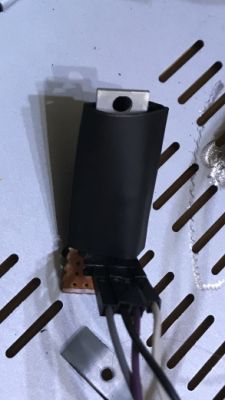
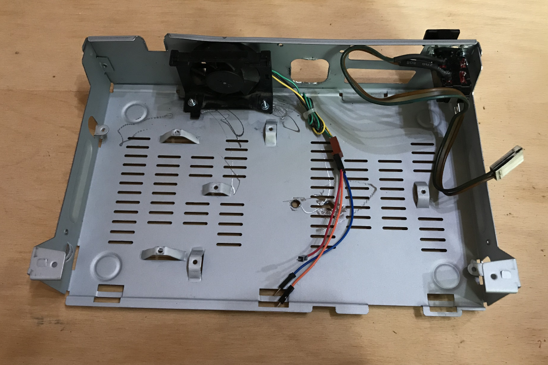
First modifications First I added a small fan and a mains ON/OFF switch, all taken from a drawer/electronic scrap.
I insulated the wires to the switch thoroughly with heat shrink sleeves.
The idea for the switch itself came from two reasons:
- originally the tuner, when connected to the mains, was in stand by all the time and it was not possible to switch it off at all
- the power supply board from the tuner already had a ready-made, derived connector, it was just asking to use it
There were also problems with the mechanical assembly of the parts (this can also be seen from the photo), because I assumed that everything would be fixed with screws, but nevertheless finally managed to make the necessary holes.
When assembling I used, among other things, plastic spacers:
I chose plastic ones, as these do not conduct electricity. During construction I attached great importance to making solid connections and careful insulation.
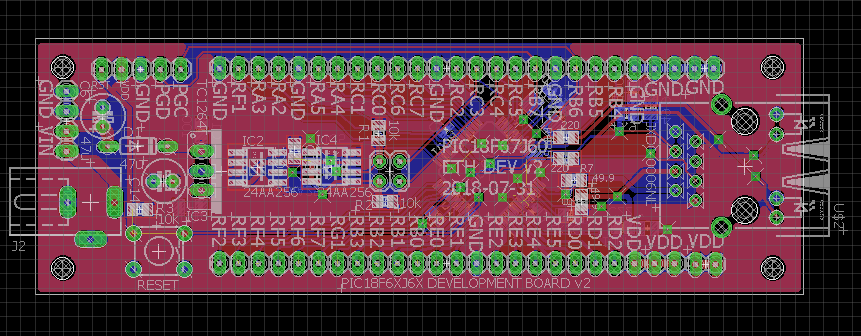
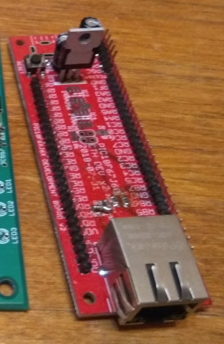
Then I reached for my PIC and Ethernet communication board (PIC18F67J60 development board of my project):
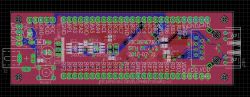
It is on this board that the PIC18F67J60 with Ethernet communication is located, which will control the whole construction.

Then I have already fixed it and made the first tests of programming the whole thing with my PICKIT2 clone.
.
This large green board outside the device casing is my PICKIT2 clone - a PIC programmer on USB. Through it I upload the batch to the PIC18F67J60, which is on the red board.
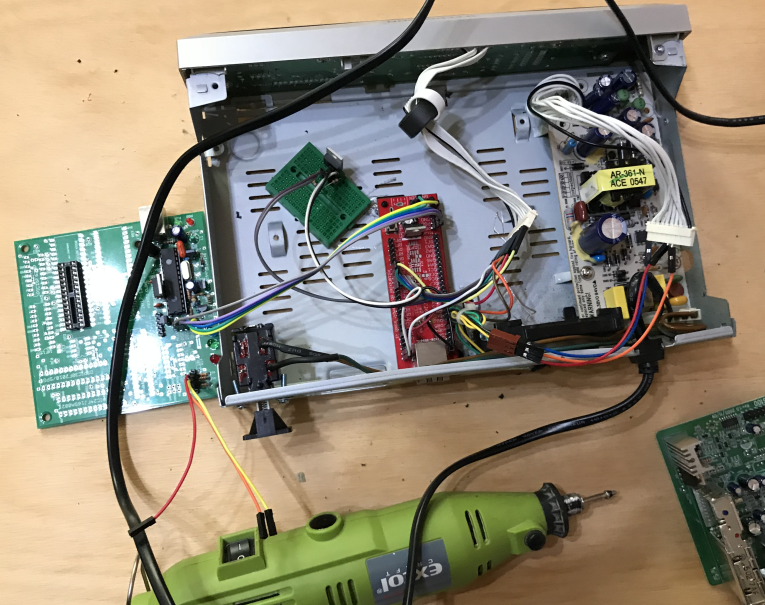
Same as above, but after putting the power supply module back in:

Then I decided to use the connector from the power supply (and a part of the PCB, because there are signed voltages there) and I prepared a small board on which I also put the 7805 on a heatsink (because I just missed 5V from the power supply):
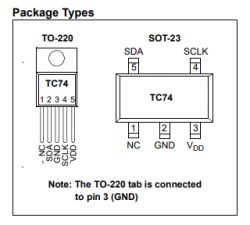
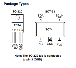
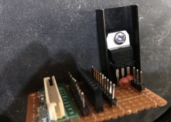 Termometer TC74 (on I2C bus)
 Temperature measurement was not in the plans, But if it was possible to get the display working then why not? I chose a thermometer that is quite simple to use (TC74) and quickly wrote its support in C.
This thermometer returns the temperature as an integer, but in this application this is not a problem. Communication with it is realised via I2C.
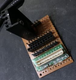
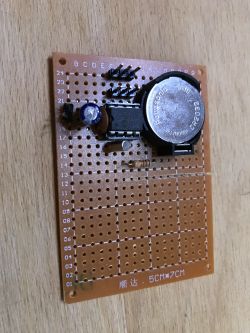
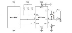
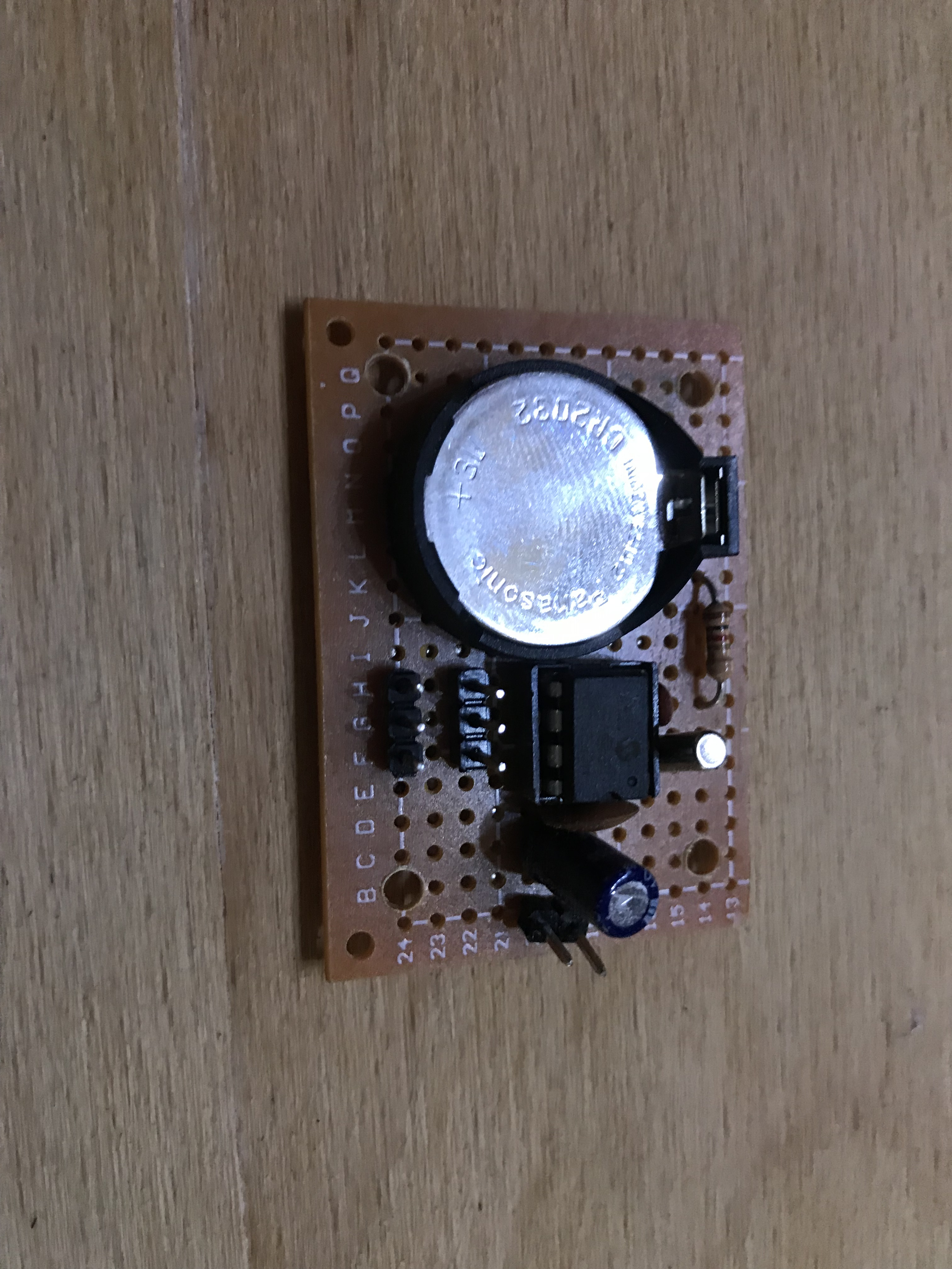
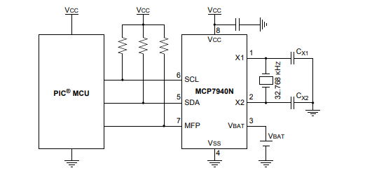
 Module RTCC MCP7940 (on bus I2C)
 The idea came about spontaneously (just after I managed to get the front panel display working,) So the RTCC is on a prototype board. The chip used is the MCP7940, the schematic as in its catalogue note. There is also a CR3032 battery on the board to keep time when the device is powered off.
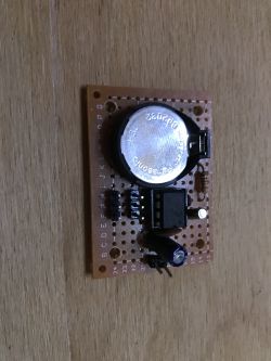
I connected the module itself to the I2C bus, where the thermometer was already on. This is not a problem, these chips have different addresses.
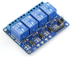
Transmitters I used a ready-made module with four relays purchased in china for the project, But in principle there is no limit to the number of them here. You might think they are limited by the number of pins - but nothing could be further from the truth, operating a port expander (MCP23017 for example) is very simple.
In order to connect the relays to the network, I decided once again to use a ready-made module from scrap (or actually make myself a module by cutting it out of the board). The photo shows the motherboard from a CRT monitor from which I took the connector and its whole section for the fuse:

I also used the connectors inserted from a board from an old microwave oven:

This is what the finished module looks like (prepared to be attached via plastic spacers to the underside of the case and via screws on the power connector to the back of the case):
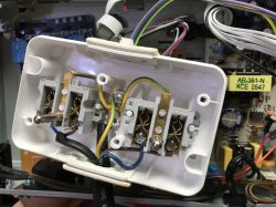
Then I decided that for the time being I only needed to control two devices at 230V so I converted a double mains socket accordingly, with the idea that it would be connected to the relays.
Five wires are pulled to this socket (ground is common). Everything is well insulated, also with the help of heat shrink sleeves.
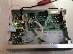
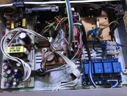
This is how the whole thing looks like after adding the relays and the mains socket module inside:

And the finished whole thing - still with the ICSP wires connected from the programmer.
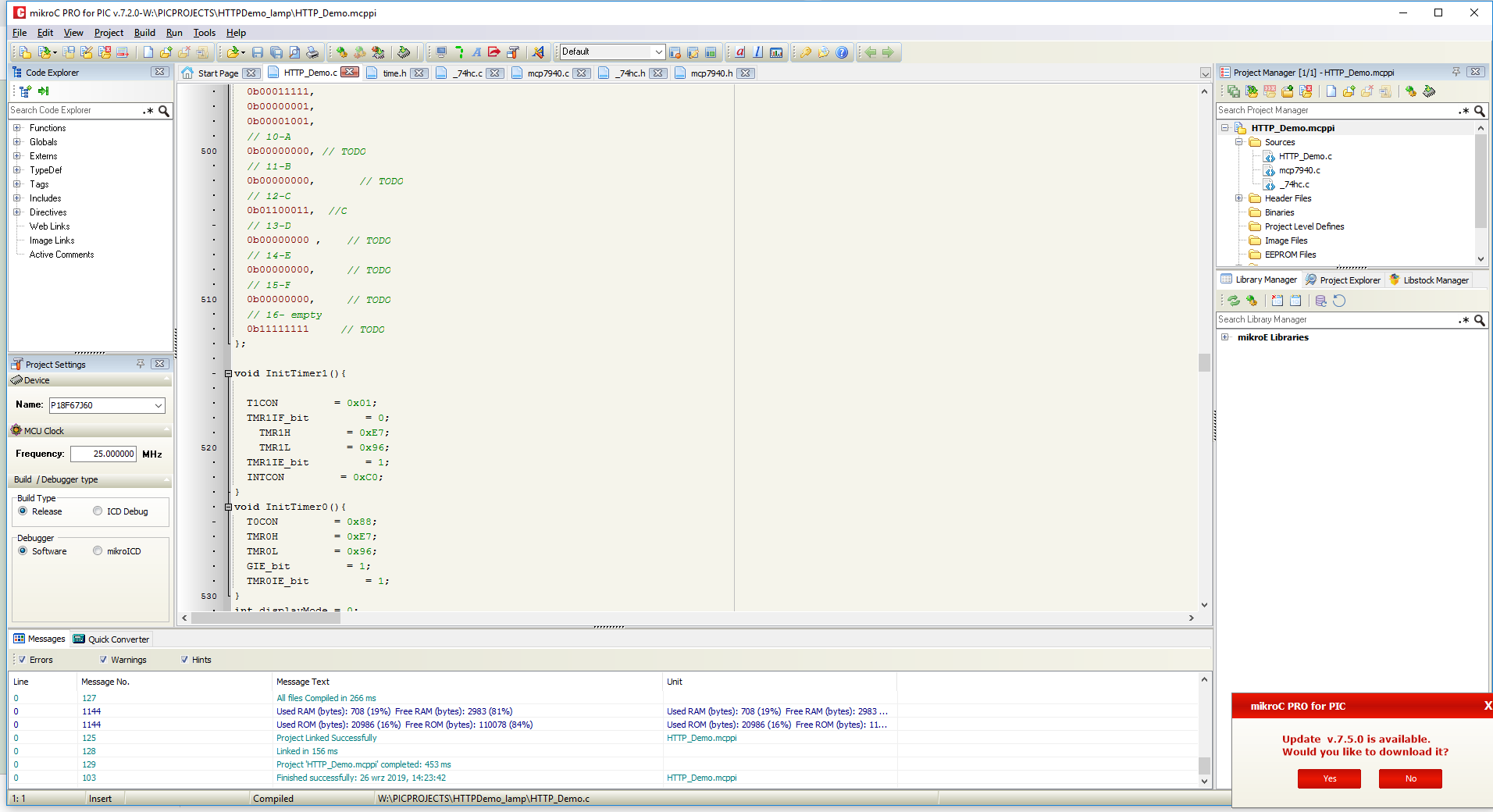
 Firmware on the PIC
 Firmware was written in MikroC PRO for PIC based on HttpDemo for PIC18F67J60. I added support for the I2C bus (for thermometer and RTCC), 74HC shift register, software PWM (not used in this project) and the possibility to control the relays and the aforementioned PWM via a web page.

The code is not final, it is not cleaned, I only make it available to those interested fully at their responsibility.
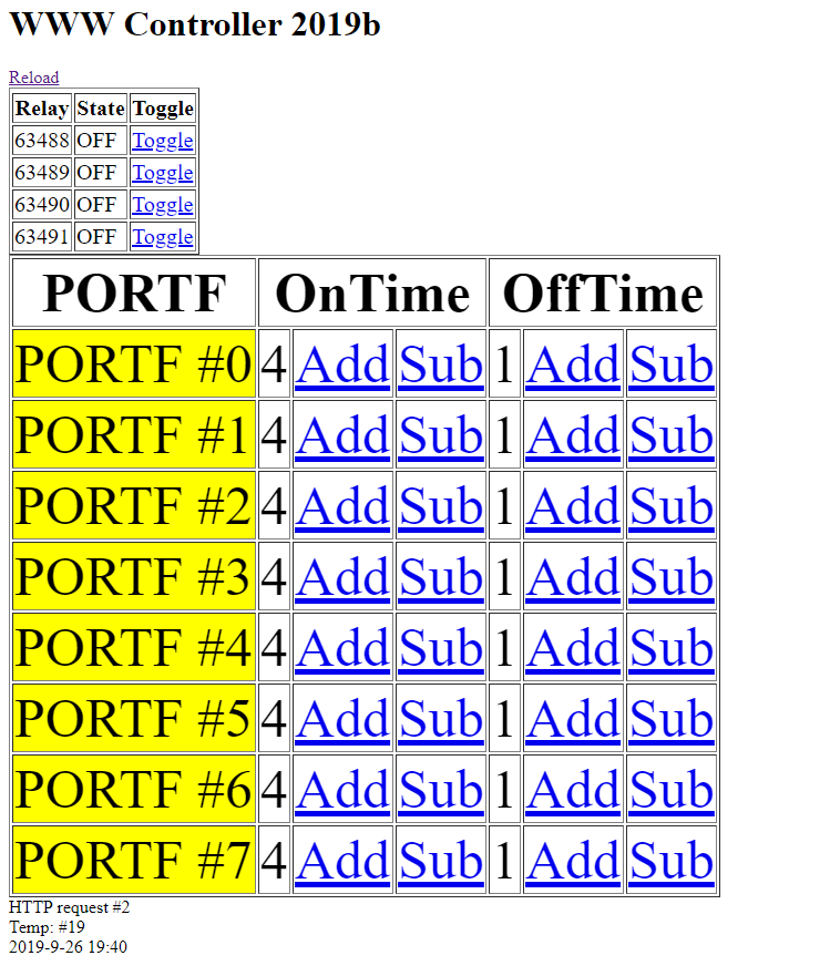
The test website at the moment looks like this:
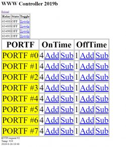
On the website there is an interface for:
- on/off control of the relays
- software PWM control on the free pins of the PIC (
I don't use this at the moment, but it's intended for brightness control of LED lighting )
- additionally the timing information from the RTCC and temperature are output.
The whole lighting control could also be separated on UDP and controlled e.g. from an Android phone app completely bypassing the website.
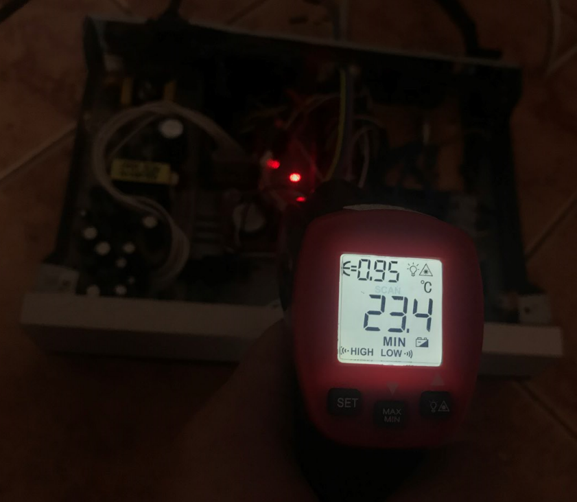
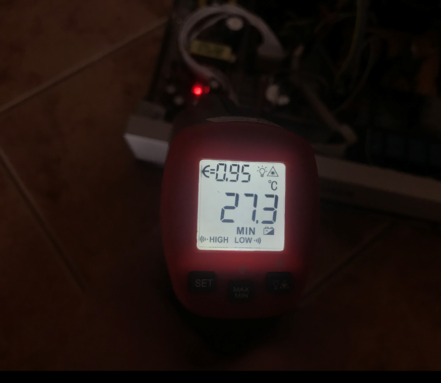
Final test of the power supply Finally, I still wanted to check, whether the power supply can handle it and whether nothing in the circuit heats up excessively. I left the whole thing switched on for half a day and then (after temporary disconnection from the mains) I removed the applied casing and checked the temperatures with my pyrometer:
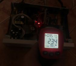

Luckily I didn't note any excessive heating, so the device is ready for operation.
Then I still checked that the battery was holding time and that the temperature results were reasonable and for my taste everything was fine:
 Further development of the project
 - At this point I have closed the project and consider it finished, but of course a lot could still be added to it. Among other things you could still:
- add support for buttons on the front panel (they are connected, just give them some function)
- add time synchronisation with the internet via UDP
- add remote control (there is an IR receiver on the front panel, you just need to connect the cable and program the RC decoding)
- solve the problem of unnecessary holes on the back of the case (eg. with the help of a laminate board)
Attachments Project in MicroC (web page and organisation of everything, additionally PWM code not used here; timer 1 is used for software PWM, timer 0 for display refresh; based on HttpDemo from MikroC):
HTTPDemo_l...190926.zip (260.97 kB)You must be logged in to download this attachment. MCP7940N RTCC support code over I2C:
mcp794..zip (1.6 kB)You must be logged in to download this attachment. Sliding register support code 74HC:
_74hc.zip (685 bytes)You must be logged in to download this attachment. Gerber of Ethernet controller:
PicEthV...zip (140.84 kB)You must be logged in to download this attachment. Catalogue notes of components used:

 .
.

 Termometer TC74 (on I2C bus)
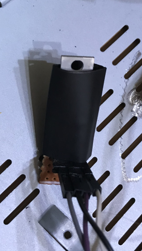

 I connected the module itself to the I2C bus, where the thermometer was already on. This is not a problem, these chips have different addresses.


Comments
Cool design. Plus for the careful craftsmanship and use of scrap metal. Unfortunately, I have the impression that it's form over content. A similar device can be made on an ESP32, some relays and a USB... [Read more]
You are 100% right that most things can be done on off-the-shelf stuff like the Arduino, but I'm just trying to do everything from scratch as much as possible (this board with the PIC18F67J60 is also mine,... [Read more]
For this, of course, a big plus. I'm not keen on Arduino-like solutions either, although I do use them sometimes. I don't embrace PICs but I think you can squeeze quite a lot out of it. I rather meant... [Read more]
Depends on what exactly I want to control, because if it's going to be some Christmas lights on a segment, window or Christmas tree then it's rather enough as it is. More to the point here would be... [Read more]
Big kudos to you for feeling the need to have such a device, you created it yourself, bravo for that. The description is also nicely done, you tried to accurately present what you have done. But as for... [Read more]
To paraphrase your statement: We have too many "programmers" who try to rewrite the world from scratch instead of intelligently using proven solutions. As a colleague has already mentioned, I also... [Read more]
The design is not perfect and was not intended to be so, and I admit that much can be criticised, but just what you pointed out has good justification :D I did so because, that there are signed voltages... [Read more]