Test and interior of the BW-SS3, a WiFi light switch from Blitzwolf
TL;DR
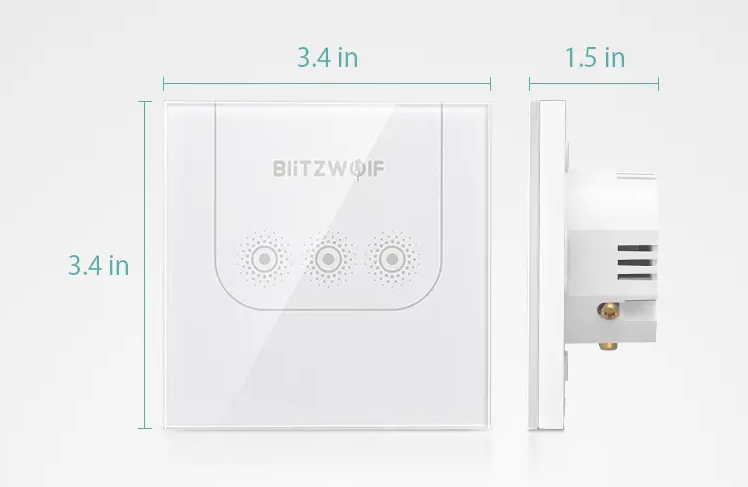
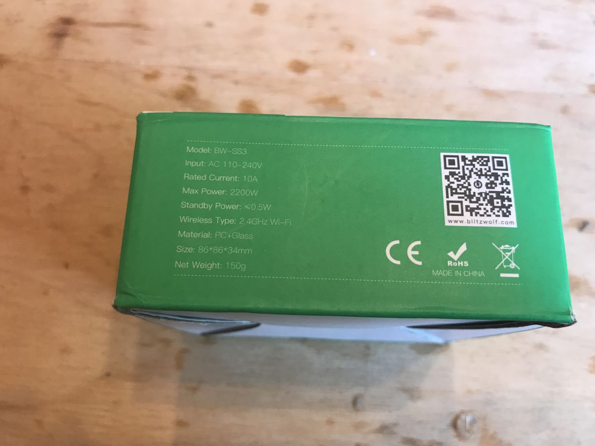
- The Blitzwolf BW-SS3 WiFi touch-sensitive wall switch is a double light switch for standard boxes, controlled locally or remotely through the Blitzwolf Android app.
- Inside, a TYWE3S Tuya module based on ESP8266, BS813A-1 touch controller, and PN8016 non-isolated supply drive the relays; one PCB is shared across switch variants.
- Measured mains consumption was 0.4W in standby, 1.0W with one relay on, and 1.7W with both relays on.
- Pairing succeeded on the first try, the switch worked without Wi‑Fi setup, and it fitted a classic can during a home trial.
- The 2x4 connector does not help with custom firmware uploads; only TX and RX are relevant, and Tasmota support is mentioned for later.
Summary generated by AI based on the discussion content.
 .
.
Hello my dears .
I'd like to invite you to my brief test and teardown of the 'smart' WiFi touch-sensitive light switch BW-SS3 from Blitzwolf. This switch allows us to control our lighting both normally and remotely via an Android app using the home WiFi network without the need to install additional devices and fits into a classic box.
Previous part - BW-SHP8 socket .
In the previous section, I described in detail another Blitzwolf product, namely the WiFi-controlled BW-SHP8 socket additionally offering electricity metering.
 .
.
The description is available here:
https://www.elektroda.pl/rtvforum/topic3687040.html#18652154
In the description I have also shown in detail the process of installing the Blitzwolf app on an Android phone, registering a free Blitzwolf account, etc. etc. and most of the information from the above topic also applies to the switch described here. So I won't describe it here a second time - I refer those interested to the previous topic.
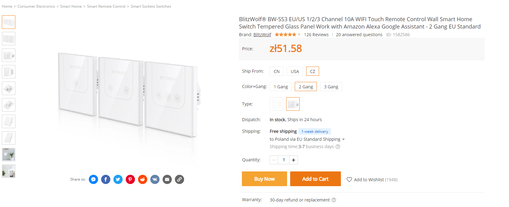
Purchase BW-SS3 switch .
I bought the product on the Banggood website for just over PLN50, I chose to have it shipped there from the Czech Republic.
 .
.
 .
.
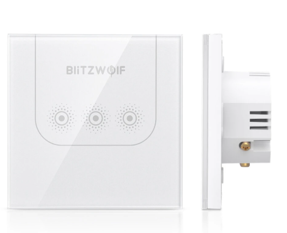
The BW-SS3 switch is available in three versions - one, two, or three switches in one housing:
 .
.
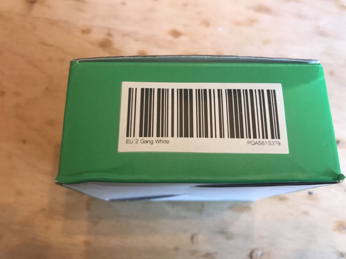
I chose version two (double switch).
The size of the BW-SS3 is compatible with a standard can, so there should be no problem attaching it:
 .
.
The package came quite quickly, especially as it was sent from the Czech Republic and not China.
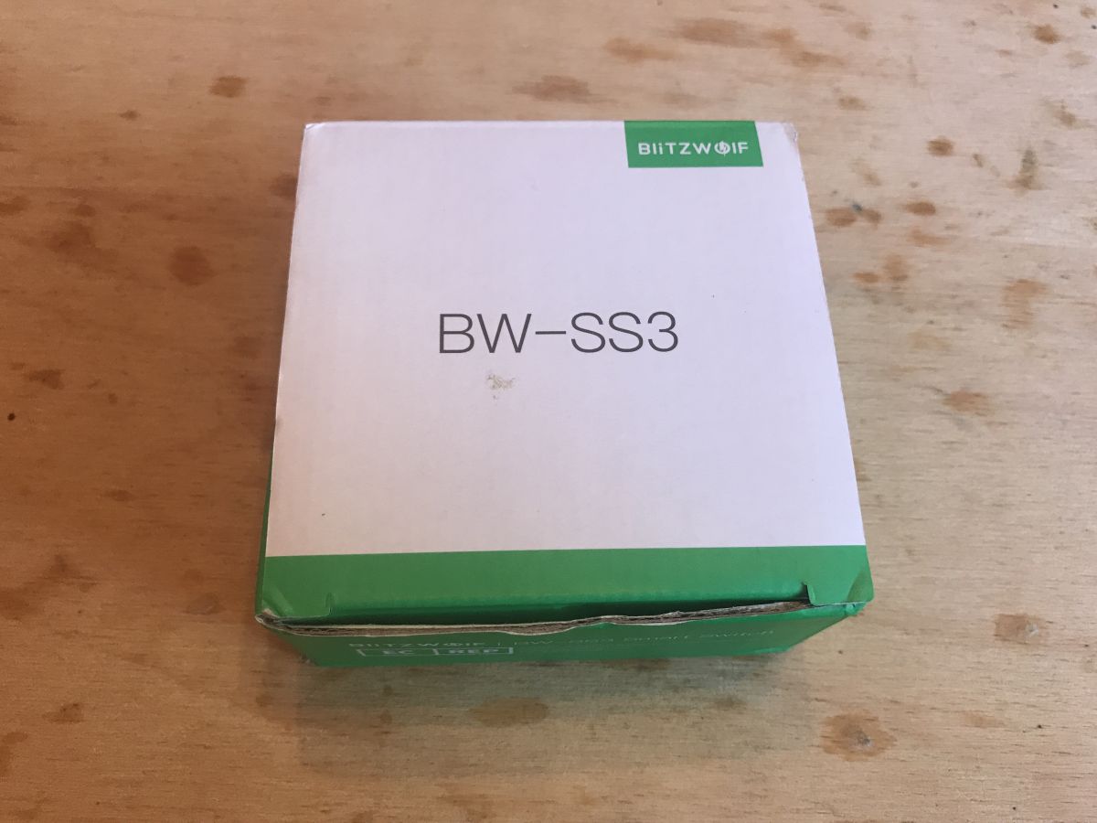
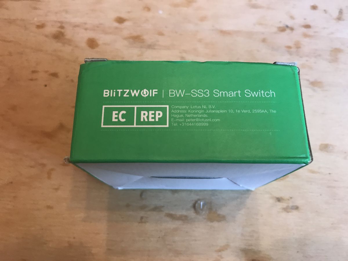
The product came in the original box:
 .
.
Included was a well protected switch along with a leaflet and instructions:
 .
.
Running the BW-SS3 switch .
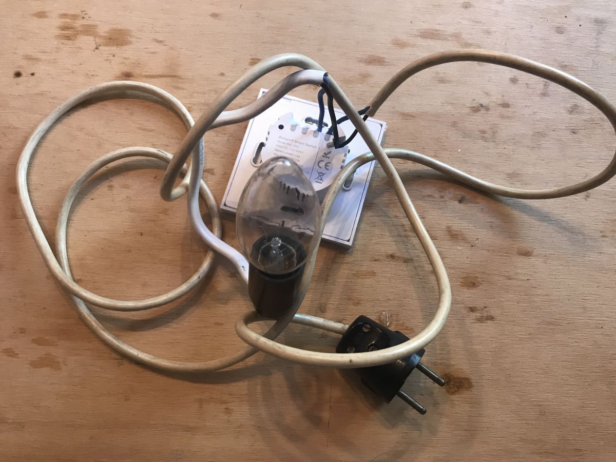
I ran the switch loose to be able to comfortably check how it works and take measurements.
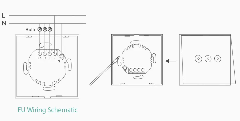
I made the connections according to the diagram:
 .
.
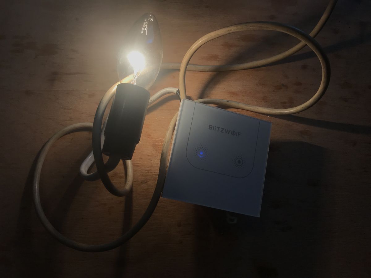
My connections (I only used one bulb):
 .
.
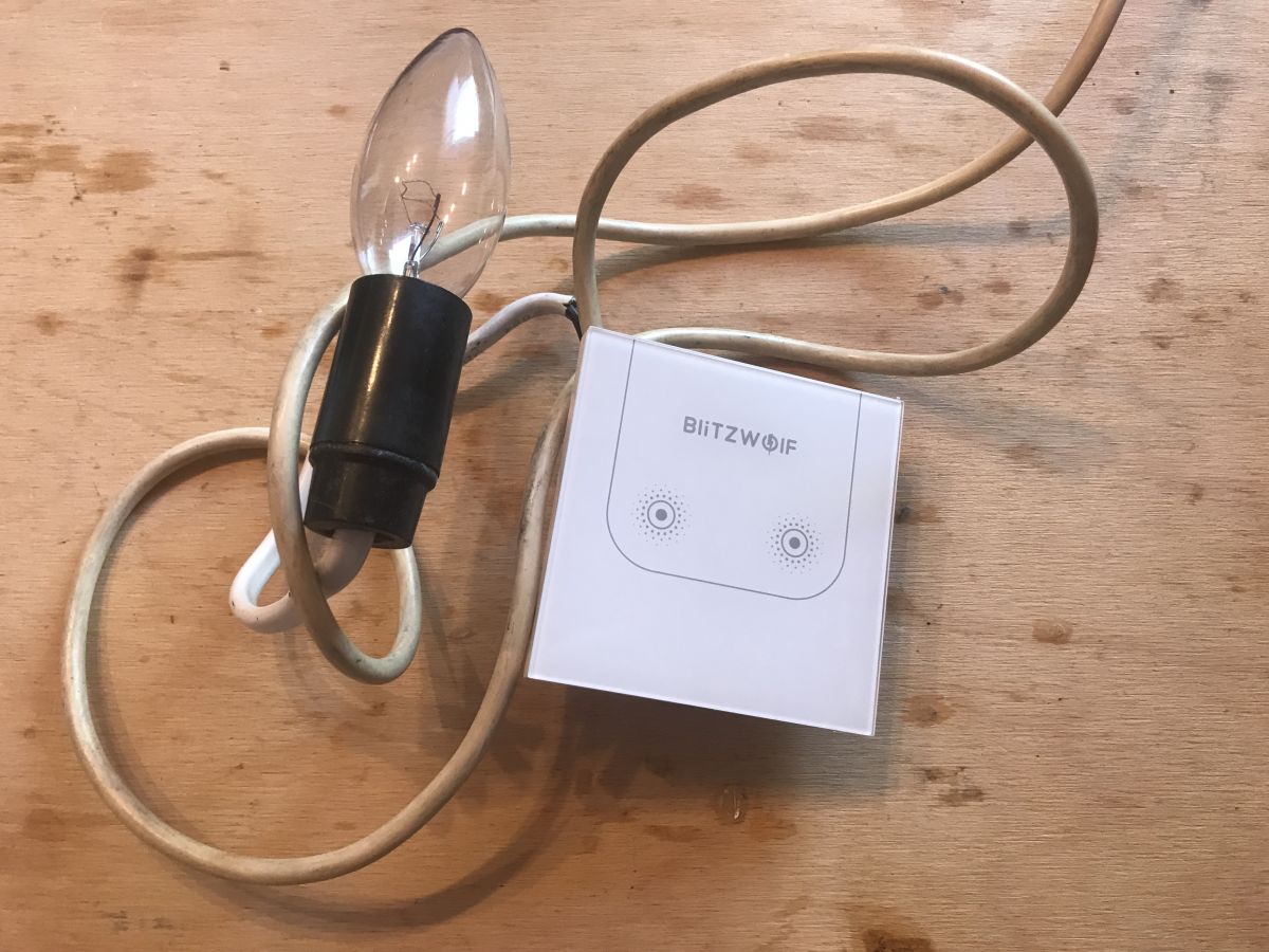
The switch was already functional without pairing it with a Blitzwolf phone/account via WiFi:
 .
.
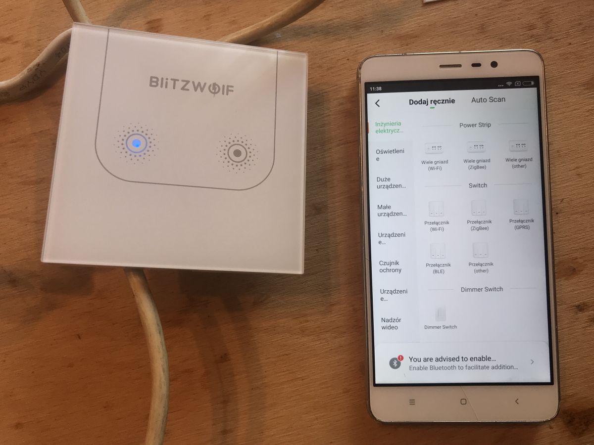
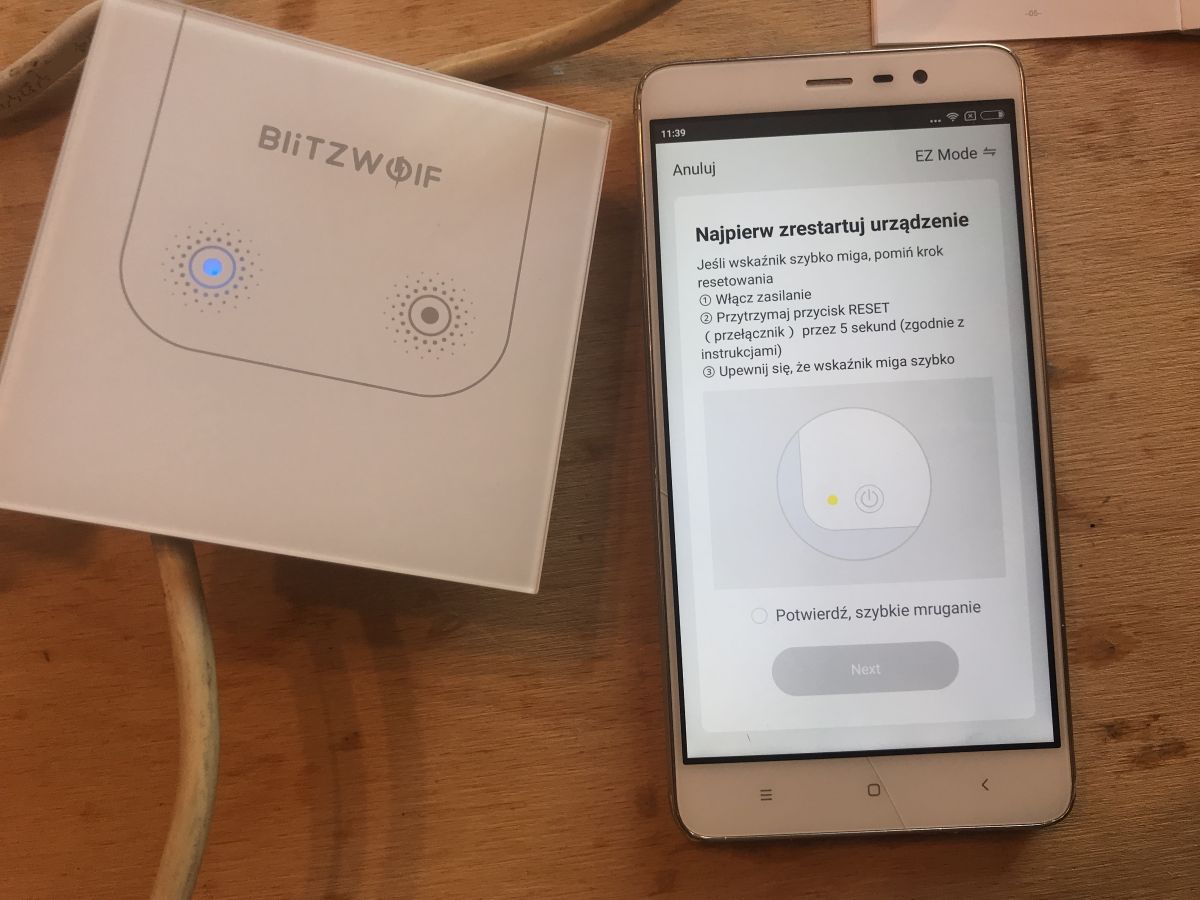
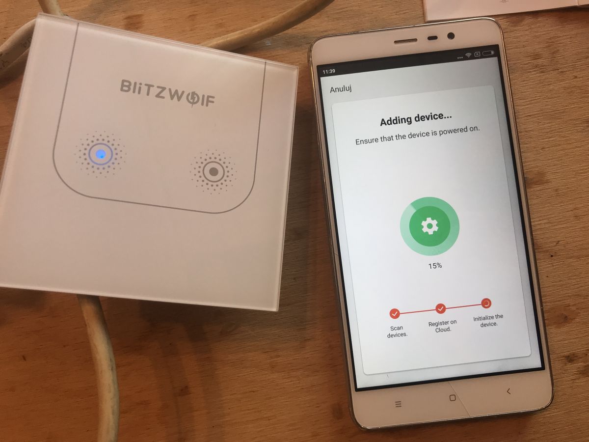
I started the pairing mode as instructed, that is, by pressing the first touch button for a long time until it starts flashing. In the Blitzwolf app (its installation is described in the previous topic in this series ), I chose to add manually and selected "Switch/WiFi Switch" as the device type:
 .
.
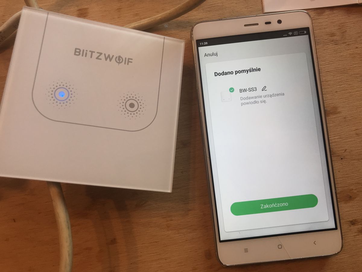
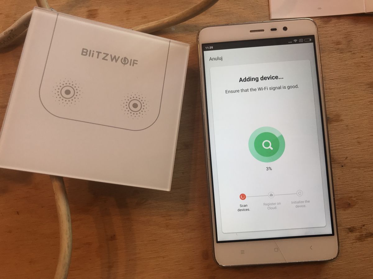
The pairing was successful the first time:
 .
.
 .
.
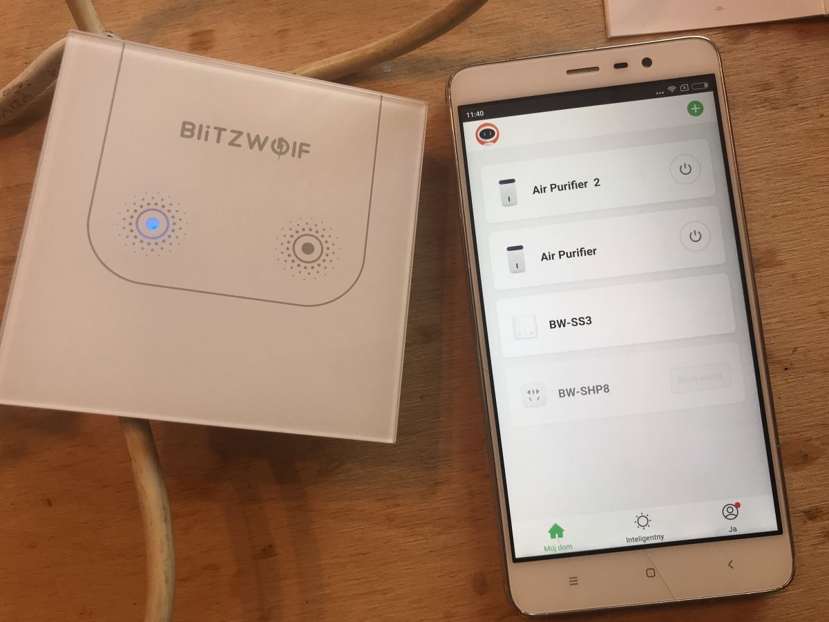
The switch has since appeared in my list of devices in the Blitzwolf app:
 .
.
(My list also shows the BW-SHP8 from the previous topic and two 'Air Purifiers' which I haven't described here, but may describe soon)
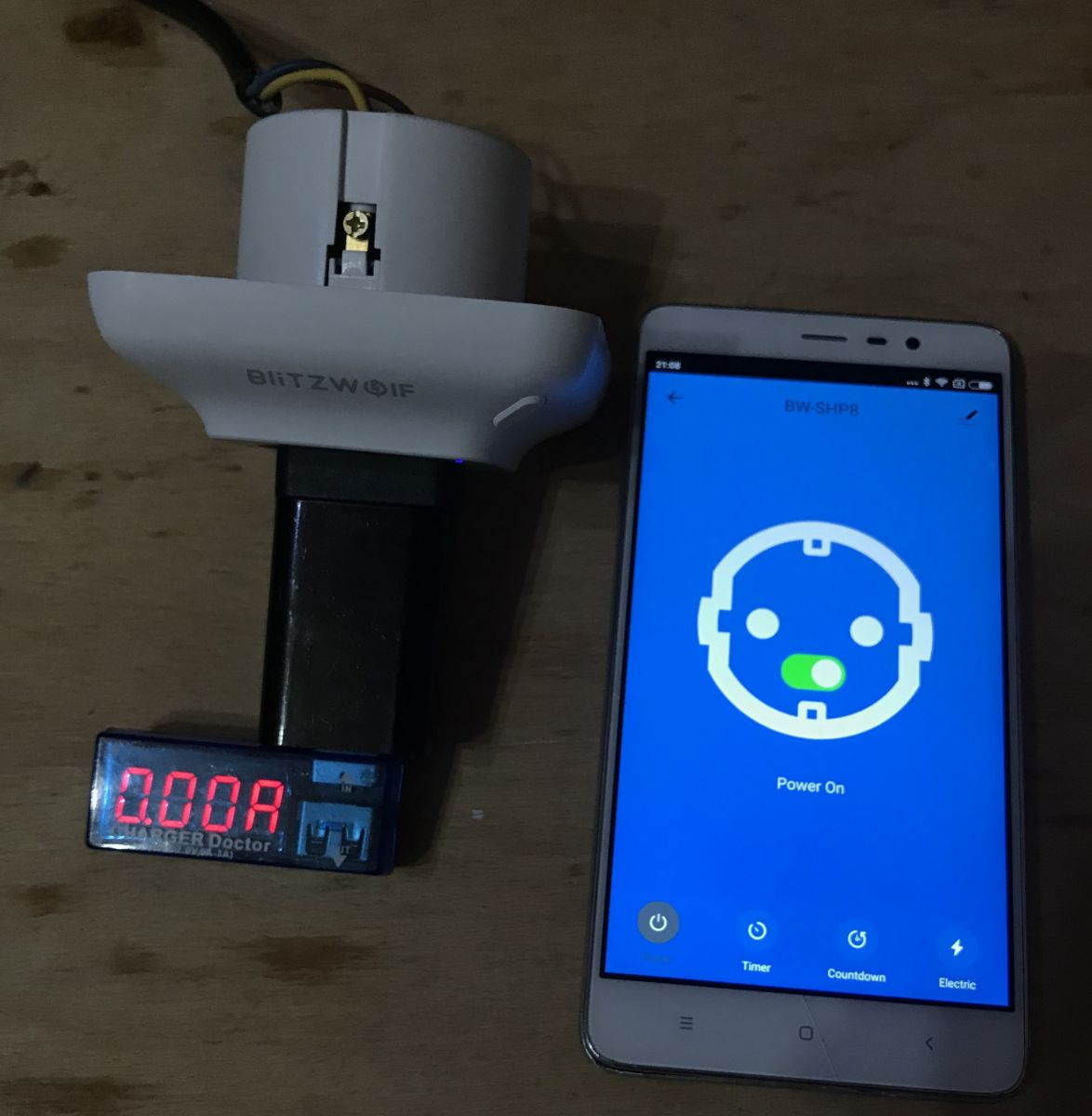
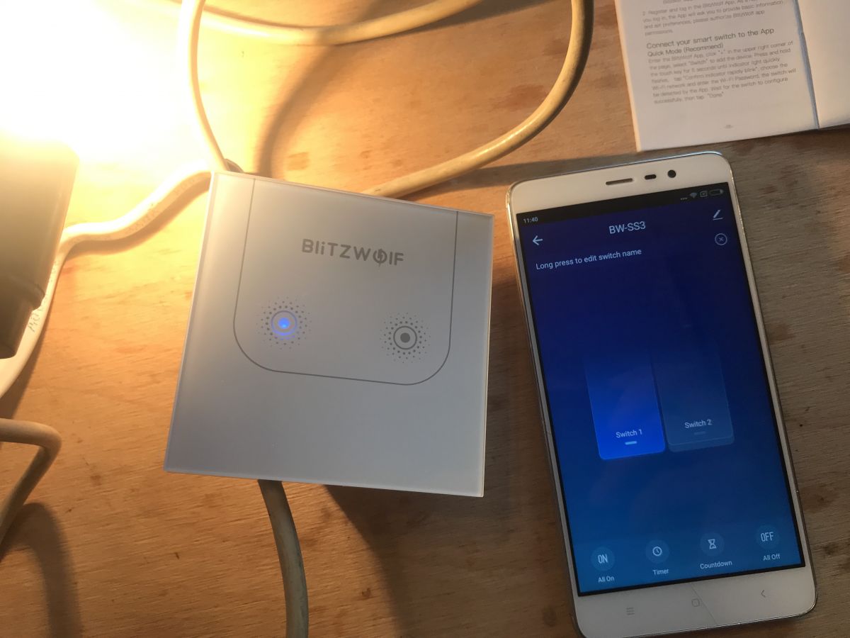
From this point I could control the switch from within the app. In its profile we have independent control over its two relays:

 .
.
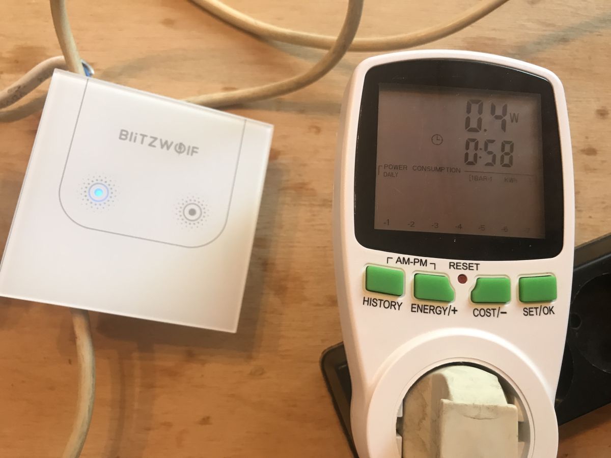
Finally, I measured the power consumption from the mains.
Standby mode, with no relays engaged - 0.4W:
 .
.
One relay on - 1.0W:
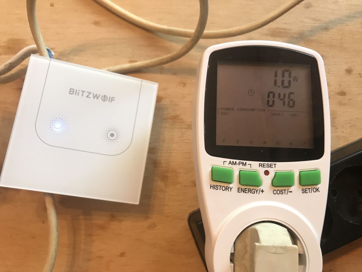
Both relays on - 1.7W:
 .
.
Interior of BW-SS3 switch .
The front cover of the switch pulls off very easily - just lever it up with a flathead screwdriver.
 .
.
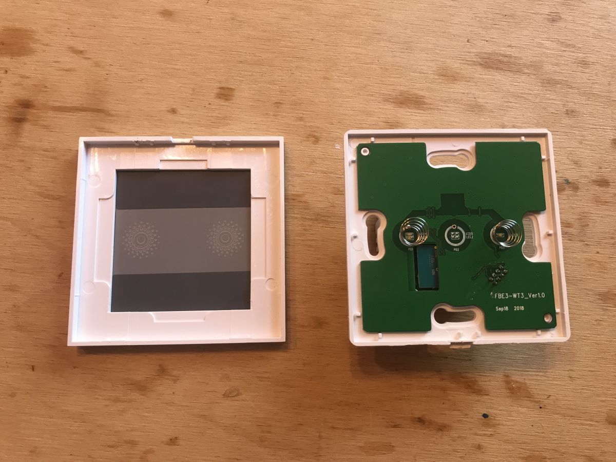
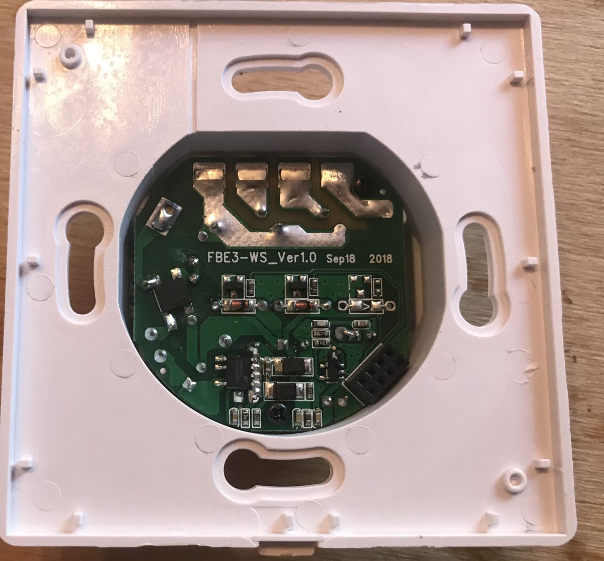
It is then immediately apparent that the manufacturer uses one type of board for all three types of switch (they just don't solder all the components and contacts):
 .
.
Above you can also see the four holes used to mount the switch in the box.
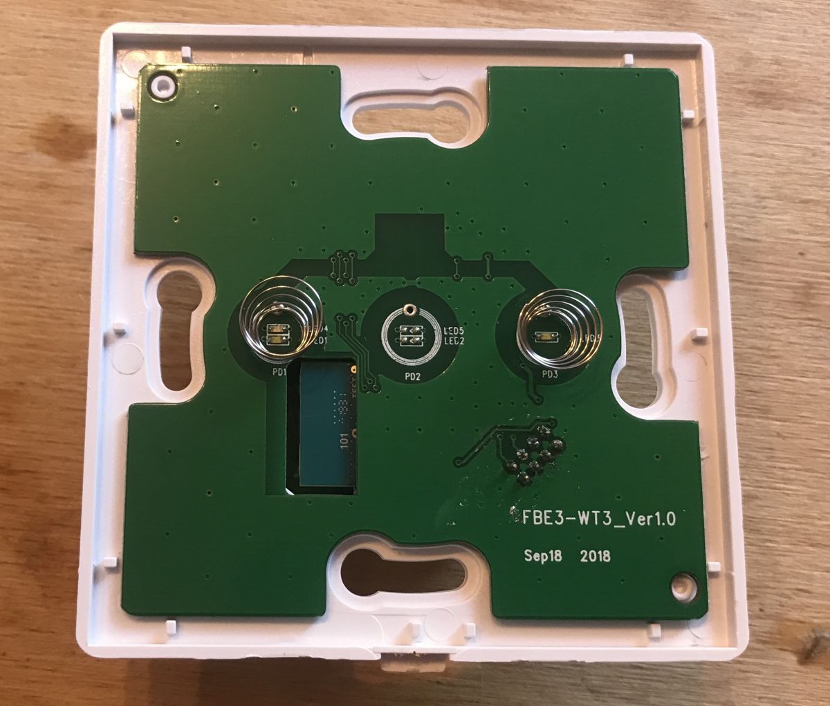
The board is signed FBE3-WT3-Ver1.0 Sep18 2018.
The board on the top is not attached to the rest of the socket in any way - it just holds onto the eight-pin 2.54mm connector (2 rows of 4 pins each):
 .
.
On the underside of the board you will immediately notice the WiFi module, which is soldered to it separately:

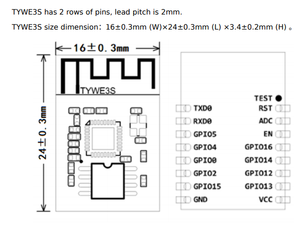
This module is the TYWE3S manufactured by Tuya:
 .
.
It is based on the ESP8266.
I have included its full catalogue note below:
.
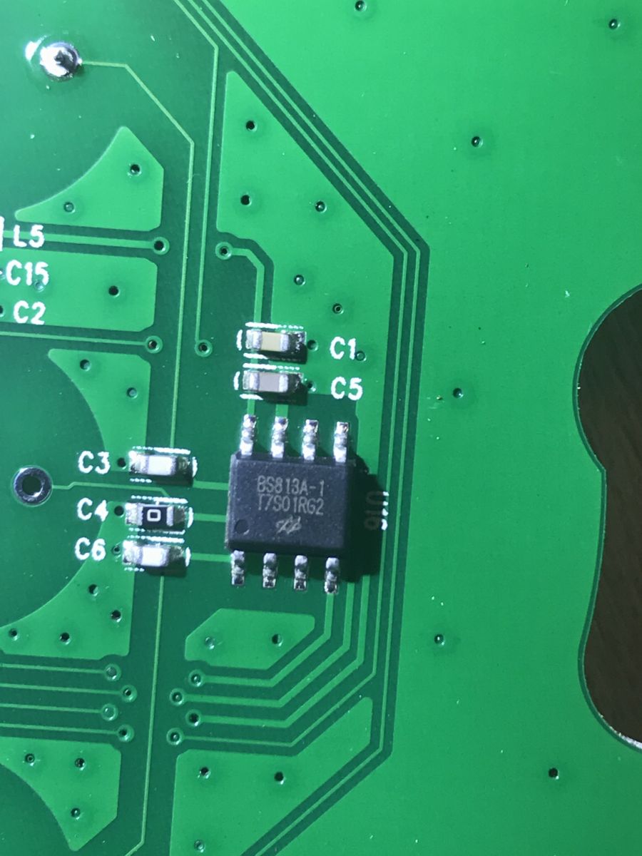
Right next to it you can see a small component with eight legs in an SOP housing:
 .
.
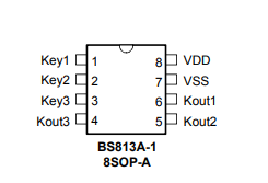
This is the BS813A-1 by Holtek - a touch button controller.
 .
.
I have included the BS813A catalogue note below:
.
Application:
.
There is nothing else of interest on the front board - you can look at the second board, the one with the two relays:
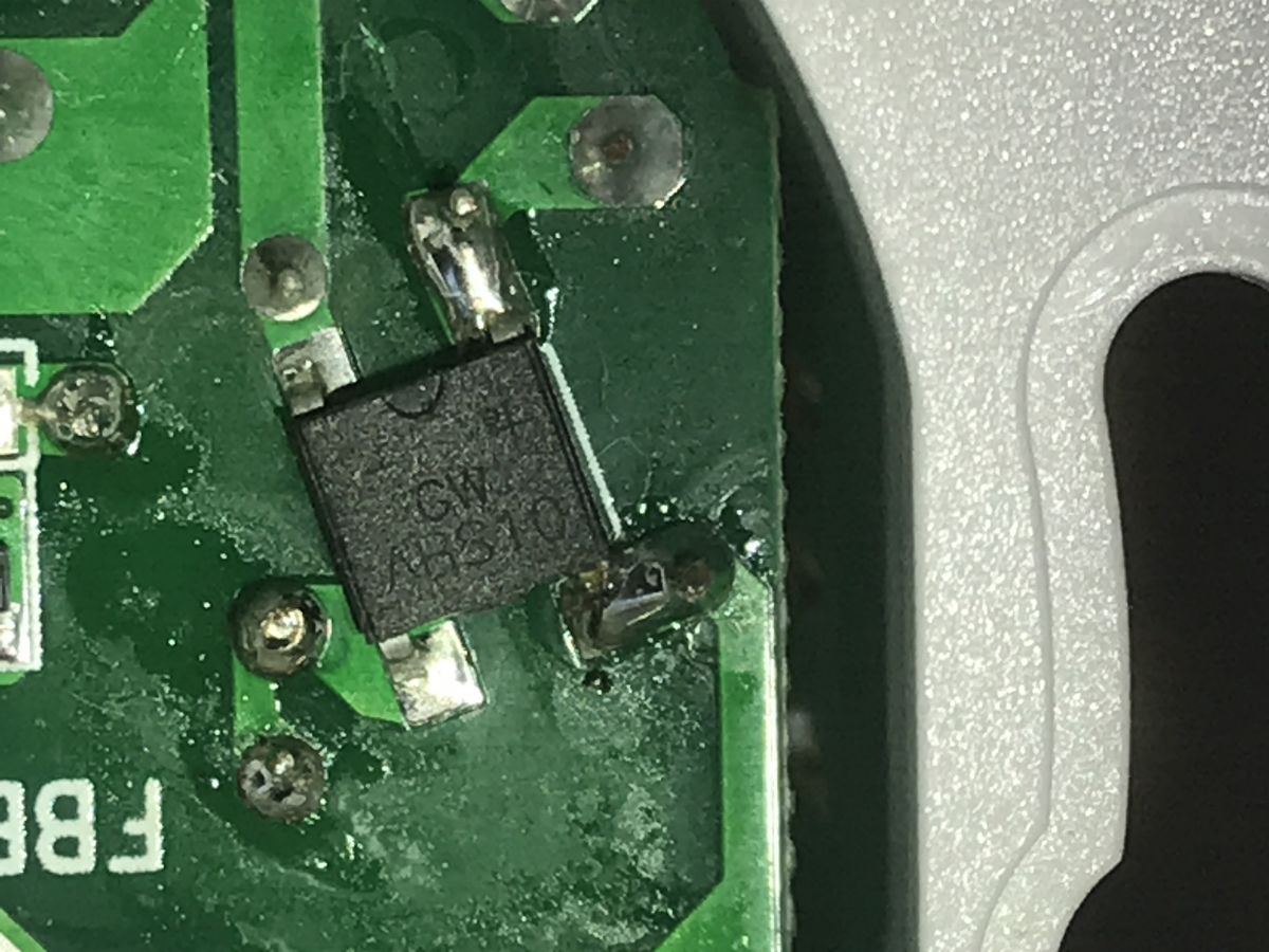
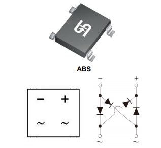
On it you can see the main circuit responsible for powering the switch. Directly connected to the mains is the ABS10 (Greatz bridge - four rectifier diodes in one housing):
 .
.
 .
.
ABS10 note:
.
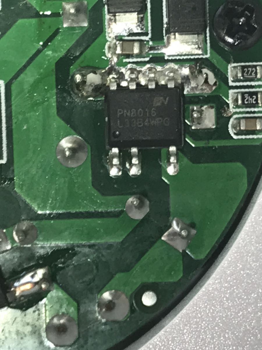
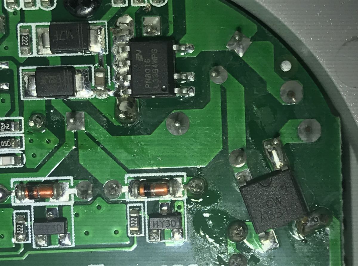
Just behind is the PN8016 manufactured by Chipown:
 .
.
 .
.
This is the so-called "Non-isolated Off-line PWM converters Width Modulator (PWM)", a converter circuit without galvanic isolation.
PN8016 application diagram:
 .
.
It is this circuit that converts the 230V mains voltage into a 3.3V supply for the WiFi module and relays.
I couldn't find the PN8016 datasheet note in .pdf format, the only link to it was dead, and I got the screenshots above from sales listings for this circuit from the web.
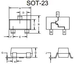
Next to it you can see two components in SOT-23 housings signed HY3D - that is the S8050MD NPN transistors:
 .
.
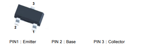 .
.
S8050MD catalogue note:
.
Each of these has a diode visible next to it - this is the transistor protection required by the relay, as it is these transistors that control the relays.
There is also space on the PCB for a third transistor and a third relay.
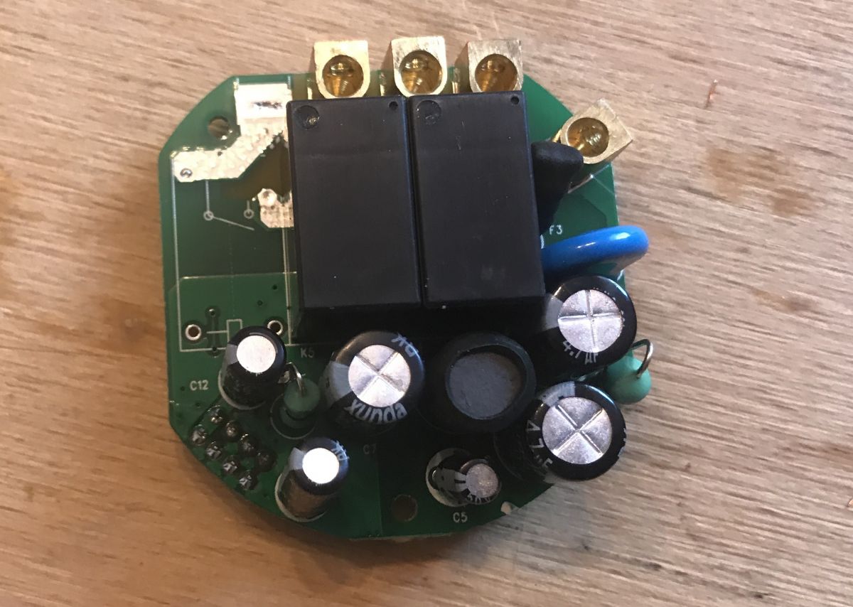
The relay board can be removed from the housing by removing two screws:
 .
.
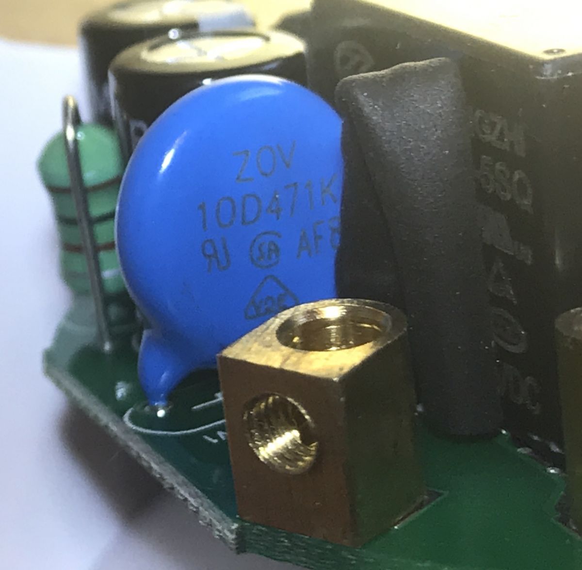
You can then see the 16V 47uF electrolytic capacitors (on the low voltage side), the 4.7uF 400V (on the mains voltage side, behind the Greatz bridge) and the large choke which is probably related to the PN8016. There is no transformer here - it is not needed for this type of inverter.
 .
.
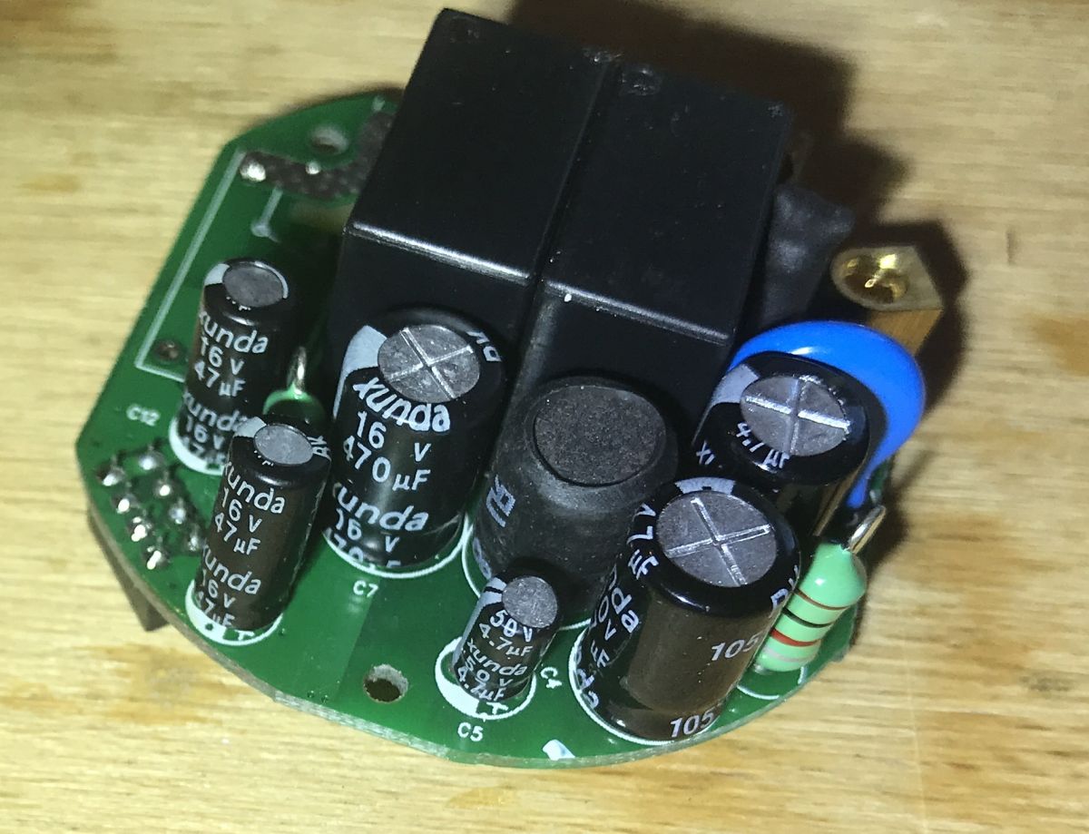
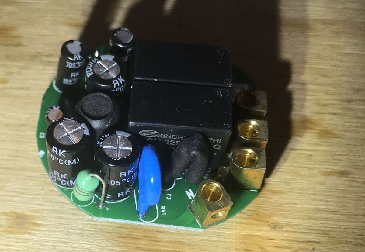
I could not read the relay markings, they are obscured by the components:
 .
.
 .
.
Pinout on 2x4 connector .
I added this paragraph a little later, at the user's request.
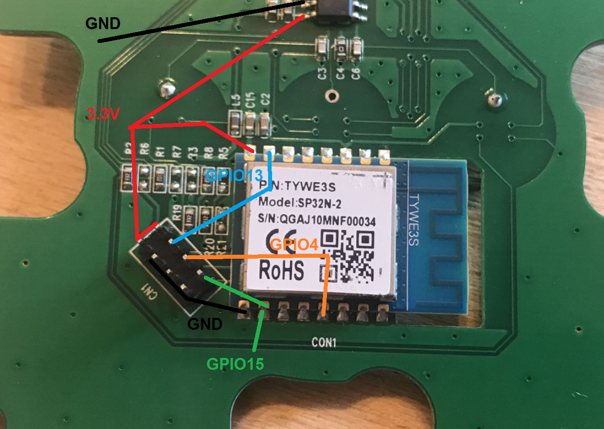
Here's a breakdown of the pins that go on the 2x4 connector, that is, they connect the power supply/relay board to the board from TYWE3S:
 .
.
As you can see only three pins are brought out to control the relays, the rest are ground and power.
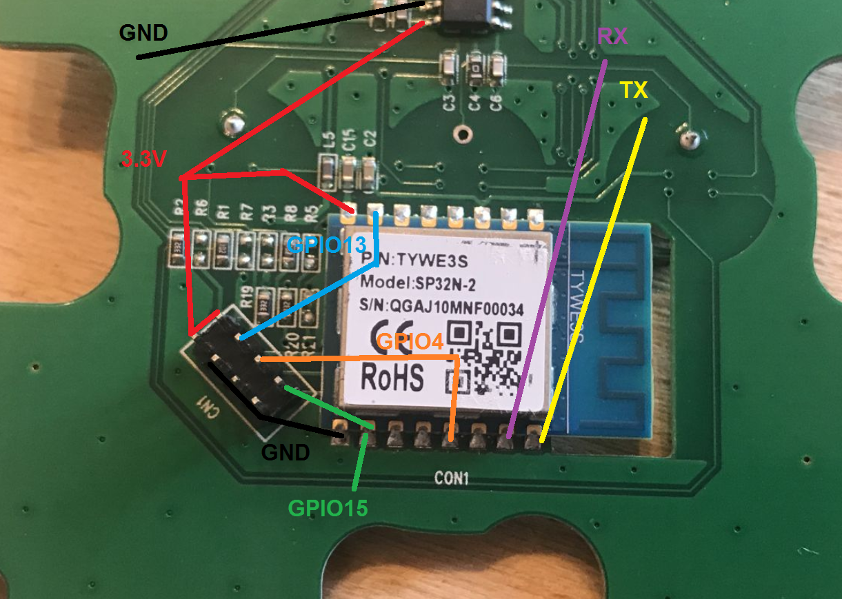
So unfortunately this connector is of no use to us when trying to upload our own firmware. We will rather be interested in these pins (TX and RX):
 .
.
But I will write about the option of uploading custom firmware to this type of device another time.
I also recommend that you take a look at the pinout from the Tasmota website:
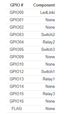 .
.
Summary .
The BW-SS3 WiFi light switch proved to be easy to set up and use. I installed it for a trial at my home (it went into the box without a problem) and will find out over time if any problems come to the surface though, and if not, I may consider replacing my other light switches with WiFi ones at some point.
As for the interior, the BW-SS3 is built similarly to the the previously described BW-SHP8 . BW-SS3 is realised on TYWE3S and BW-SHP8 is realised on TYWE2S. In addition, the power supply issue has been clarified - looking inside the BW-SHP8 I did not see a transformer, only a large choke, but at the same time I did not have access to the inverter controller chip, and in the case of the BW-SS3 it is clear that the power supply is realised on a PN8016 chip.
The BW-SS3 is also supported through the Tasmota open source alternative firmware project, perhaps I will describe the process of uploading it soon.

p.kaczmarek2 wrote 14683 posts with
rating 12711 , helped 656 times.
Been with us since 2014 year.
Comments
Are there all the signals needed to program the ESP on this 2x4 connector? There is probably power and ground. You still need Rx, Tx and GPIO0. If you can give a breakdown of this connector, as probably... [Read more]
The problem with these types of devices is that they require a dedicated app to work. In a year, year and a half, the manufacturer will have gone out of business, the app will not be updated and the switches... [Read more]
This is one of the reasons why I program them myself. It's my programme, nothing goes out to some 'cloud'. I just have full control. In a previous post I asked the Author a question about the leads needed... [Read more]
. This is a very good question - it's a wonder I didn't think to specify it. Had to wait a bit for an answer as the switch was already in the wall (I'm testing it, for now, with a Blitzwolf) so I had... [Read more]
Thank you very much for the connector layout - it's a pity there is such a waste of pins. So you can program by adding wires. This is where I see a potential problem - RX is GPIO3, and it is used as an... [Read more]