In this topic, I will first show you the inside of the printer in detail HP Deskjet D1360 , and then I will show you how to use its parts with Arduino. I will specify the pinout of the encoder from the inside, write the code to determine the position of the carriage using the encoder, and of course drive its DC motor with the help of an additional H-bridge module. The end result of the work will be my own Arduino sketch to position the carriage of this printer at the position we want.
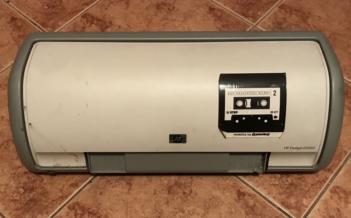
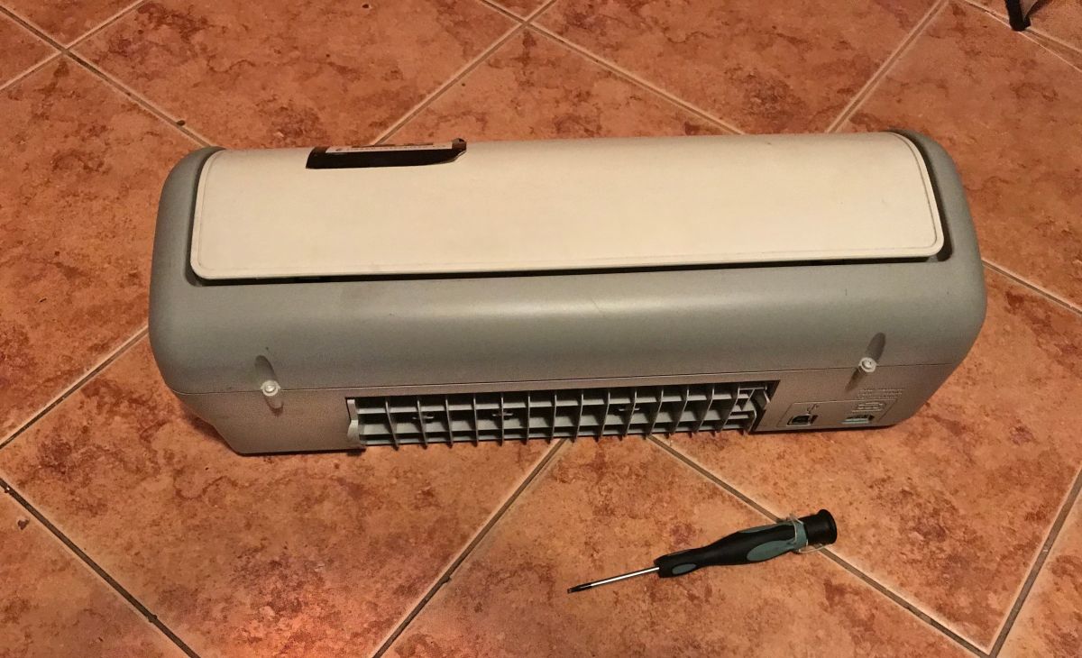
HP Deskjet D1360 printer teardown I received this printer in bulk, without a power supply - I just saved it from electro-waste.
Printer from below:
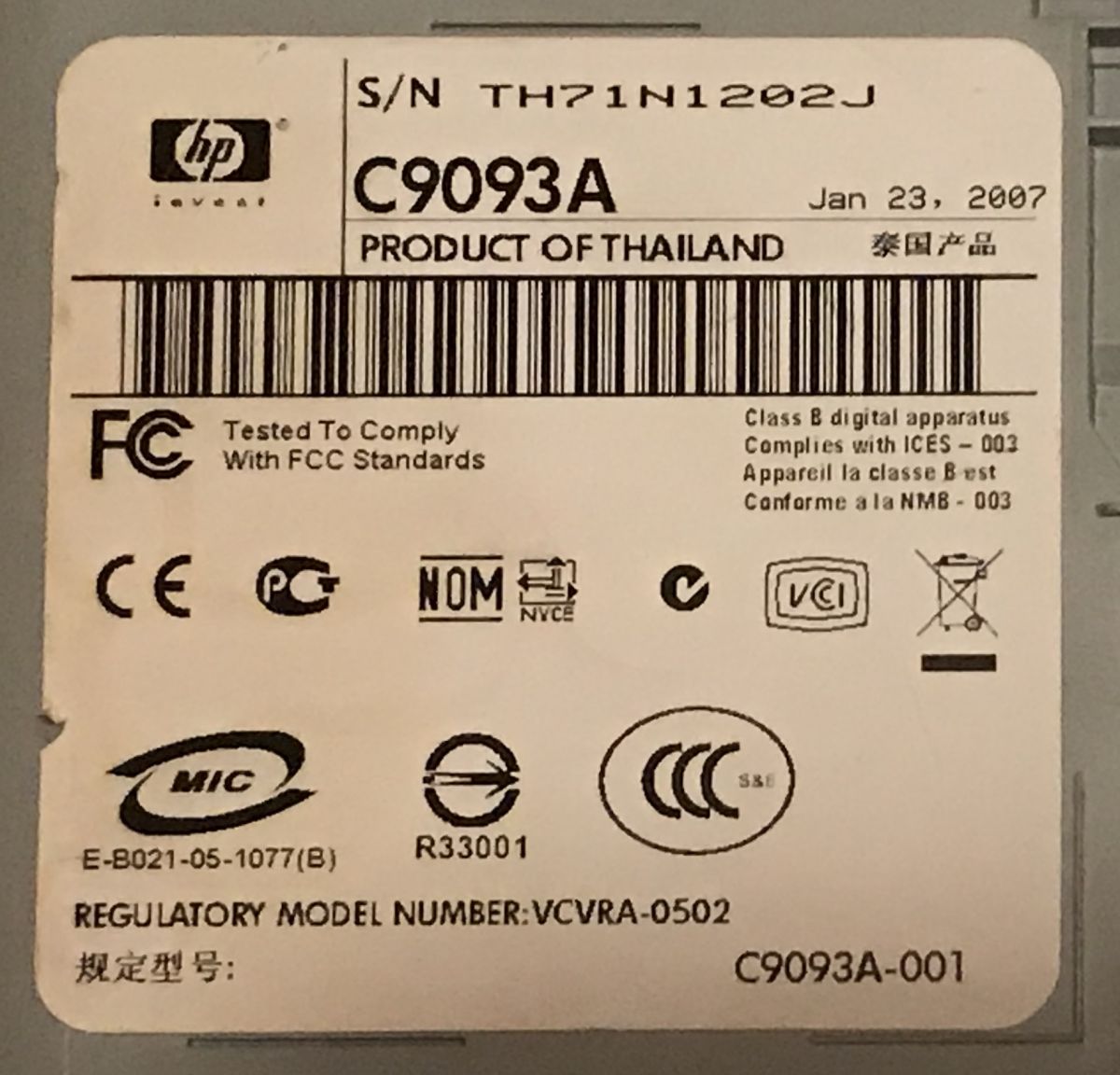
Nameplate:
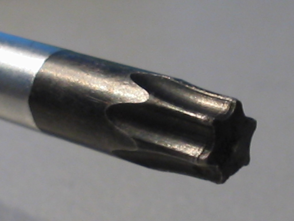
To get inside, we will need a torx (so-called hex/star) screwdriver, such as:
(Torx screwdriver tip; source: Wikipedia) I also prepared this:
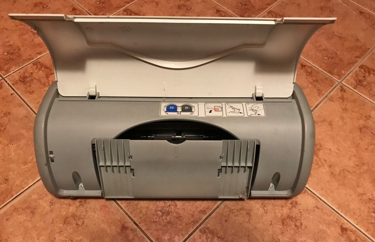
Often, the printer cover must be opened to expose the screws:
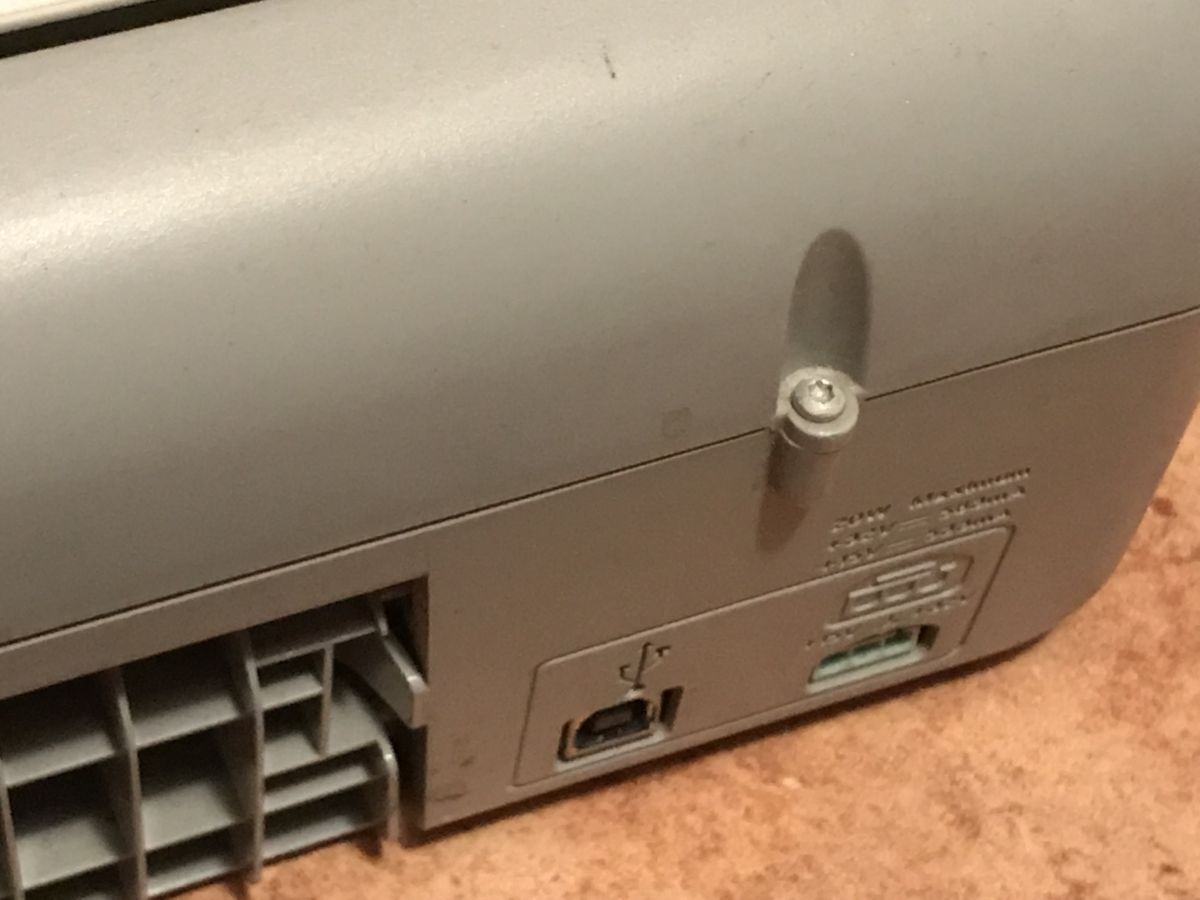
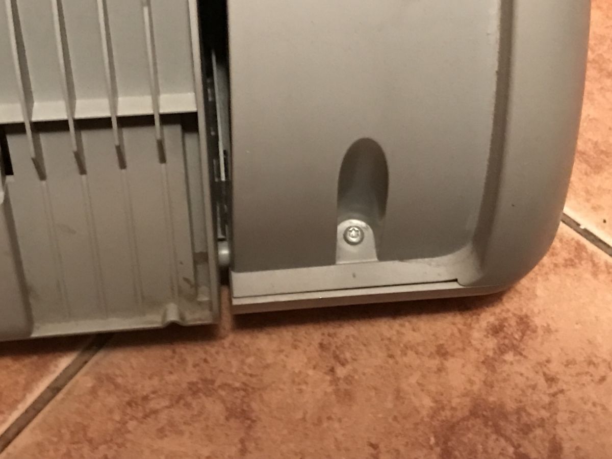
The screws are on both sides of the case, front and back:
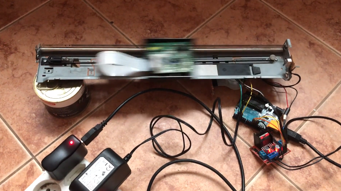
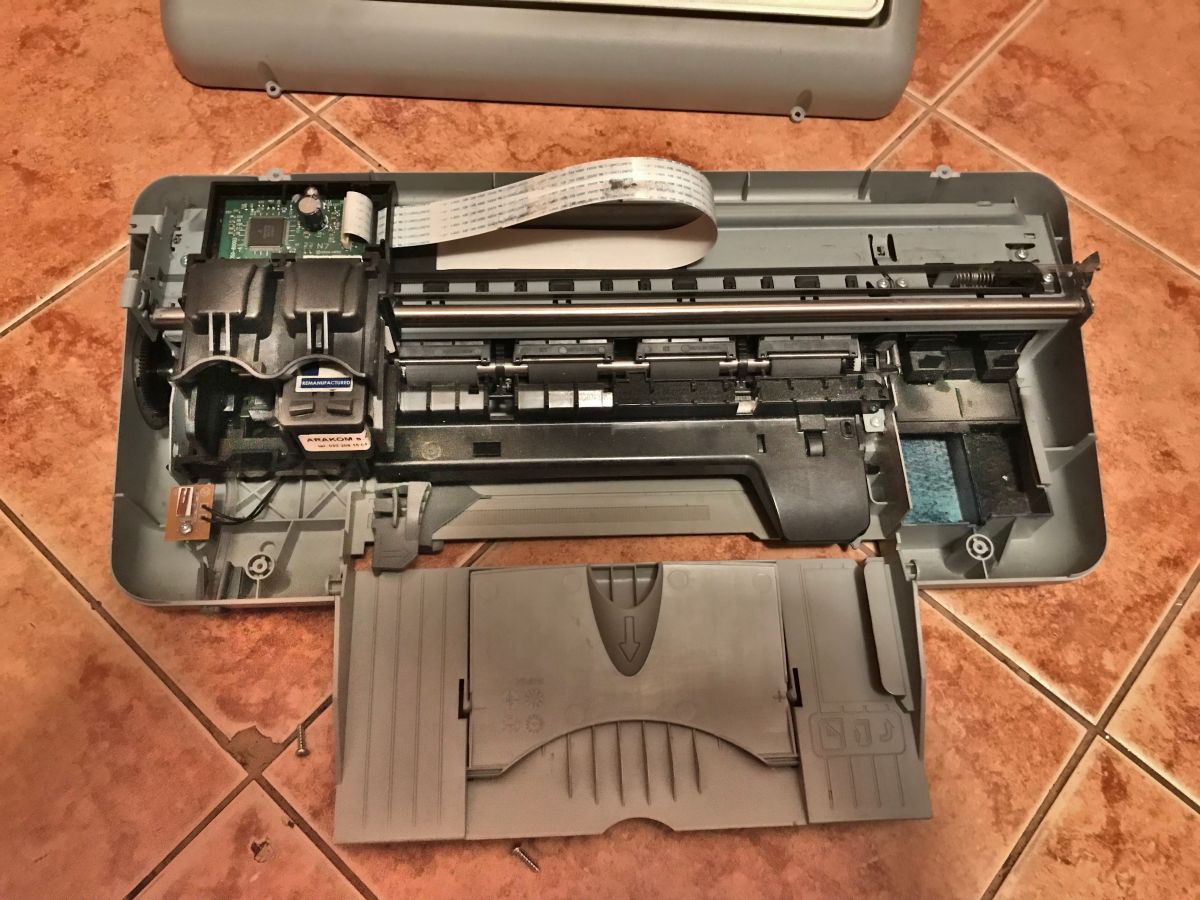
After unscrewing the top cover, you can already look inside the printer:
Inside, we can see the moving mechanism of the carriage with two ink containers (which move along with it).
Interestingly, this mechanism is based on a regular DC motor, not a stepper motor. At this point, you can't see it yet, but you can easily see it after dismantling the whole thing - there are only two wires going to the motor.
The motor itself and the mechanism of the carriage are also screwed with torx screws:
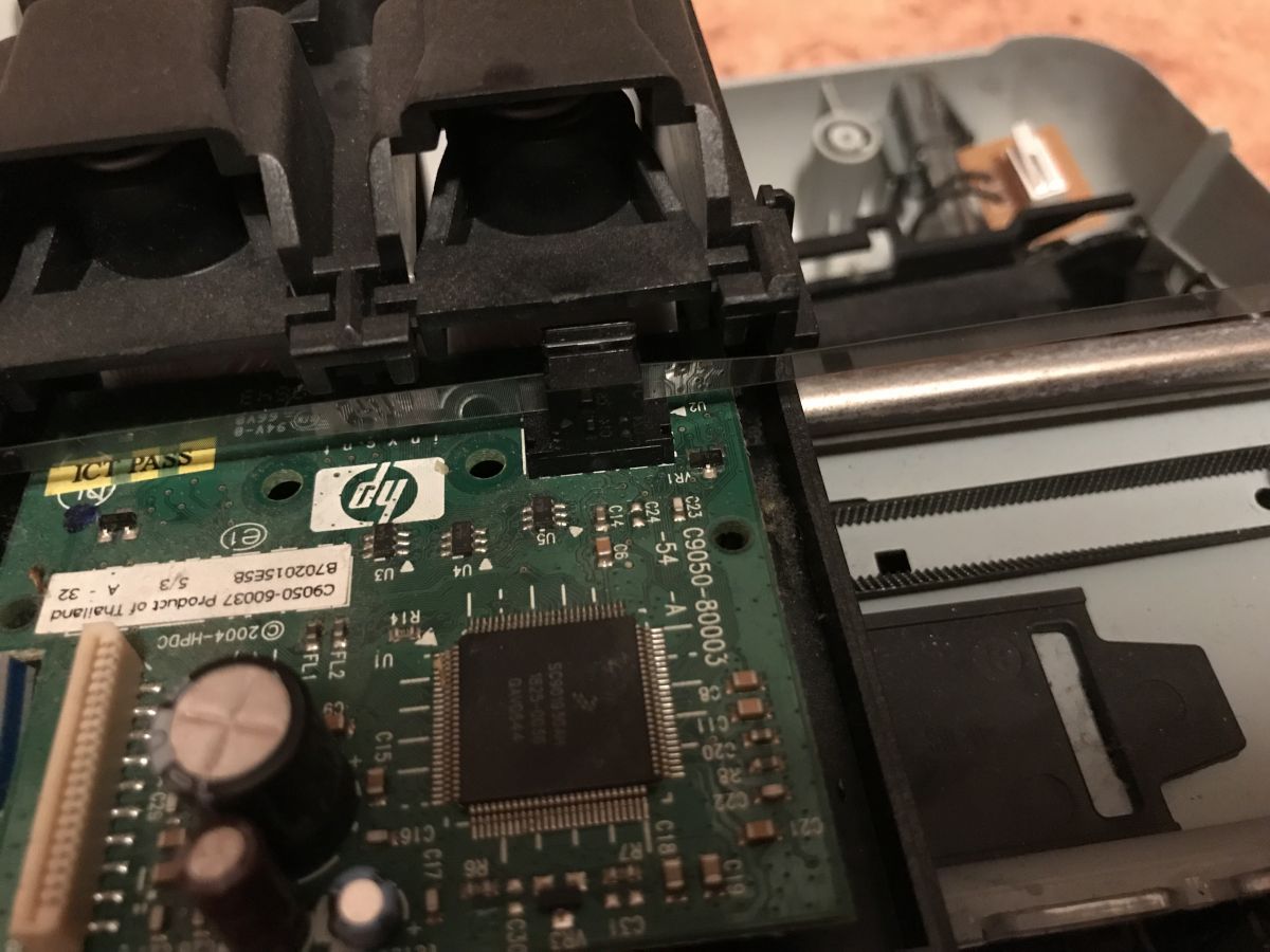
The printer determines the position of the carriage based on the encoder (here this encoder is double - it has one diode and two phototransistors, but more on that later) which counts color jumps on the foil strip:
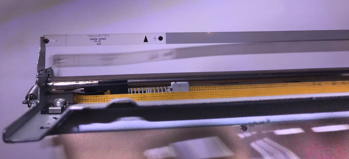
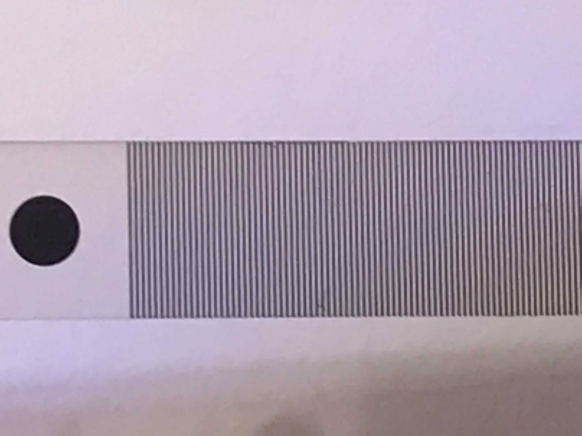
Now I will show these stripes up close. I had to use better lighting and background (white sheet of paper) to take this photo.
Here's a foil strip (so-called 'encoder strip') in a good quality photo:
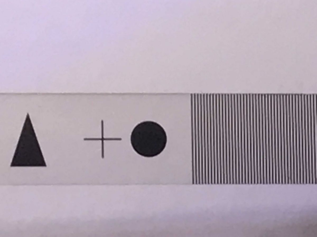
Here with zoom:
And with a bit more magnification:
The stripes are clearly visible.
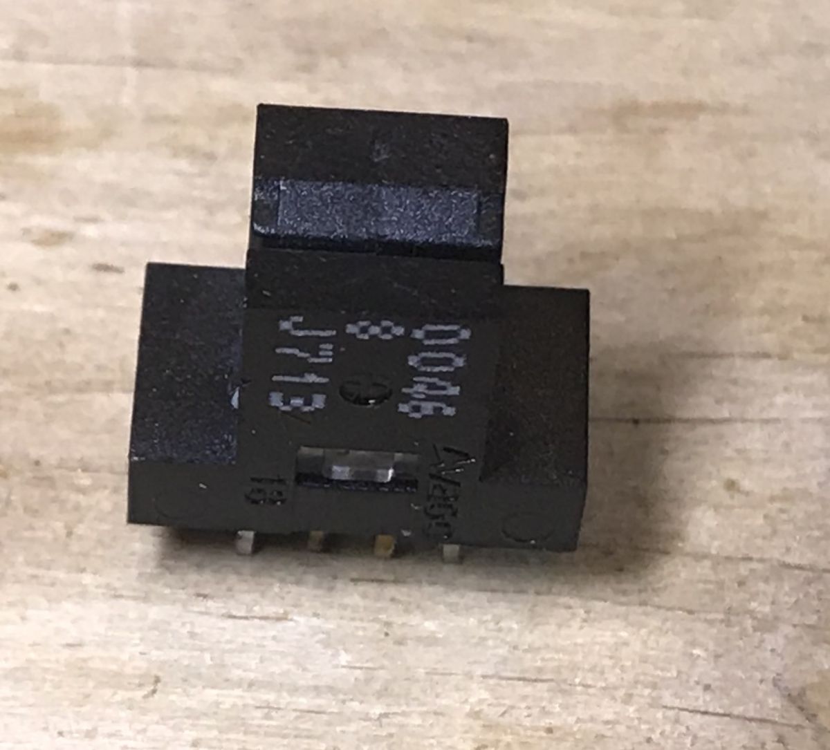
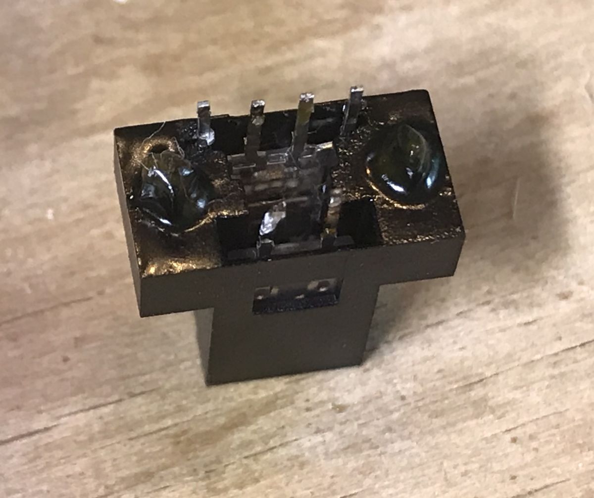
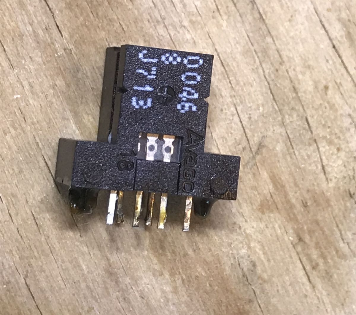
The encoder itself after desoldering looks like this:
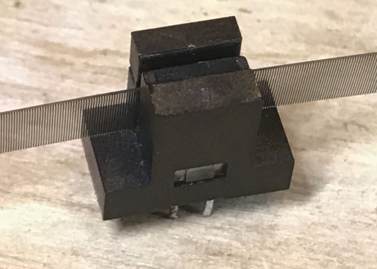
Strap slot:
With strap:
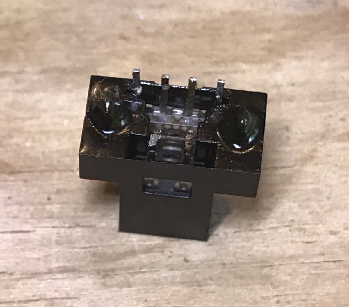
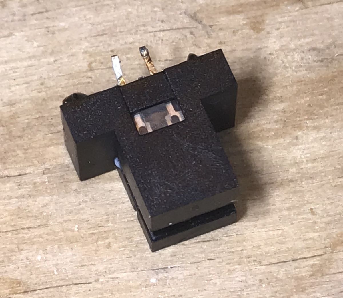
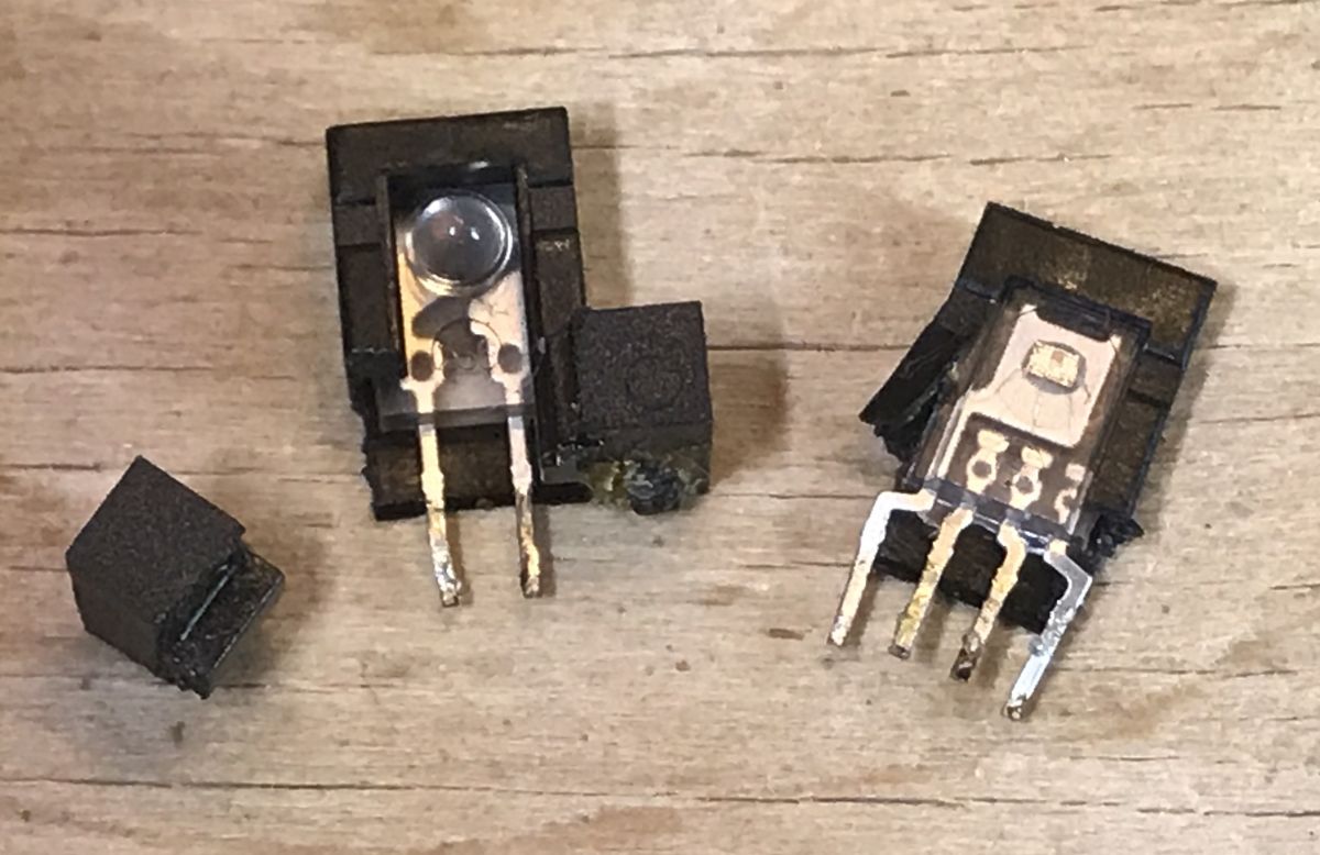
Encoder center; bisecting it like this is of course can be destructive, I did it to show its insides here:
The diode and the receiver are clearly visible.
(But this is not the encoder from the printer being dismantled here, but from another one; I did not desolder it from this printer from the topic)
I will come back to the topic of the encoder and its belt.
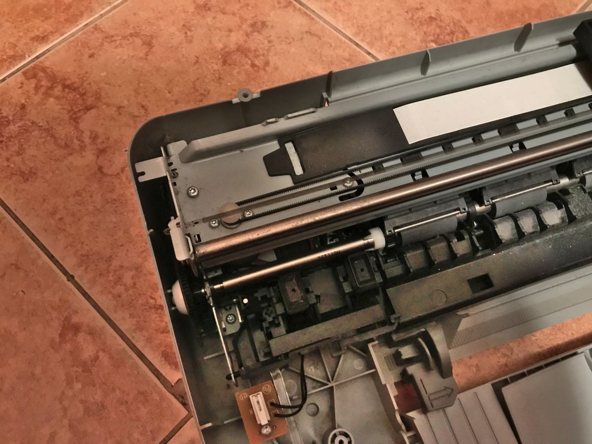
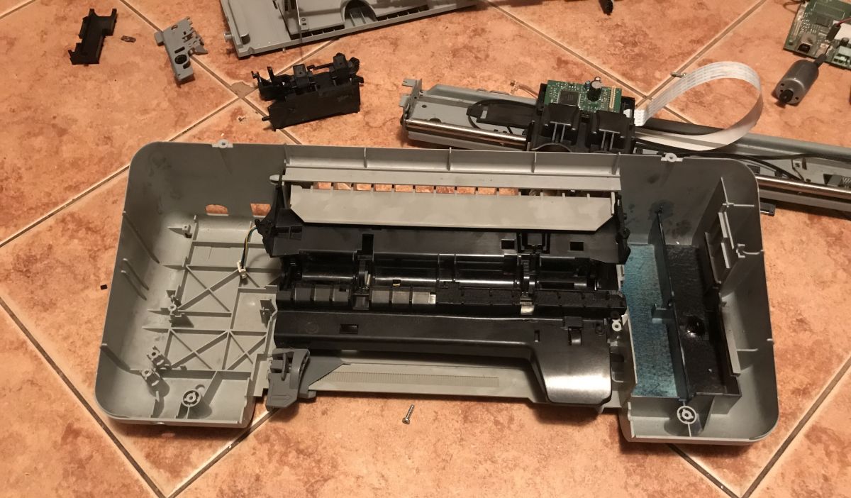
Continuing the teardown of the printer: after removing the rail with the carriage, we can get to the motherboard and the second DC motor, here responsible for paper feeding:
In this way, we are practically left with the plastic base of the printer:
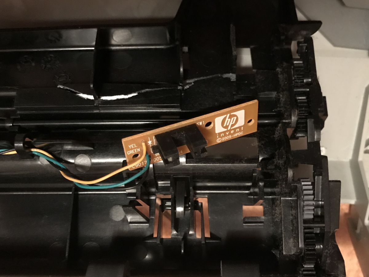
However, there is another valuable element hidden in the photo above. It is located in the plastic paper tray:
Often it is not even screwed on, but held on by hooks.
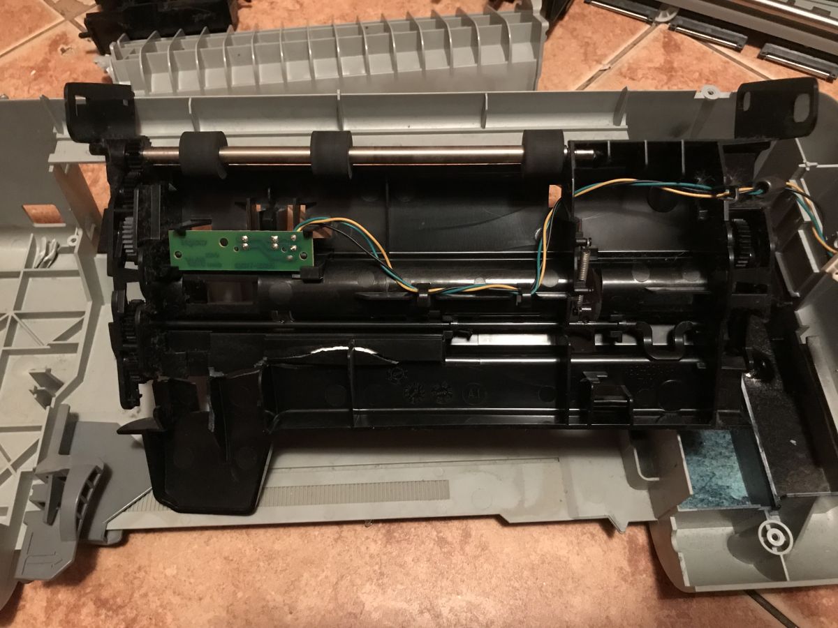
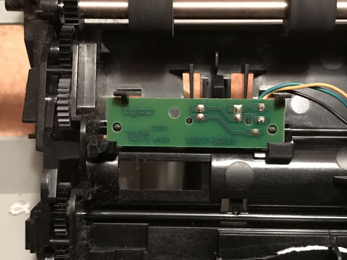
This is a board with another encoder, here even with a diode symbol (so we know what the pinout is):
And that will be all about the teardown. Below is a summary of the demolition.
Obtained items I kept only what I found useful from the printer. The plastic housing and unnecessary metal elements were immediately disposed of.
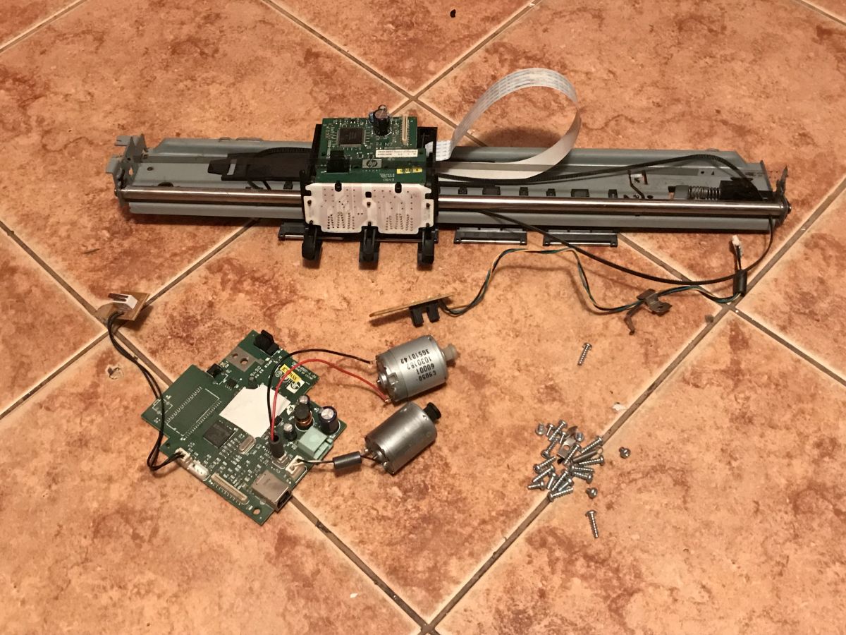
I left only these parts:
In the photo you can see:
- carriage guide with a moving carriage (on the carriage there is a board with an integrated circuit and a double encoder; on the guide there is a striped black stripe for the encoder)
- two DC motors (one from the ejected paper feeder mechanism, the other from the carriage, here separately)
- a button on a separate board on two wires
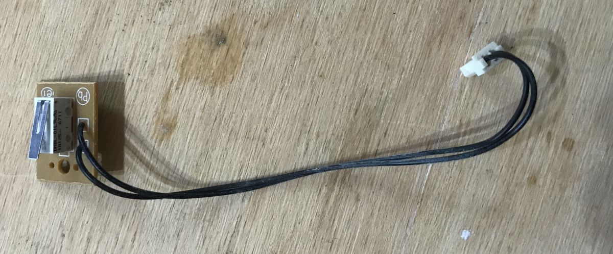
- single loose encoder on a separate board
- motherboard from a printer with a USB connector and another encoder
- screws
In the above set, there is not a single stepper motor (as I have already found them in the systems from the scanner) and there is no power supply, because this printer had an external power supply that probably did not come from me.
Below I will try to make some of the parts shown here and demonstrate that they can be used for hobby projects.
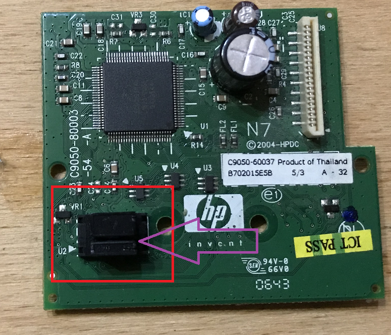
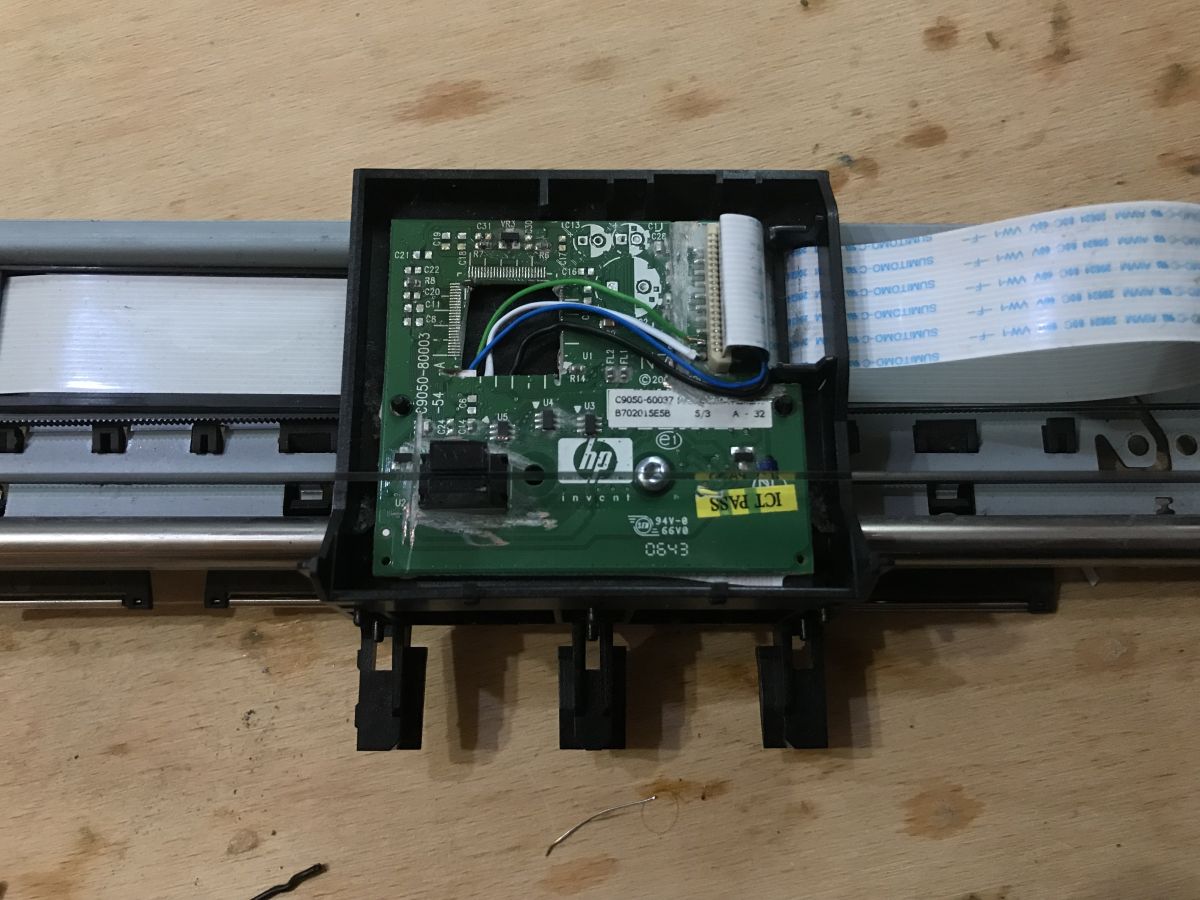
Encoder pinout from carriage The first thing that interested me was the encoder that allows us to determine the current position of the carriage. The encoder has a slot for the previously mentioned strip:
This encoder has 6 leads, two on one side and four on the other:
This encoder contains one diode and two sensors. I have sketched its diagram below:
Between the diode and the two sensors, the previously shown bar moves - while moving, it covers the sensors (sometimes one, sometimes the other, sometimes both), which allows us to determine its movement and thus the position of the carriage.
The diode from the encoder obviously requires a resistor - it's possible that it is somewhere nearby on the PCB. If we run the encoder ourselves, we also have to remember to put this resistor there.
The encoder pins themselves are not marked and I was unable to find its documentation on the Internet, although I found information that they are not standardized and may vary depending on the printer model.
That's why I think it's worth knowing how to determine which pin is which.
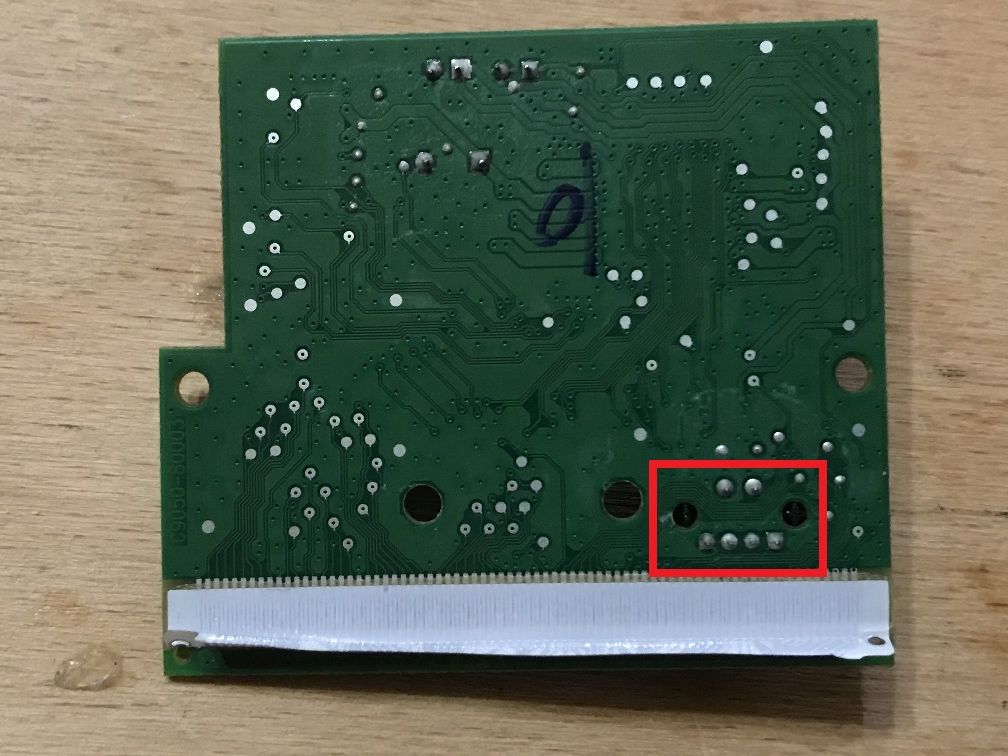
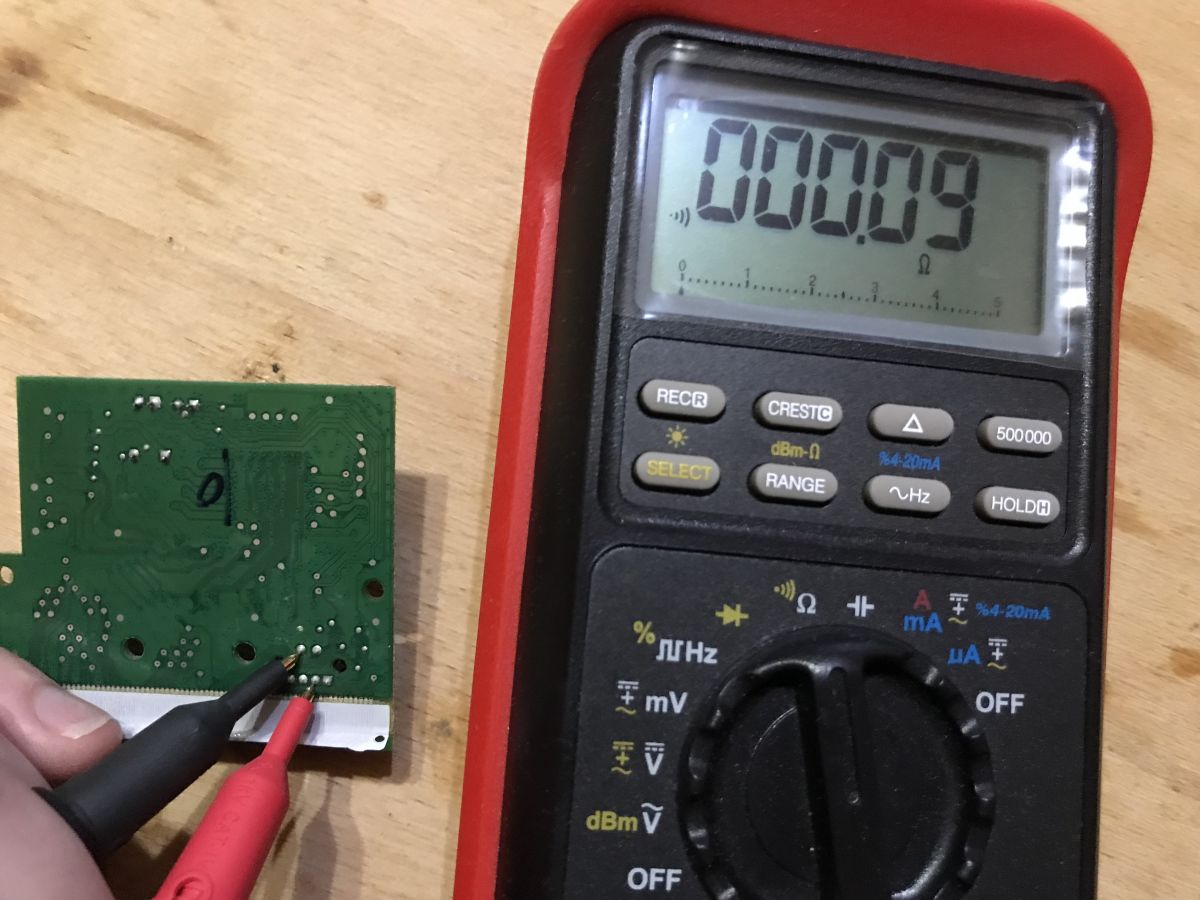
You can start with the simplest - mass: This pin, of course, will be connected to the mass of the entire system / mass screed on the board. In the picture above, I show that there is a direct connection between the selected encoder pin and the test ground pin on the PCB.
Then it is worth recognizing VDD - power supply - in my case it was on two pins: The fact that it is VDD can be guessed by elimination. If it is not mass, what else can be on two pins in such an encoder? Just the power supply - VDD. It is connected both to the diode from the encoder and to the phototransistors from it. VDD is also often connected to the + electrolytic capacitor.
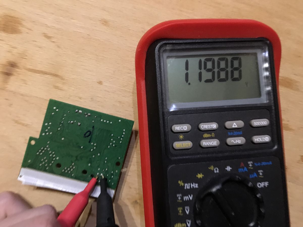
Next, I made sure of the diode leads. They are on one side of the encoder where there are only two pins. I used a diode test in my multimeter for this - it shows the voltage drop. Of course, the diode conducts only in one direction, the other side of this reading will not be.
At this point, it is possible to determine which pins (the other two) are the signal outputs of the sensors using the elimination method.
This is how I recognized the encoder pins.
Finally, it should be noted that encoders really have different pins and sometimes, for example, they have ground on two pins, and sometimes power on two pins...
It should also be remembered that the encoder at its diode does not have a resistor - we have to put it there ourselves.
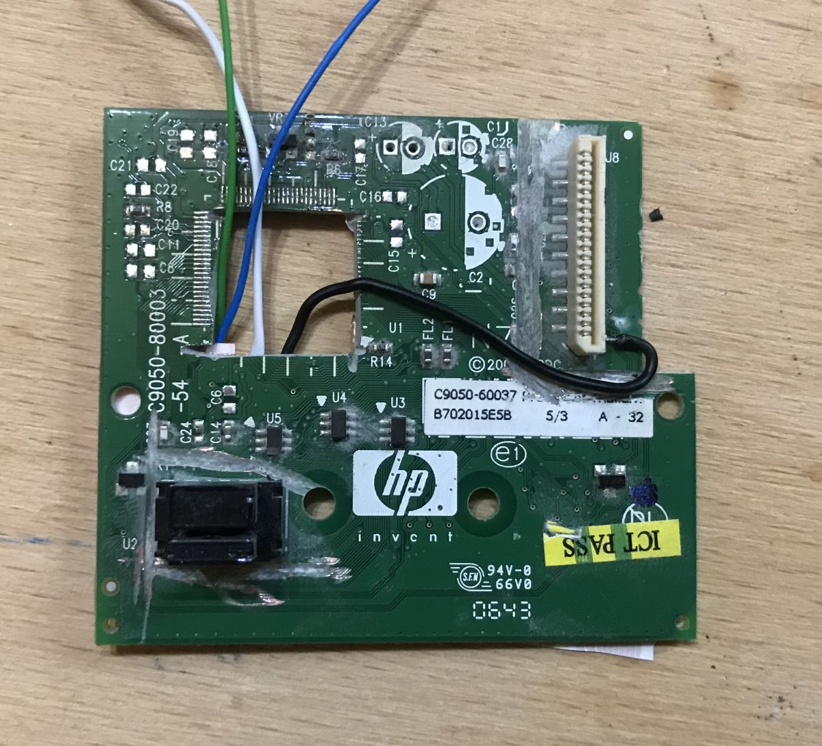
Connecting to the encoder and carriage Now for something not very revealing, but necessary - a way to connect to the encoder on the ambulance.
You can just give your own wires and maybe it's the easiest way, but I decided to use the existing ribbon.
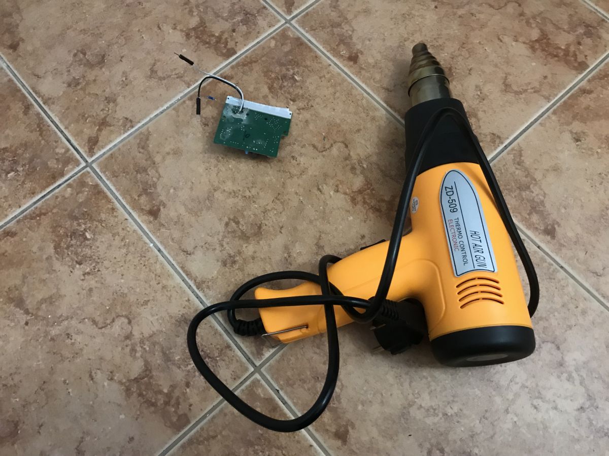
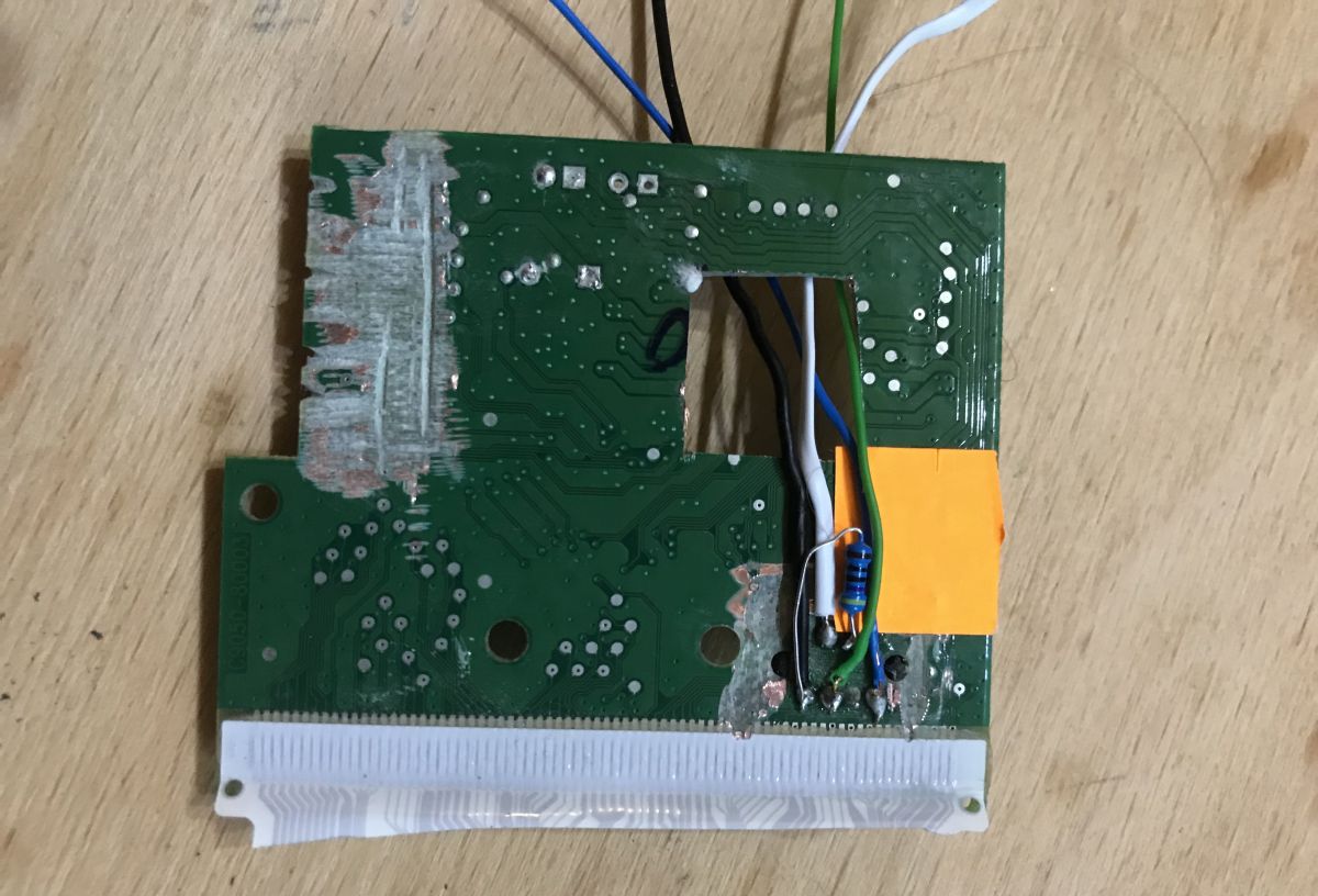
For this purpose, I removed the redundant chip from the board with a hot air gun and removed all connections of the chip with the ribbon (with its connector) using a small grinder:
I emphasize - when making a connection using this method, ALL SHORT CIRCUITS and UNNECESSARY ELEMENTS from the pins from the ribbon and from the encoder legs must be removed. Otherwise, you can waste a lot of time checking why something doesn't work because it will, for example, short-circuit the signal unnecessarily, a forgotten SMD resistor or a via. Then I made connections directly from the encoder pins to the ribbon connector pins. For this I put a resistor there:
Finished carriage board:
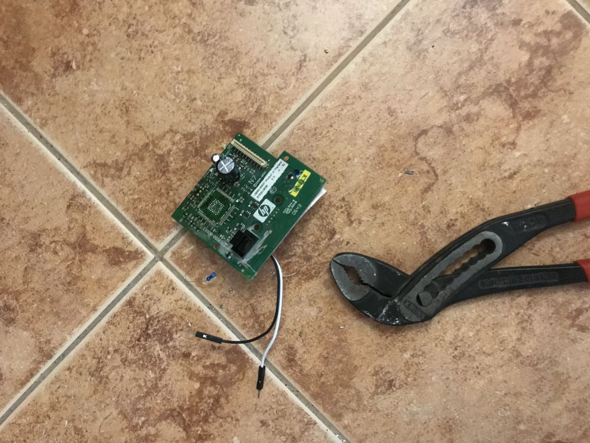
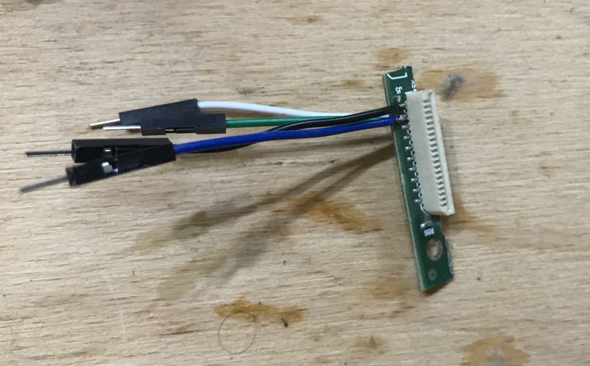
Now you need to repeat the same procedure for the connector on the other side. I cut the ribbon connector from the PCB and checked it with a multimeter for short circuits, and I removed the ones that were.
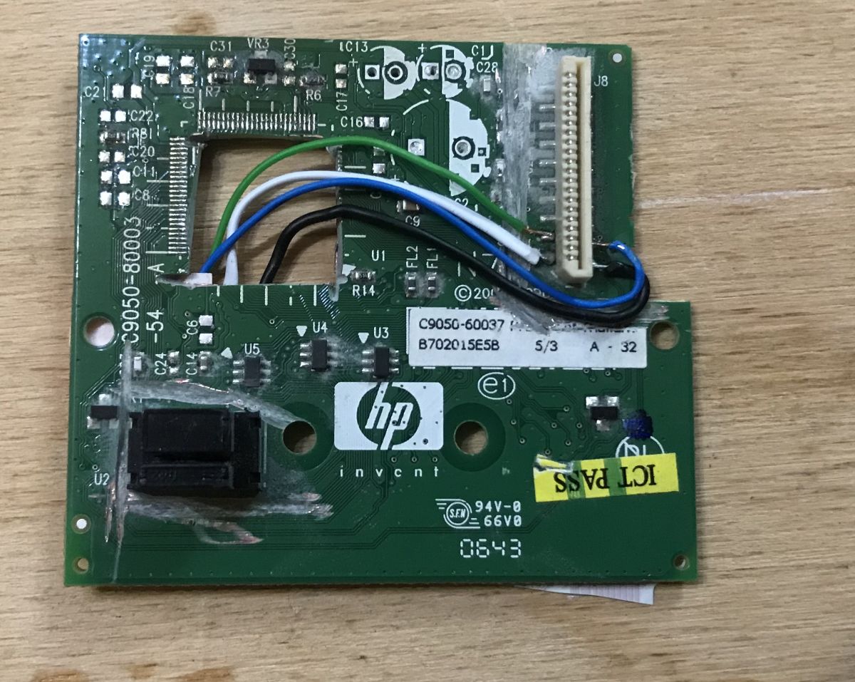
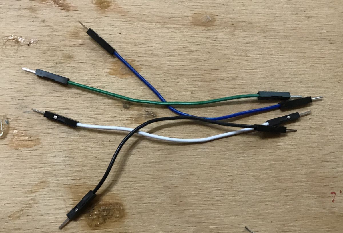
I soldered the wires to this connector that match the Arduino:
I kept the colors of the connections in accordance with what I had with the encoder:
This is how all the necessary connections for the test with Arduino were created, which I will present in the next paragraph.
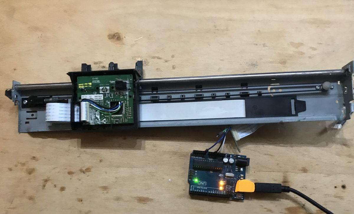
Encoder test - ADC First, I tested the encoder using ADC. I first powered the encoder with 5V, but it soon turned out that 3.3V from Arduino is also enough and I recommend you to use this voltage at the beginning.
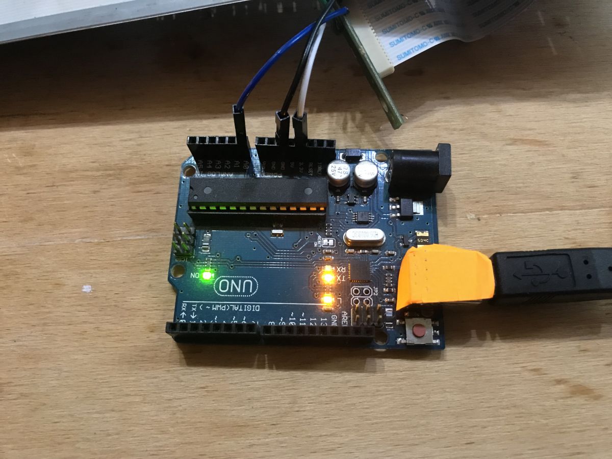
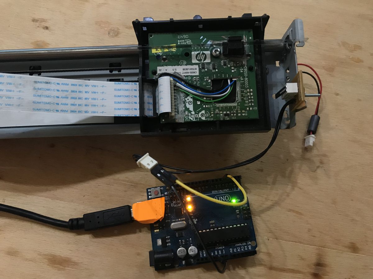
The connection to the Arduino is shown in the picture:
Sketch used:
Code: C / C++
Log in, to see the code
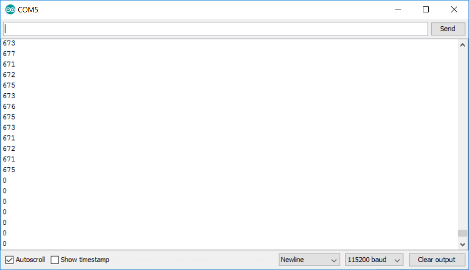
Result (during head movement):
It seems that everything is ok - the value from the ADC is the same because I powered the encoder with 3.3V from the Arduino board and not with 5V.
1024*(3.3/5)=675, which is about what we see on the UART.
Then I changed the program so that it does not use ADC.
Encoder test - digitalRead The code below does essentially the same thing as the previous example, just uses digitalRead instead of the completely redundant analogRead. It is worth noting that I configure the encoder pin here in the input mode with a pullup resistor (for power supply), i.e. INPUT_PULLUP, and not, for example,. INPUT only.
Code: C / C++
Log in, to see the code
Result (while moving the head):
I checked both encoder outputs with this code and both gave the correct reading.
Encoder test - reading from both sensors Then I modified the code to read values from both encoder sensors at the same time. This will allow us to observe how they change relative to each other as the carriage moves.
Code: C / C++
Log in, to see the code
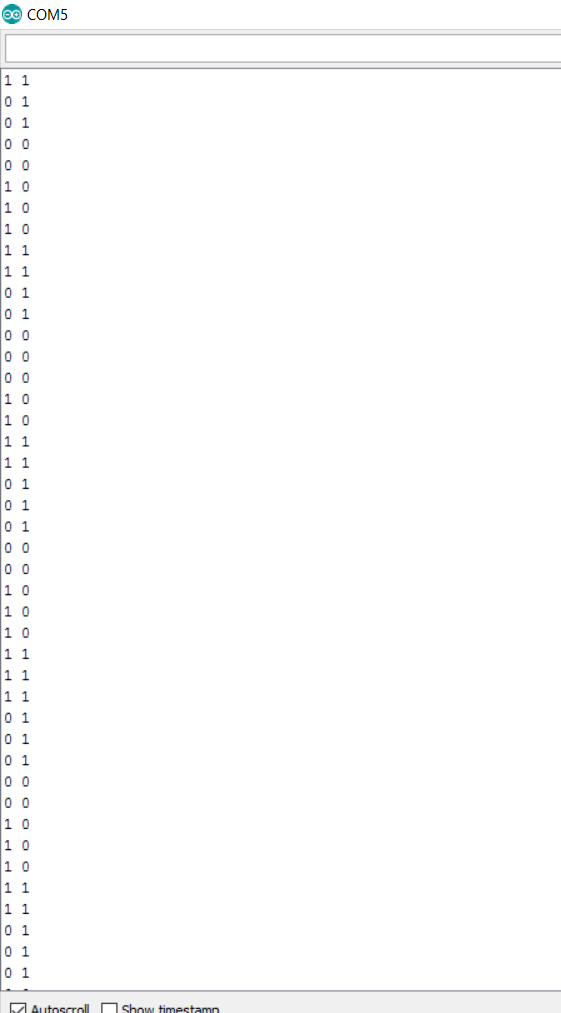
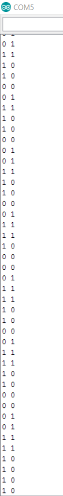
Below are the results of running the code.
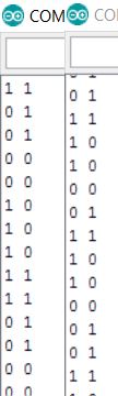
Movement to engine side: Motor side movement: Comparison in one picture:
You can see here that thanks to the use of two sensors of this encoder at once, it is also possible to determine the direction in which the carriage moves. I will definitely use it a bit further.
(of course, to have meaningful readings, the Arduino must keep up with the encoder sampling and must not lose the stripes)
End/stop position detection - 'endstop' Another thing that will be useful to do is to detect the initial (or, if you prefer - final) position of the carriage - that is, end stop. This is something almost unavoidable - even 3D printers (including my Ender 3 Pro) have a similar mechanism.
I will implement it here based on another element removed earlier from the printer:
This element simply closes the contacts when pressed.
Its designation is DMBL-01L 1A125 and you can find some information about it on the web. Interestingly, it is also used in computer mice:
But I don't think we need any more information about it - it's handled like a normal Arduino button (digitalRead), with an internal pullup resistor for convenience (INPUT_PULLUP mode). We will connect the element between this pin and ground.
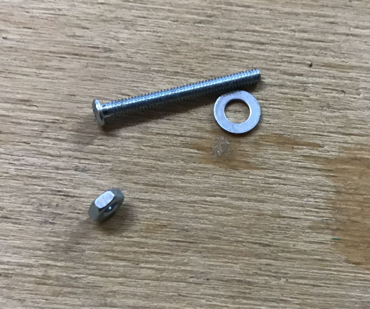
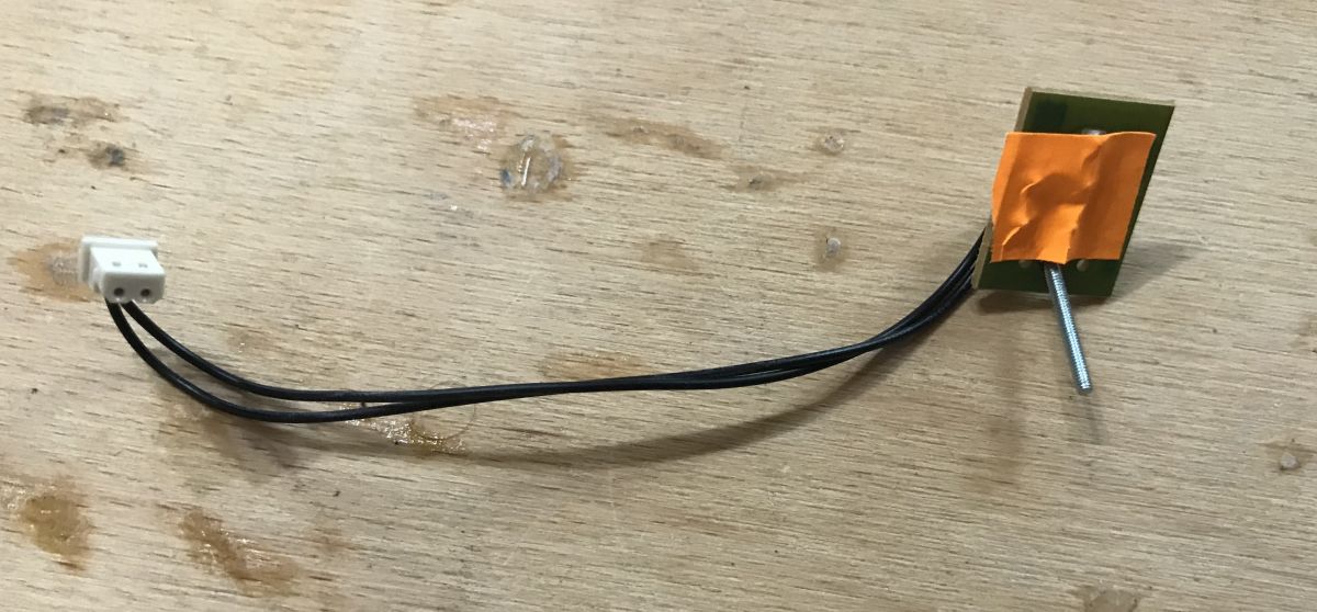
I mounted the element with a small screw:
In addition, I taped it from the PCB side so as not to make a short circuit:
Mounted item:
All that's left is to prepare the code - reading the state of the button and sending it to the UART to check if everything works.
All below:
Code: C / C++
Log in, to see the code
I tested the code in two caret positions.
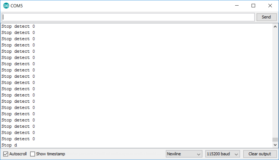
Endstop test - ambulance parked (the button is pressed, so the pin is shorted to ground, so we have 0):
Endstop test - carriage beyond position 0 (the button is not pressed; the pin is not shorted to ground, but there is a pullup - resistor to VCC, so we have 1):
DC motor control via the L298N module We already have:
- encoder support (shift counting based on encoder strip)
- endstop detection support
We don't have engine service yet.
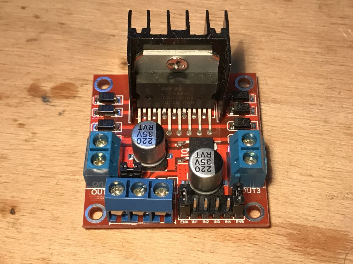
This is a DC motor, the direction of current flow determines the direction of rotation, so you will need an H-bridge. It's best to use a ready-made module. I chose a module based on the L298N integrated circuit:
The module shown above supports two DC motors and is easy to find in many online stores.
It works on voltages up to 35V and currents up to 2A. It will surely be enough.
Diagram of motor connection and its control:
Datasheet L298:
L298_H_Br..ge.pdf (597.3 kB)You must be logged in to download this attachment. As part of the L298 test, I prepared a simple code that only controls the motor - it simply changes the direction of rotation every second:
Code: C / C++
Log in, to see the code
line from analogWrite determines the PWM fill, i.e. the speed of rotation, while digitalWrite for the DA and DB pins determine the direction of rotation.
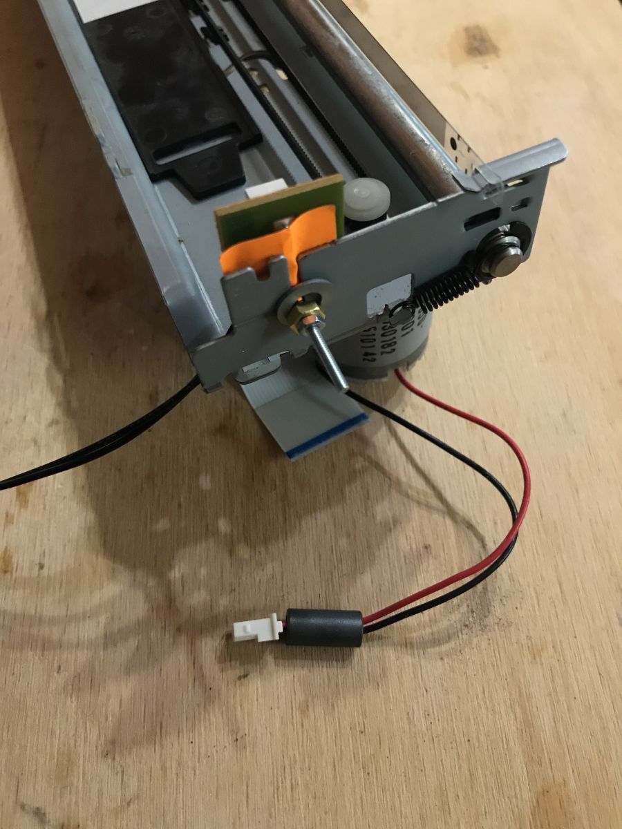
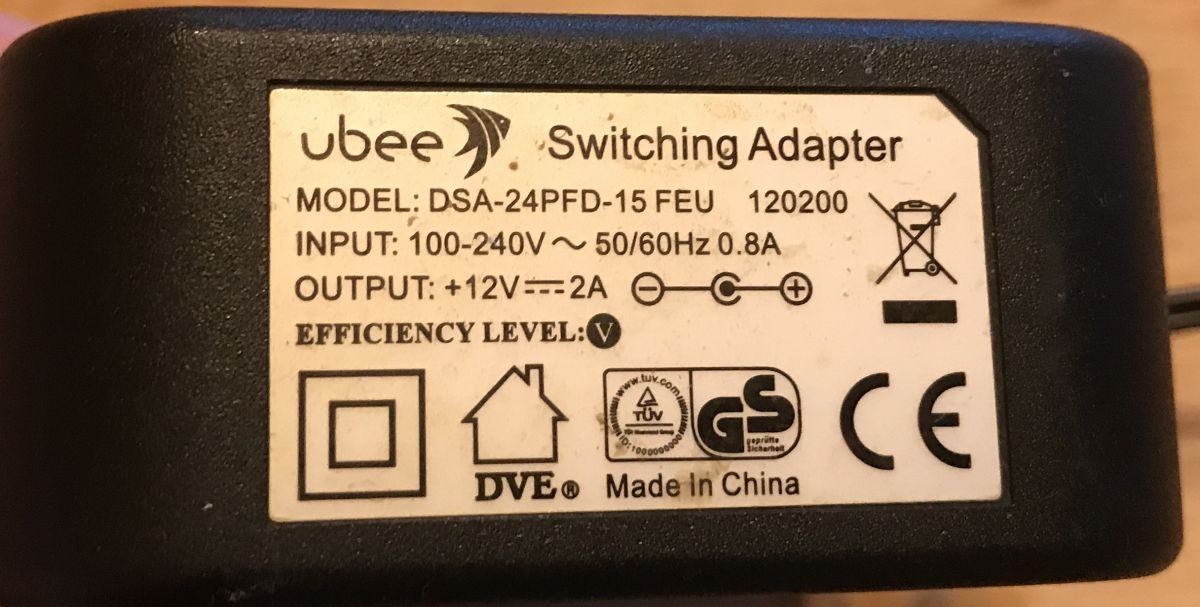
Unfortunately, the 5V voltage here turned out to be too low for the ambulance motor; I had to use a 12V DC power supply:
After it was properly connected, the engine started.
Result in the video:
The carriage is already moving - in the next paragraph I will present a slightly better control of it.
Parking and counting steps with an encoder Then I could prepare a slightly more advanced example that will use the already discussed parking detector as well as the encoder (but only one of its sensors).
The operation of the example is based on handling the current state of the device specified by enumeration command_e .
Variable offset specifies the current position of the caret.
Variable repeats here only helps to detect carriage stop.
Variable prev_encoderA remembers the previous state read from the encoder (high or low), because we need to compare it with the current one to be able to detect the change.
All code below:
Code: C / C++
Log in, to see the code
The example above does not yet support counting the movement on the encoder bar in both directions, I will present it in the next paragraph. Still, everything works fine. what I will show in the videos.
Test with the carriage at the other end of the rail:
Carriage test at the beginning of the rail:
Arduino detects when the carriage reaches the extreme value on the rail and then moves it to the other side. After moving to UART the number of steps counted is sent.
Parking and counting steps with an encoder - on interrupts The code in the previous paragraph begs to be improved to use interrupts - more specifically, the 'on change' interrupt.
On Arduino UNO it is available on pins 2 and 3.
More information here:
https://www.arduino.cc/reference/en/language/functions/external-interrupts/attachinterrupt/ You should use interrupts for such things, not check them every loop like in the previous example. Checking every loop can fail especially if we want to do something in this loop besides checking.
By the way, I also added support for counting encoder steps in both directions - i.e. reading from the second encoder sensor. Details in the code (in the interrupt function):
Code: C / C++
Log in, to see the code
Moves the carriage to the selected position Now you can add a separate 'command' to the code, i.e. moving the caret to a given position. I will implement this in the interrupt handler, I will simply check whether the carriage is behind or ahead of the expected position. The expected position will be described by a variable target_offset .
Full code:
Code: C / C++
Log in, to see the code
Result:
The above code is very primitive. Checking the achievement of the ambulance destination is carried out here:
Code: C / C++
Log in, to see the code
Unfortunately, this solution may not work in many cases - the ambulance will jump over its target by force of momentum and will alternately cause movement to the right and left (once setup_move(0.120) once setup_move(1,120) ).
Here you can combine and, for example, base the engine power on the distance from the target, for example in this way:
Code: C / C++
Log in, to see the code
or put some more serious algorithm to work.
I could also improve the mechanics of this printer carriage, because in my case it has slack on the rail, but I decided that it was acceptable as part of the demonstration. Perhaps I will come back to this project soon and do something more with it.
The code above could also be optimized, even if digitalWrite in Arduino is quite slow (checks the pin index, etc):
Spoiler:
Code: C / C++
Log in, to see the code
They can be replaced with writing directly to the port register (e.g. to PORTB), the operation will be performed faster and the effect will be the same. This is surprisingly a very big change, it gives only one command instead of a dozen or more.
Summary I showed the inside of the printer here HP Deskjet D1360 and I presented how you can handle its encoder and carriage yourself on the Arduino platform. The examples shown could be significantly improved and taken further, and based on them, a more advanced project could be implemented.
Of course, I am fully aware that it is much more convenient to control stepper motors, but the purpose of the topic was to present the operation of the encoder from the printer, not to look for the best solution.
I also have a few scanners with stepper motors waiting to be dismantled, so perhaps I will describe them soon.
About Author
p.kaczmarek2 wrote 14408 posts with
rating 12345 , helped 650 times.
Been with us since 2014 year.
From some of such devices, steppers were also a valuable loot, and when you got a unipolar one, it was cool, because the ULN2803 and any uC was enough to control it, in the era of ready-made modules with... [Read more]
p.kaczmarek2
23 Dec 2020 11:16
I have the impression that in the most budget multifunctional devices, the stepper motor is usually next to the scanner
https://obrazki.elektroda.pl/4961742500_1608718522_thumb.jpg https://obrazki.elektroda.pl/6312588700_1608718553_thumb.jpg... [Read more]
elektryku5
23 Dec 2020 11:35
Scanners usually have them, but the old Lexmark spitter had a crocodile too. [Read more]
SylwekK
23 Dec 2020 11:51
I don't like arduino, but I'll follow the topic, because it's not foreign to me :) In my projects, I usually use DC motors with encoders for their positioning. Such control has a number of... [Read more]
p.kaczmarek2
23 Dec 2020 13:48
I don't prefer Arduino either, but Arduino code is the best way to illustrate how it works and most people will understand it. Doing it, for example, on a PIC (as I would prefer) and/or writing in... [Read more]
Anonymous
23 Dec 2020 18:00
It is enough to wrap it well in functions or macros and it will look legible :)
Such a printer is well suited for the implementation of an inverted pendulum. It will be interesting to see how the arduino... [Read more]
Pablo2015
23 Dec 2020 19:24
Oh yes:
https://www.youtube.com/watch?v=xwXPipYmJ9A&ab_channel=KousheekChakraborty
I don't understand the hate on Arduino. It's bad for what? Because it is simple and more people can program... [Read more]
Anonymous
23 Dec 2020 22:09
Do you really not understand or are you just saying that? I see two sources of hatred of arduino by electronics with longer experience:
- technical - arduino imposes a certain way of thinking about the... [Read more]
klakier2121
24 Dec 2020 09:23
Quite a long time ago I made a whole "printer" on a pen. The carriage from HP is identical to that of the author of the topic, and the positioning of the table is made of a motor with an encoder from the... [Read more]
SylwekK
24 Dec 2020 11:37
A colleague above has already described the "bad" part of the arduino, and I will complete it. The arduino idea may have been right, but it went in the wrong direction. 80% of "electronics" are modular... [Read more]
zulugula
24 Dec 2020 20:17
I also played with such a guide as much as on stm32, they have a built-in quadrature counter. You can have fun with PID, make a simple servomotor. [Read more]
Matheu
25 Dec 2020 07:47
@P.Kaczmarek - thanks for a very simple and accessible article written!
I only have "questions":
and) for encoder tests (readings from both directions)
- in both tables there is the same description... [Read more]
satanistik
25 Dec 2020 08:54
Just a little note - the slotted optocoupler itself is not yet an encoder. [Read more]
p.kaczmarek2
25 Dec 2020 09:50
Arduino is just a good package of functions and macros.
But in general, if someone wants a challenge, they can take the current code and pack it into functions and macros under another microcontroller... [Read more]
Anonymous
25 Dec 2020 21:35
This looks like macro assembler. What compiler are you using it with? [Read more]
What parts are most valuable when stripping a Deskjet D1360?
Keep the carriage rail with dual-channel encoder, two DC motors, end-stop microswitch, separate board-mounted single encoder and assorted screws [Elektroda, p.kaczmarek2, post #19132498] Plastic shell and unsprung metal can be discarded.
How does the printer sense carriage position?
A transparent Mylar strip with 0.1 mm dark lines passes through a slotted opto with one LED and two phototransistors. Quadrature outputs give direction and up to 1 300 counts in the demo [Elektroda, p.kaczmarek2, post #19132498]
What is the correct encoder pinout?
Identify ground first by tracing to board ground. Two adjacent pins are Vcc, the opposite pair are sensor outputs, and the remaining two power the LED [Elektroda, p.kaczmarek2, post #19132498] Pin order varies across printers, so verify with a multimeter.
How should I power the encoder LED?
Use 3.3–5 V through a 150–330 Ω series resistor. Omitting the resistor overheats the LED within seconds, permanently killing the sensor—an edge-case many beginners miss [Elektroda, p.kaczmarek2, post #19132498]
Which motor driver works best?
The L298N dual H-bridge handles up to 46 V and 2 A per channel, enough for the 12 V carriage motor [ST, 2021 datasheet].
Which Arduino pins support external interrupts for this project?
On Arduino Uno, digital pins 2 and 3 support CHANGE interrupts used to read both encoder channels reliably [Arduino Reference].
How many encoder counts equal one full stroke?
In the example sketch, the carriage moved 1 300 counts to the far end stop, corresponding to the entire usable print width [Elektroda, p.kaczmarek2, post #19132498]
What happens if the carriage overshoots the target count?
Momentum can cause ping-pong motion around the set-point. Reduce PWM duty near the target or implement a PID controller to damp movement [Elektroda, p.kaczmarek2, post #19132498]
How do I wire the end-stop switch?
Connect one terminal to ground and the other to a digital pin configured as INPUT_PULLUP. Pressed switch pulls the pin low, giving deterministic zero calibration [Elektroda, p.kaczmarek2, post #19132498]
Can I replace Arduino with PIC or STM32?
Yes. Any MCU offering two CHANGE interrupts and PWM can run the logic. Wrap Serial and digital I/O calls in compatible macros; code ports with minimal edits [Elektroda, p.kaczmarek2, post #19132879]
Is a DC motor with encoder better than a stepper?
DC+encoder offers quieter motion and higher speed; steppers give simpler open-loop control. Choice depends on torque, precision, and cost targets [Elektroda, SylwekK, post #19132672]
Why do budget MFP scanners still use steppers?
Manufacturers keep steppers in scanners for predictable, linear motion, while switching to cheaper DC+encoder assemblies on carriage axes [Elektroda, p.kaczmarek2, post #19132614]
How can I move the carriage to an exact position?
Use an interrupt-driven loop that compares current offset with target. Decrease PWM duty when within 50 counts to avoid overshoot. Full demo sketch achieves ±1 count repeatability [Elektroda, p.kaczmarek2, post #19132498]
Edge case: What damages the encoder quickly?
Cutting the opto coupler body or powering the LED without a resistor destroys alignment or burns the diode, rendering the encoder useless [Elektroda, czareqpl, post #19142206]
What do the salvaged parts cost retail?
Equivalent dual-channel encoder: €3; L298N module: €2; 12 V DC motor: €5. Total replacement cost ≈ €10 versus free when recycled (eBay EU averages, 2024).
3-step How-To: Initialize, park, and move
Attach encoder channels to pins 2 & 3, end-stop to pin 4, motor driver to PWM 11 and DIR 12-13.
On start-up, run motor toward switch until pin 4 reads LOW; reset offset = 0.
Set target_offset, drive motor with proportional PWM until offset == target_offset.


Comments
From some of such devices, steppers were also a valuable loot, and when you got a unipolar one, it was cool, because the ULN2803 and any uC was enough to control it, in the era of ready-made modules with... [Read more]
I have the impression that in the most budget multifunctional devices, the stepper motor is usually next to the scanner https://obrazki.elektroda.pl/4961742500_1608718522_thumb.jpg https://obrazki.elektroda.pl/6312588700_1608718553_thumb.jpg... [Read more]
Scanners usually have them, but the old Lexmark spitter had a crocodile too. [Read more]
I don't like arduino, but I'll follow the topic, because it's not foreign to me :) In my projects, I usually use DC motors with encoders for their positioning. Such control has a number of... [Read more]
I don't prefer Arduino either, but Arduino code is the best way to illustrate how it works and most people will understand it. Doing it, for example, on a PIC (as I would prefer) and/or writing in... [Read more]
It is enough to wrap it well in functions or macros and it will look legible :) Such a printer is well suited for the implementation of an inverted pendulum. It will be interesting to see how the arduino... [Read more]
Oh yes: https://www.youtube.com/watch?v=xwXPipYmJ9A&ab_channel=KousheekChakraborty I don't understand the hate on Arduino. It's bad for what? Because it is simple and more people can program... [Read more]
Do you really not understand or are you just saying that? I see two sources of hatred of arduino by electronics with longer experience: - technical - arduino imposes a certain way of thinking about the... [Read more]
Quite a long time ago I made a whole "printer" on a pen. The carriage from HP is identical to that of the author of the topic, and the positioning of the table is made of a motor with an encoder from the... [Read more]
A colleague above has already described the "bad" part of the arduino, and I will complete it. The arduino idea may have been right, but it went in the wrong direction. 80% of "electronics" are modular... [Read more]
I also played with such a guide as much as on stm32, they have a built-in quadrature counter. You can have fun with PID, make a simple servomotor. [Read more]
@P.Kaczmarek - thanks for a very simple and accessible article written! I only have "questions": and) for encoder tests (readings from both directions) - in both tables there is the same description... [Read more]
Just a little note - the slotted optocoupler itself is not yet an encoder. [Read more]
Arduino is just a good package of functions and macros. But in general, if someone wants a challenge, they can take the current code and pack it into functions and macros under another microcontroller... [Read more]
This looks like macro assembler. What compiler are you using it with? [Read more]
It's destructive, isn't it? [Read more]