SC3-01 SmartLife switch and ESP firmware upload via WIFI (tuya-convert/OTA)
TL;DR
- The SC3-01 SmartLife wall switch uses a Tuya TYWE3S ESP8266 module, and the article covers both its teardown and firmware replacement by Wi‑Fi.
- Tuya-convert runs on Ubuntu 20.04 in a VMware VM with a TL-WN722N USB adapter in AP mode, then flashes Tasmota over OTA without opening the case.
- The board exposes GND, RX, TX, VCC and IO0, includes RF433 hardware, a buzzer, a PN8366 flyback supply, and supports a 512KB firmware image limit.
- The switch boots Tasmota, creates a tasmota-xxxx access point, and the relay, LED, and touch button work after mapping GPIO15, GPIO16, and GPIO5.
- A flashed image overwrites the original firmware, so future OTA updates only work if the new firmware supports them; otherwise UART recovery is required.
AI summary based on the discussion. May contain errors.
 .
.
Hello my dears .
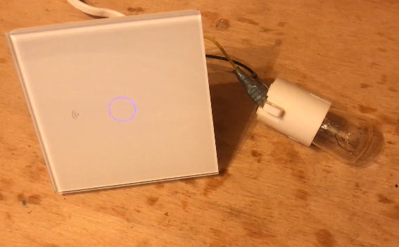
Here I will detail the process of uploading new firmware via WiFi (using tuya-convert) to a Smart Life smart light switch based on a module with ESP8266 (TYWE3S). This is a very convenient way to upload e.g. Tasmota to various smart devices, without having to open and solder them. Of course, the device shown here I will open anyway - to show its interior. To run tuya-convert I will use a virtual machine from Ubuntu set up on VMware and a USB WiFi network card TL-WN722N.
Related topics .
I have already written several topics on WiFi-based ESP products. I mainly show interiors there, list below:
- BW-LT30 or WiFi adapter for bulb - test, teardown and ESP firmware upload .
- WiFi-controlled electrical socket - BW-SHP8 - commissioning and testing
- Test and interior of the BW-SS3, a WiFi controlled light switch from Blitzwolf .
- Socket/plug with WiFi PS-16-M and eWeLink/Coolkit app - test and teardown
- SmartLife switch - test, interior and programming of light switch on WiFi (similar switch, but without RF and description of programming it in Arduino via cables)
In addition, a second topic on Tasmota:
- ESP8266 and Tasmota - WiFi relay control step by step .
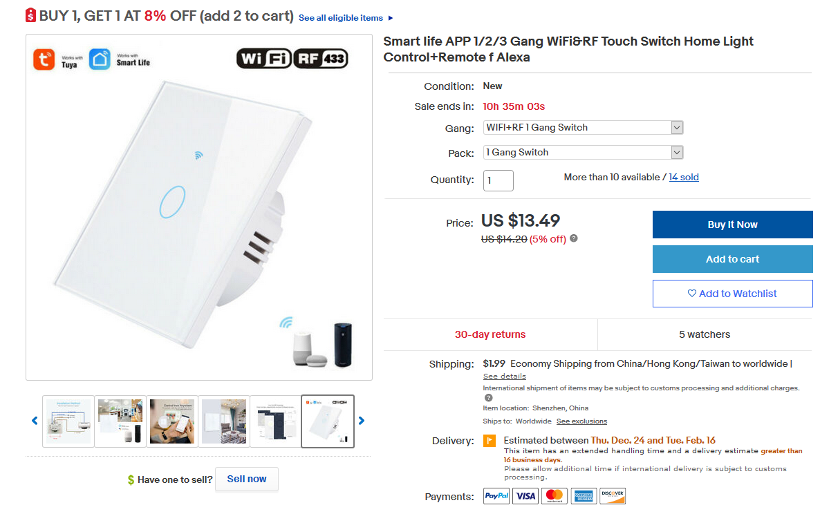
Purchase WiFi light switch SC3-01 .
I found this switch on the internet under 1/2/3 Gang WiFi Touch Switch Home Wall Light Control+ RF Touch Remote Smart Life :
 .
.
It costs around $15, or just under PLN60.
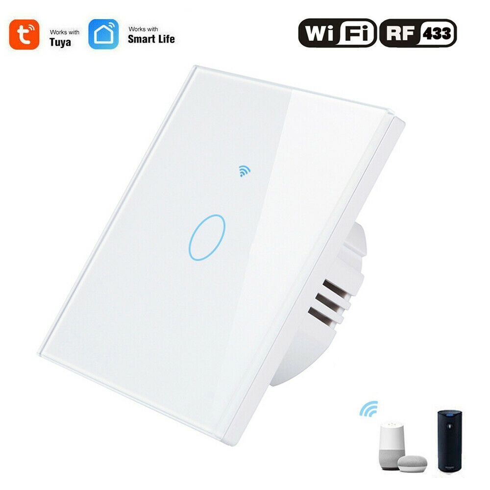
It differs slightly from the switches I have previously tested - in addition to WiFi, it also offers RF433 communication:
 .
.
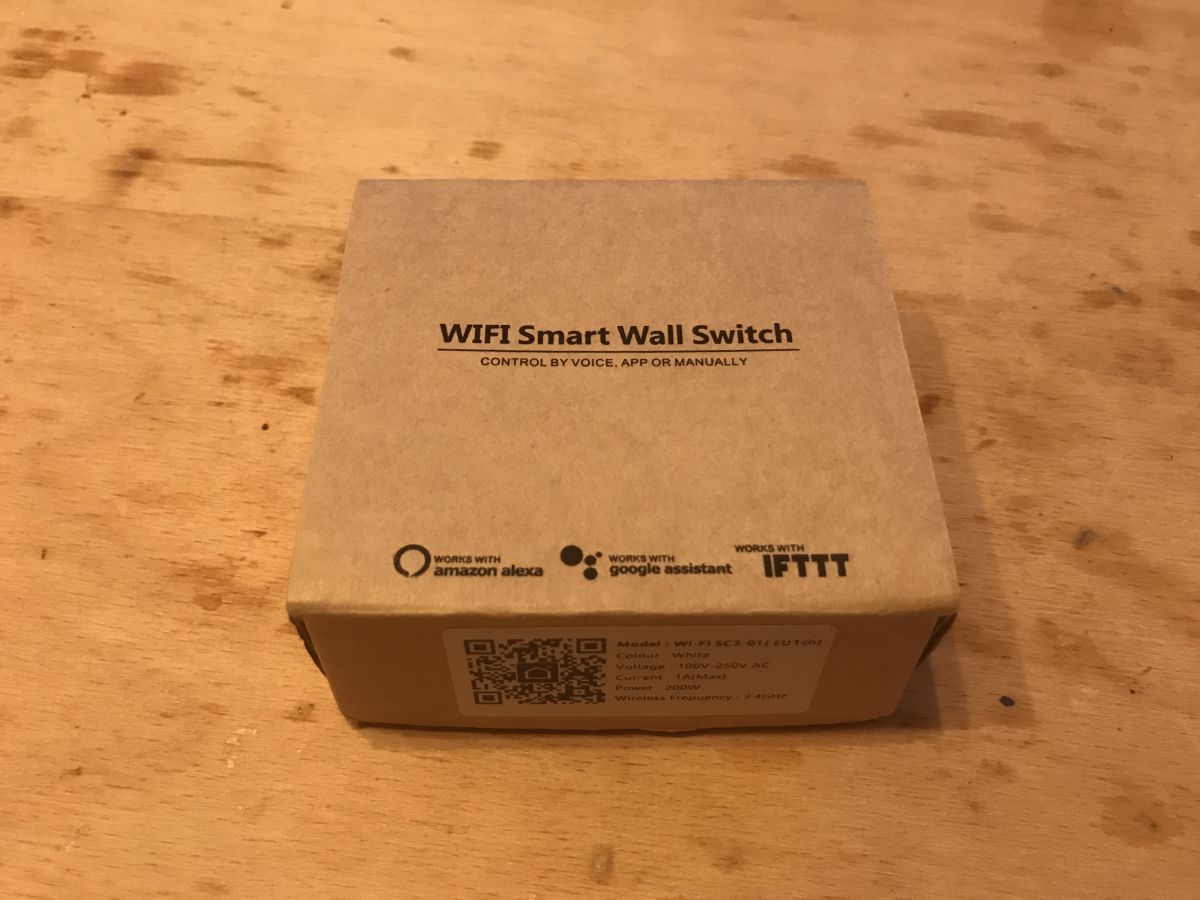
The product was customarily packaged in a cardboard box:
 .
.
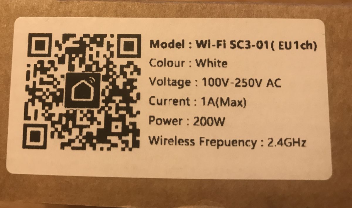
The box shows the model of the switch (this information is not available anywhere else), SC3-01 (EU1ch) :
 .
.
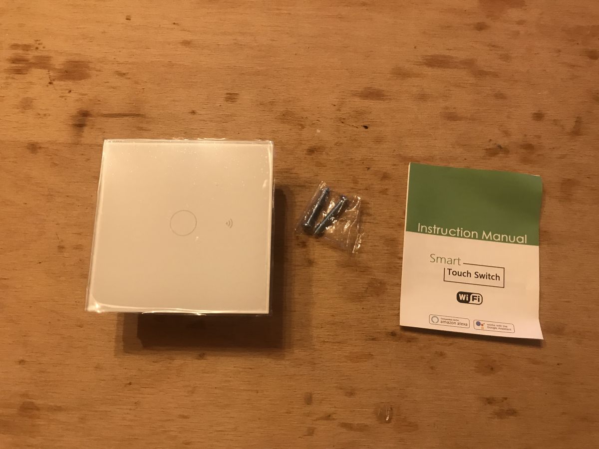
Inside was an on/off switch, instructions, two screws for fixing:
 .
.
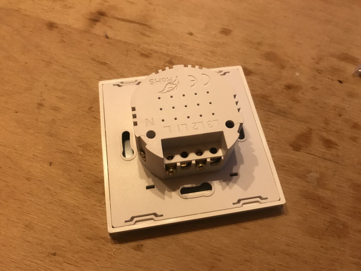
The switch housing is made for the triple version, but in the single version only the middle relay is available:
 .
.
Interior of the SC3-01 WiFi light switch .
This time I thought I'd start by showing the inside (although looking in there is not at all necessary when we're going to upload firmware via WiFi).
Front cover Easy to remove, simply lever it off with a screwdriver:
 .
.
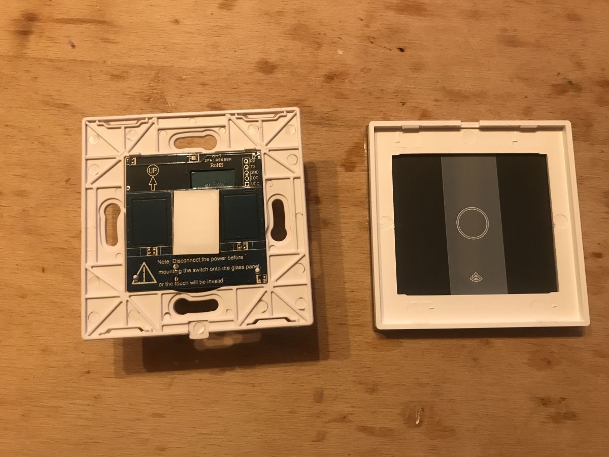
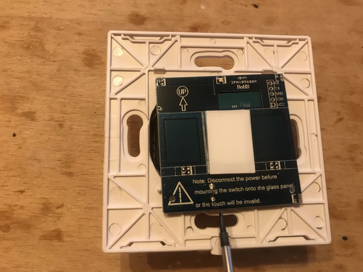
Once it is removed, you can see that the switch plate is thought out for the three-touch version, but only one is soldered on. In addition, it is marked on the board how it should be oriented in the wall (where the top is):
 .
.
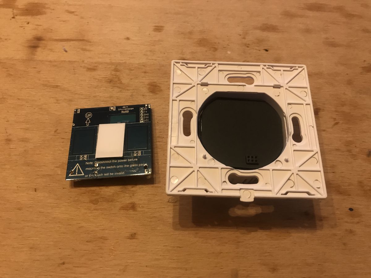
The touch plate is easy to remove, but you have to lever it up from the bottom side as it has catches on the other side:
 .
.
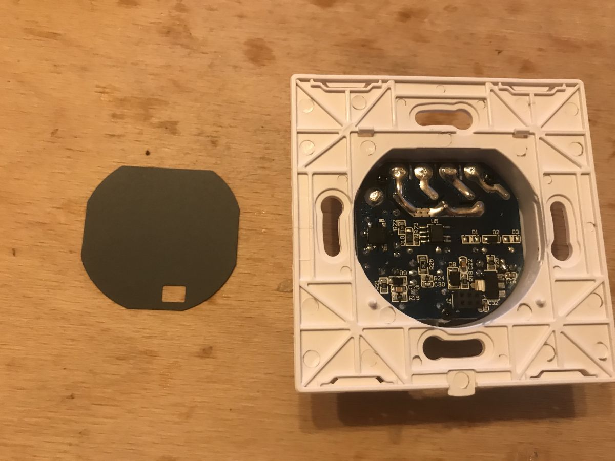
It is fixed with a six-pin (2x3) connector, the other board is covered with black cardboard to avoid short circuits:
 .
.
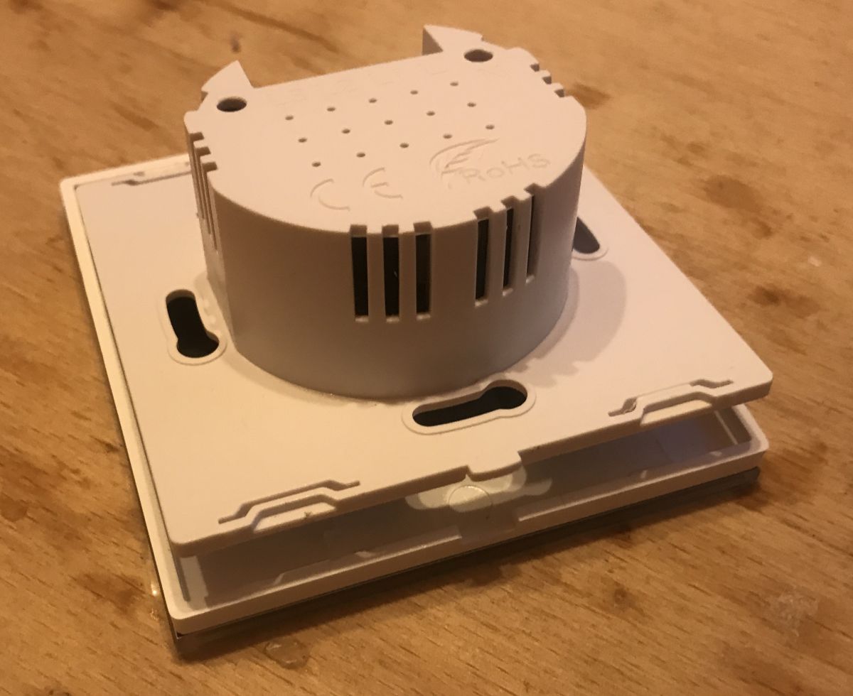
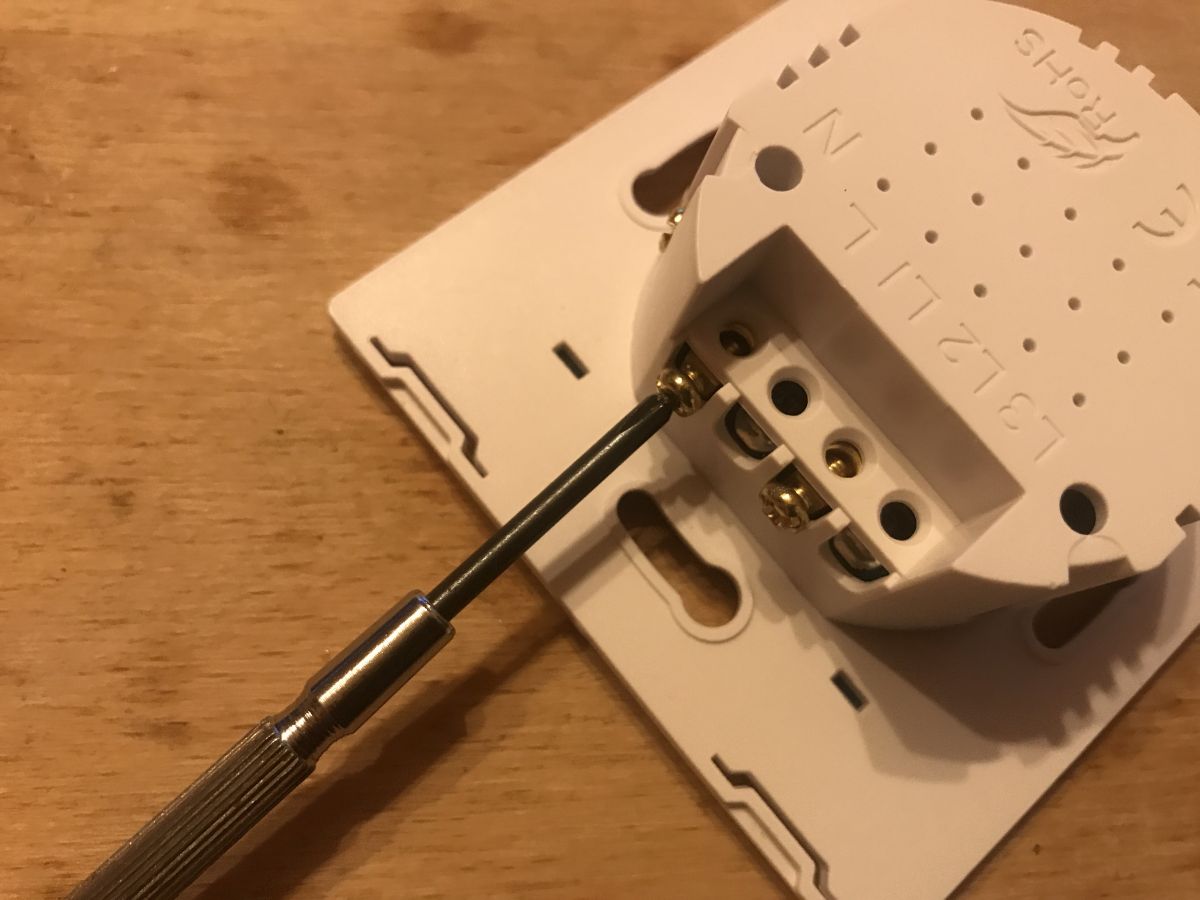
The second plate three screws, is screwed into the socket housing:
 .
.
 .
.
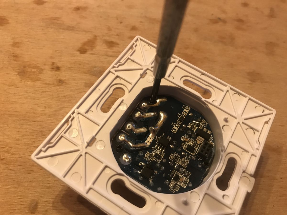
To remove it you also have to unscrew the screws from the wires:
 .
.
Then it can be removed from the inside. The whole set in parts:
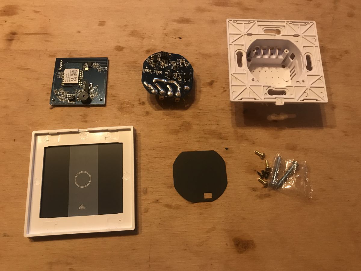 .
.
Now let's take a look at the plates.
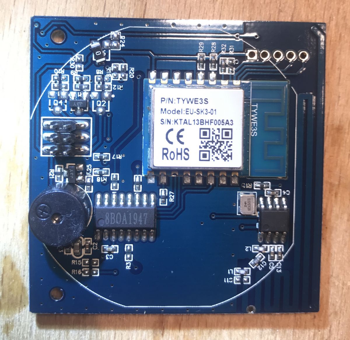
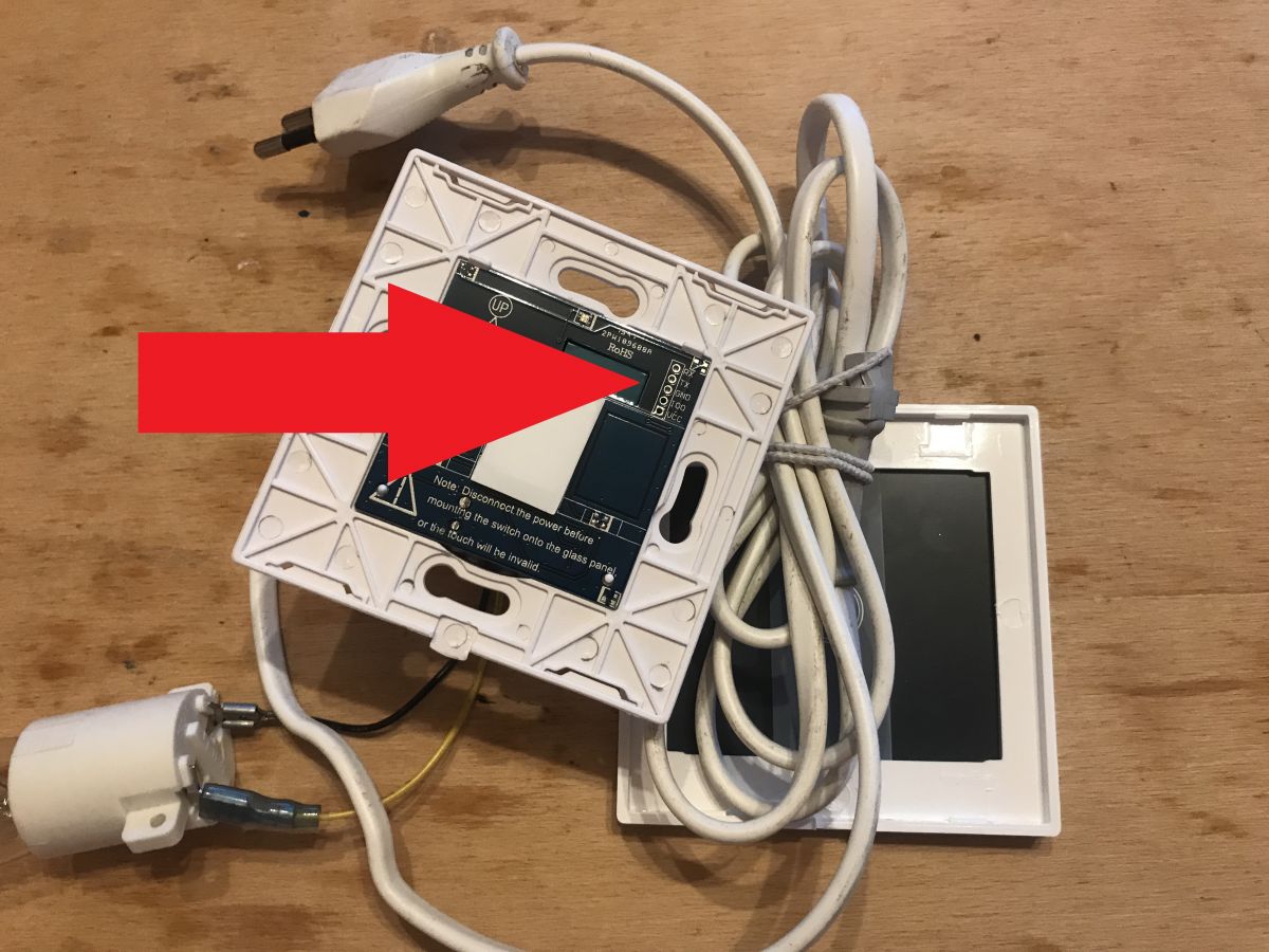
Let's start with the front plate, the one with the touch and WiFi module:
 .
.
 .
.
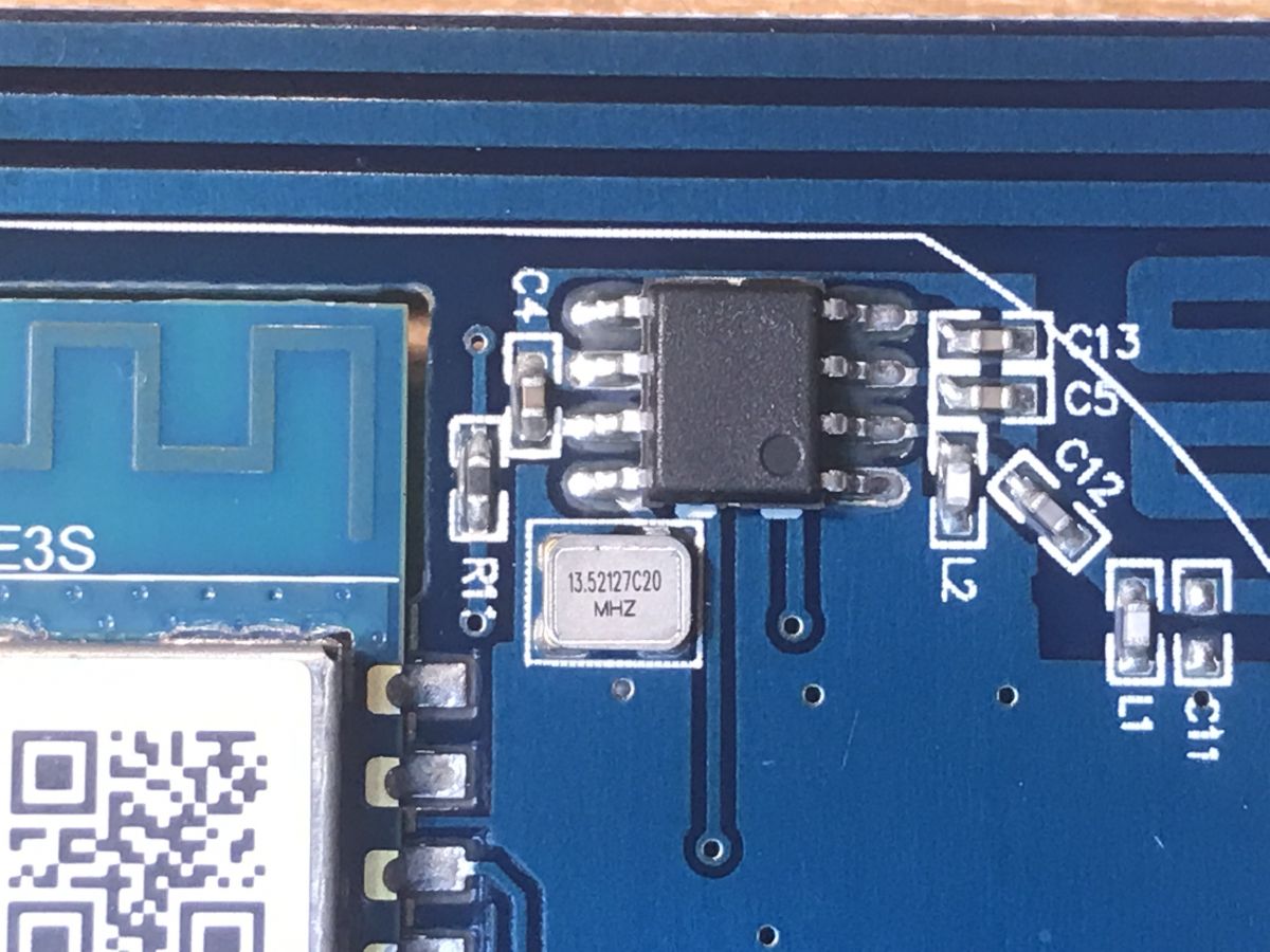
You can see the GND, RX, TX, VCC and IO0 pins derived, which is what is needed to program the TYWE3S. This is a nice change, because with many products we have to get to these signals ourselves, whereas here you just solder 5 goldpins and you're done.
You can of course also see the heart of the board, the TYWE3S module:
 .
.
which is a WiFi module from Tuya based on the ESP8266:
 .
.
The TYWE3S has an antenna on board, but there is also a second antenna right next to it on the board.
This is the antenna from the RF433 communication module which this switch also offers. It is not the second antenna for WiFi.
We also see an unsigned eight-legged IC and a 13.5217MHz clock generator (signed 13.52127C20):
 .
.
Since it's a 433MHz communication module and the clock is 13.52127MHz, it looks like the frequency is multiplied 32 times by the PLL (433.9something/13.5217=32).
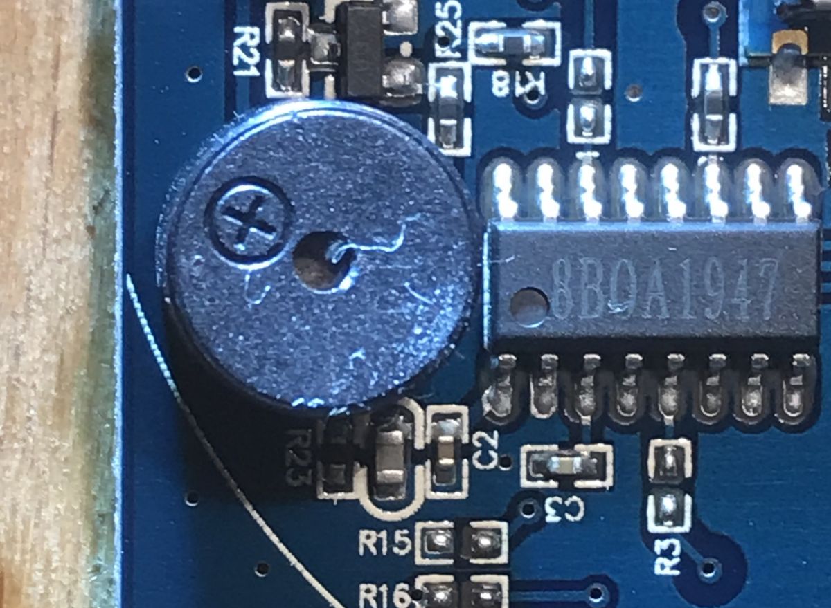
Next to it is another surprise, something not found in previously tested products - a buzzer:
 .
.
Next to it is the 8BOA1947 integrated circuit.
I could not find its datasheet, perhaps it is a touch button controller. The TYWE3S will not handle the touch button by itself, in the previous two similar products I disassembled there was an IC responsible for touch.
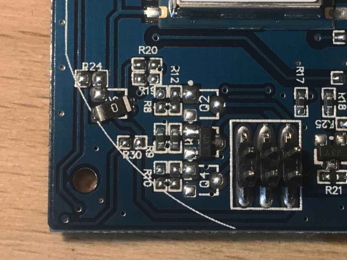
At the 2x3 pins connecting the two boards, you can see one transistor code JY3 and two free spaces:
 .
.
These are the transistors that control the relays. There is only one here because it is a single switch version.
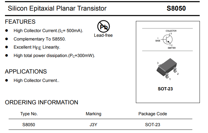
The transistor J3Y is an S8050:
 .
.
You can also see a 0ohm resistor, or jumper, soldered in a strange way. This is located on the pad under the transistor:
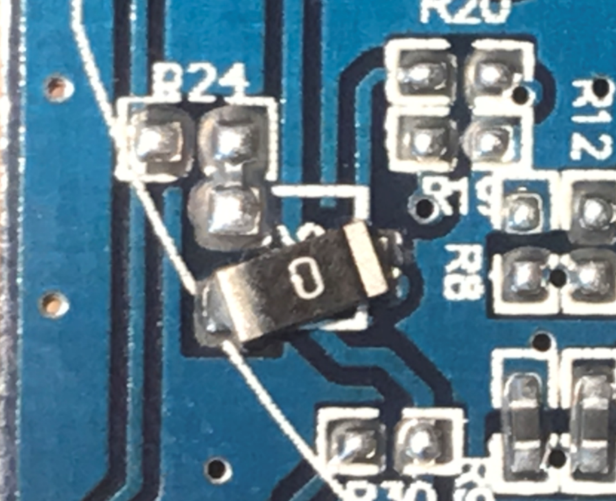 .
.
There is nothing else interesting on this board, now it is still worth dissecting the pins from the 2x3 connector:
Quote:..
Pin 1 - 3.3V
Pin 2 - GND
Pin 3 - GND
Pin 4 - (?second/third relay?)
Pin 5 - middle relay
Pin 6 - (?second/third relay?)
Pin one is marked on the PCB. Everything as expected. By "relay" I mean not the signal from TYWE3S itself, but already behind the transistor because the transistors from the relays are also on the front PCB. On the rear PCB are the relays together with the surge protection diodes, without the transistors.
The second plate can now be looked at:
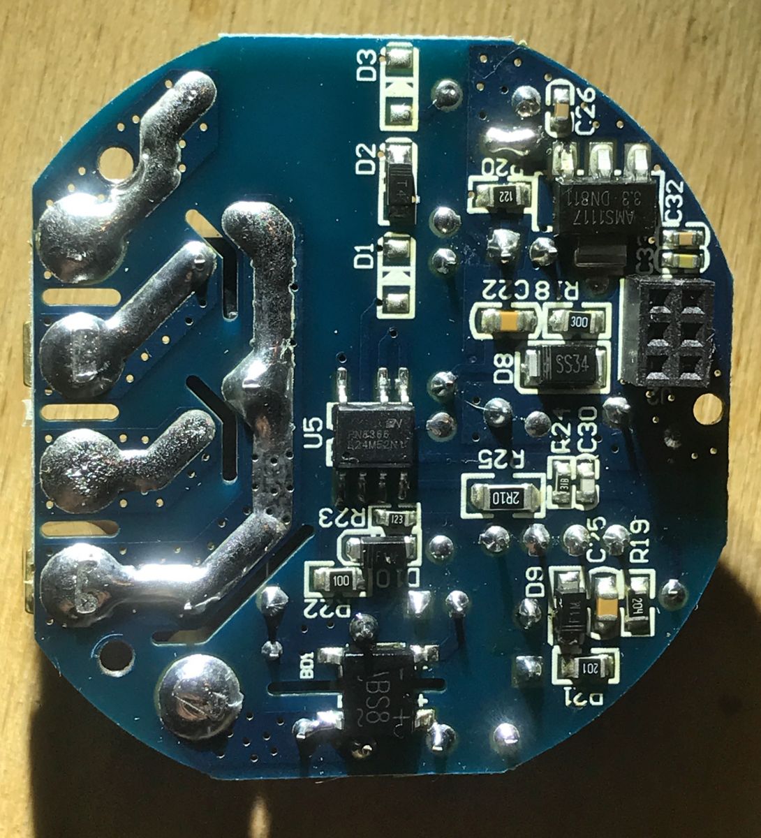 .
.
 .
.
These diodes D1, D2 (soldered), D3 are diodes from relays, connected in parallel to their windings:
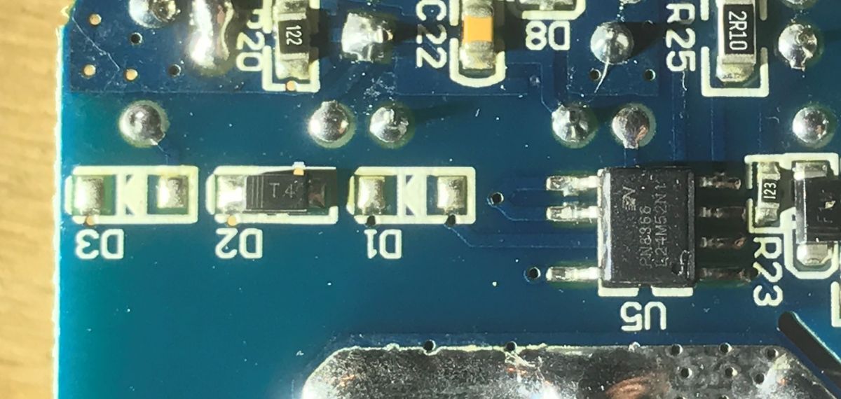 .
.
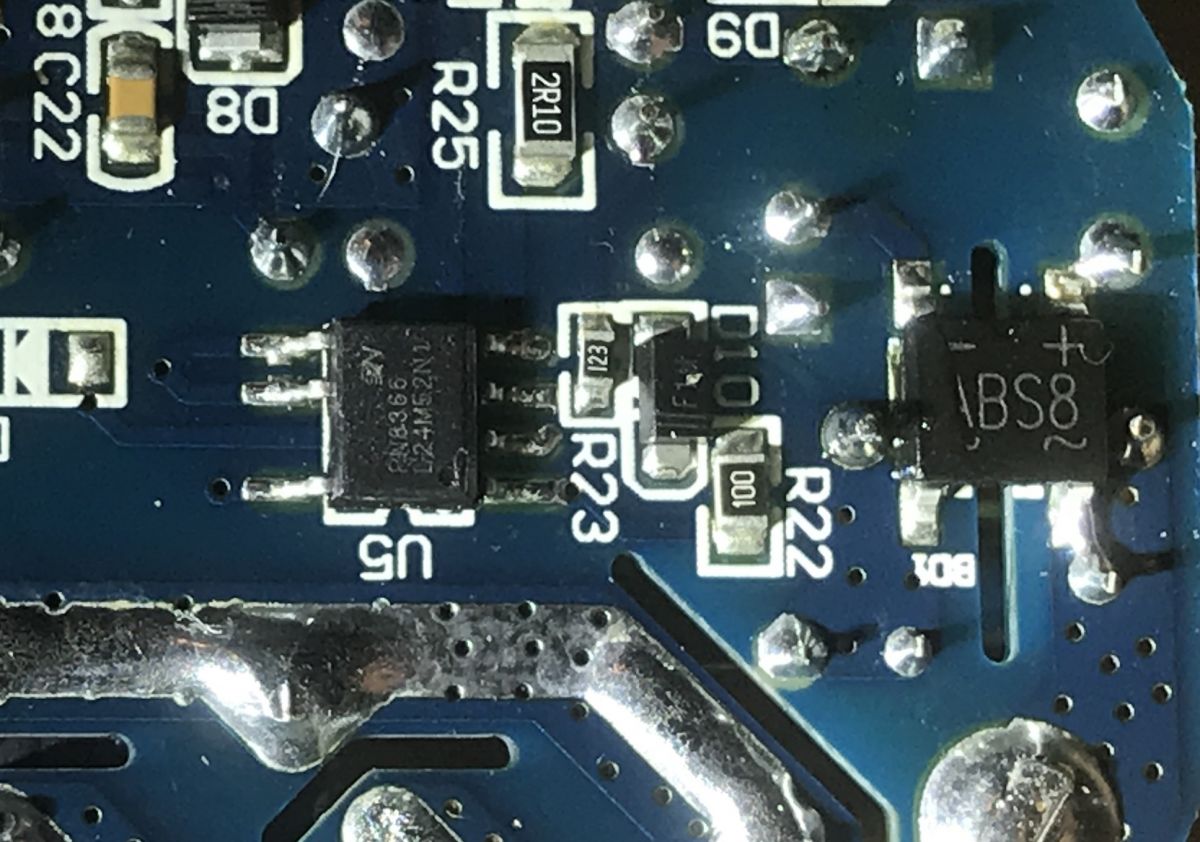
On this board is a small switching power supply in flyback topology. It is based on the PN8366 chip:
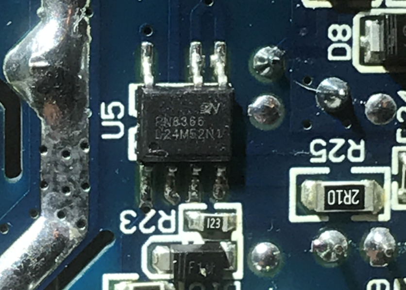 .
.
An example PN8366 application (the power supply here probably looks more or less like this):
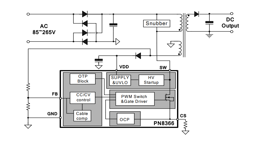 .
.
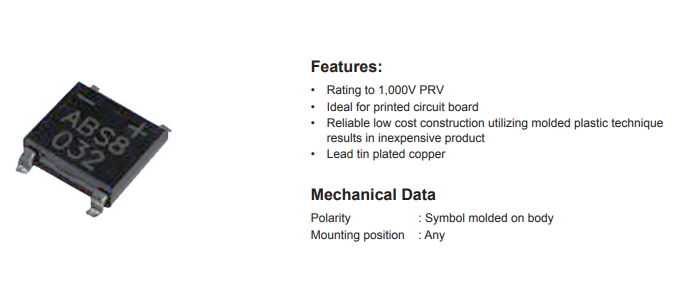
Right at the mains connection is an ABS8 rectifier bridge (800V, 0.8A):
 .
.
 .
.
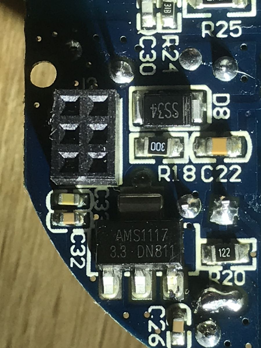
There is a Schottky diode SS34 at the output of the power supply (it rectifies the output from the secondary winding of the transformer; a Schottky diode was specifically used here because it has a low voltage drop):
 .
.
Behind it is the AMS1117 3.3V voltage regulator:
 .
.
 .
.
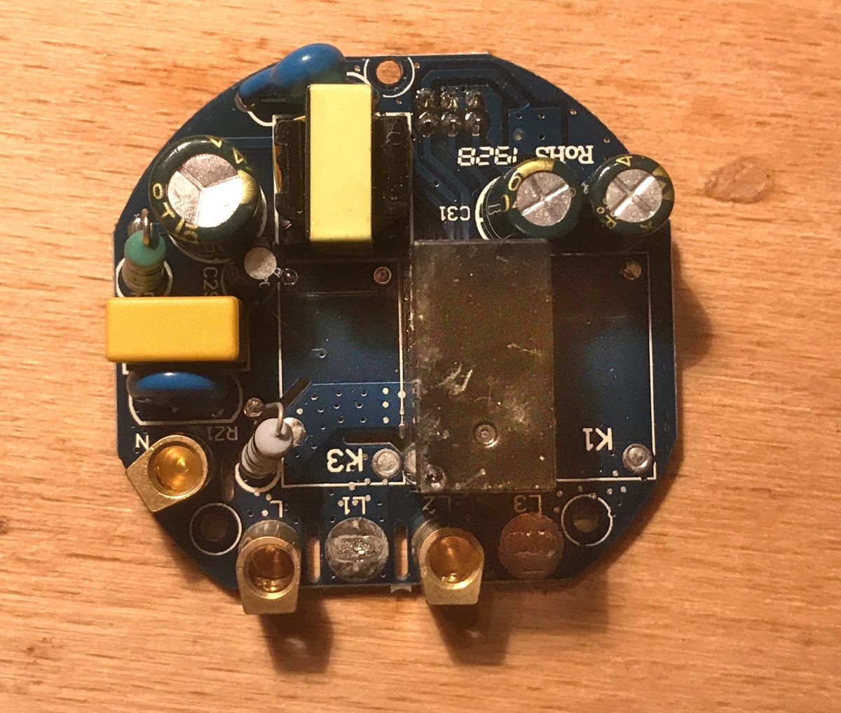
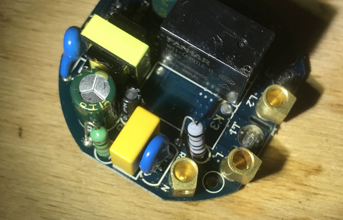
From the top of the board, the most striking features are the relay (W11-1A2STLE-H DC5V 10A 250VAC/30VDC CHINA CQC) and the small pulse transformer from the power supply:
 .
.
 .
.
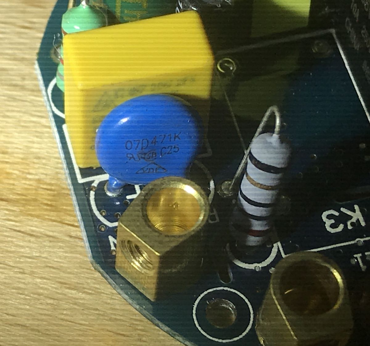
The 07D471K varistor and fuse resistor can also be seen:
 .
.
Tuya Convert - introduction .
Tuya Convert is a script (written in Python) that allows you to upload firmware over a WiFi network for a number of Tuya production devices, mostly based on the ESP8266.
That is, with Tuya Convert, we don't even need to open the device's case, let alone solder anything. All we need to know is that the device is based on a Tuya module (otherwise it won't work).
Project repository:
https://github.com/ct-Open-Source/tuya-convert
Repository backup:
.
It is worth noting here that Tuya-convert is independent of our preferred smart home firmware for ESP. It is in no way linked to Tasmota or thereabouts Domoticz.
The only thing to remember is that after uploading a batch via Tuya-convert, the previous batch is overwritten by Tuya-convert, so if you upload something without the possibility to update via WiFi, you won't be able to update this batch a second time afterwards (there will be no way to connect) and you will have to solder after all.
NOTE: I do not recommend any booting and pairing with WiFi of the IoT device before using tuya-convert. There is a risk that the device will then download an update from the manufacturer, which tuya-convert does not support, and we will then be condemned to soldering and cables, however.
Tuya Convert - What will we need? .
It really doesn't take much to get started. You will only need a few things:
- a home WiFi router (rather most of us have one) to which we know the password
- a smart home device based on a supported module with ESP from TUYA (before buying a smart device, it is worth searching on the web to see what is in it, Tuya produces TYWE3S, TYWE2S, etc. modules)
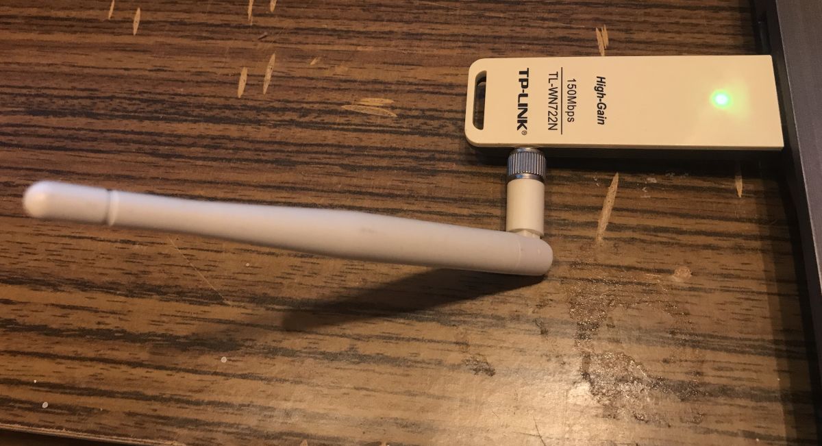
- a USB WiFi network card capable of operating in Access Point mode (pretending to be a WiFi router) - I used TL-WN722N (cost ca. PLN 40)
- a phone or any device capable of connecting to a WiFi network
- a computer with Ubuntu or a related system, or. a Windows PC with VMware on it to set up a virtual machine with Ubuntu (the tuya-convert authors also recommend using a Raspberry Pi, but I don't think everyone has one, so Ubuntu is a better option)
Tuya Convert - installing the necessary stuff .
I will describe here step by step what is needed to run the tuya-convert script.
I perform the steps outlined here on a VMware virtual machine, but you could just as well do it on a normal computer.
First of all - the system. I've chosen Ubuntu 20.04, to be precise:
ubuntu-20.04.1-desktop-amd64.iso .
I downloaded it via torrent/P2P network (Ubuntu is a free system, you can download it legally). Magnet link:
Spoiler:
.
.
magnet:?xt=urn:btih:2EIBUK45EAUBDIC6RRL4KV5CBP4XJXEK&dn=ubuntu-20.04.1-desktop-amd64.iso&tr=https%3A%2F%2Ftorrent.ubuntu.com%2Fannounce&tr=https%3A%2F%2Fipv6.torrent.ubuntu.com%2Fannounce&net=Public&net=I2P&net=Tor
magnet:?xt=urn:btih:2EIBUK45EAUBDIC6RRL4KV5CBP4XJXEK&dn=ubuntu-20.04.1-desktop-amd64.iso&tr=https%3A%2F%2Ftorrent.ubuntu.com%2Fannounce&tr=https%3A%2F%2Fipv6.torrent.ubuntu.com%2Fannounce&net=Public&net=I2P&net=Tor
(you need a Torrent client to download Ubuntu via the magnet link, although you can also download it normally via the WWW) .
I performed all the operations described below on a clean, just-installed system.
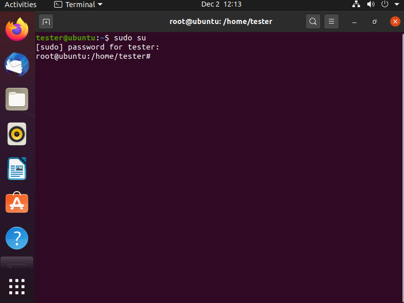
First - a formality, entering root mode (beginners forget about it), sudo su :
 .
.
Then version check (command lsb_release -a ):
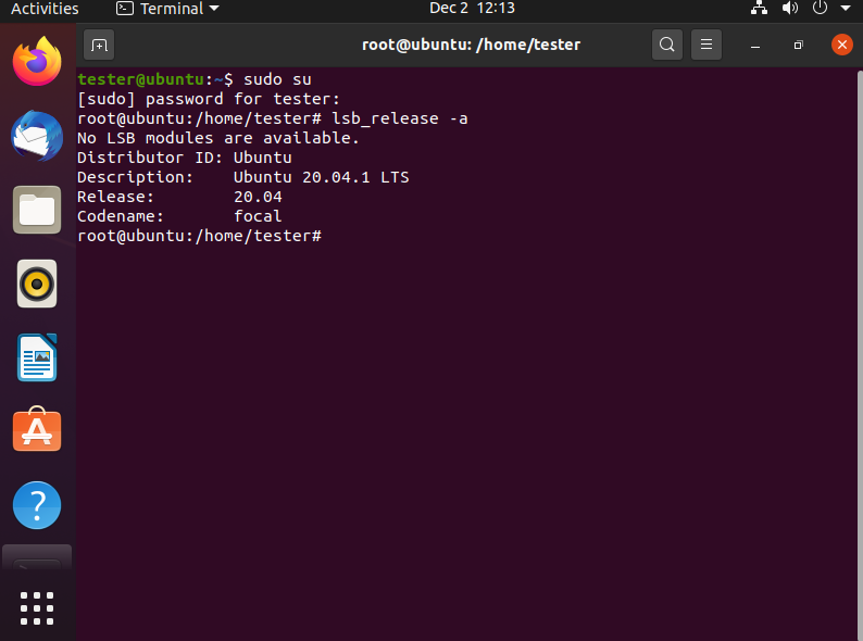 .
.
This is especially for you - if you have an older version, something may go wrong. I was not able to run tuya-convert on Ubuntu 16, there were problems with Python.
Then you can do an update ( apt-get update ):
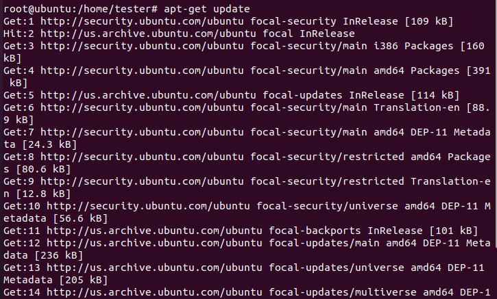 .
.
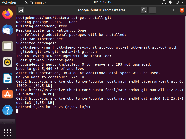
We will now install git, the version control system, to be able to perform a git clone i.e. download the tuya-convert repository. Command apt-get install git .
 .
.
Once installed, we can check if git is working by simply querying it for its version, command git --version :
In my case it was version 2.25.1, but you guys can have a different version, it's no problem.
Tuya Convert - installation of Tuya Convert .
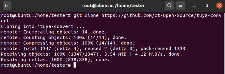
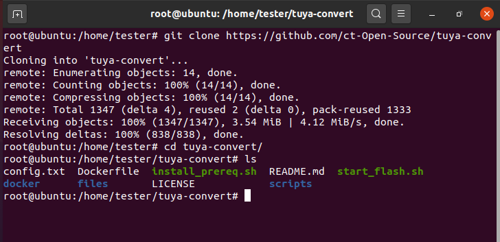
We have everything we need, we can download the Tuya-convert repository via git. We type git clone https://github.com/ct-Open-Source/tuya-convert .
 .
.
Git will download the repository and create a folder for it.
We navigate to the created folder, we can list its contents: cd tuya-convert and then ls :
 .
.
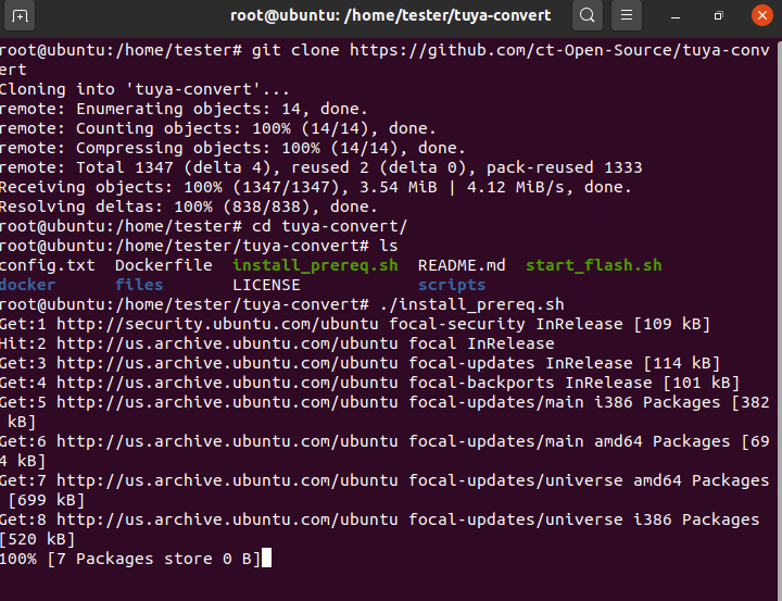
Run the script ../install_prereq.sh :
 .
.
Ubuntu downloads the required packages, this will take a few minutes. The installation should be successful:
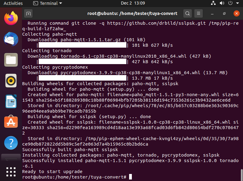 .
.
Tuya Convert - we are connecting the USB wireless adapter .
We can now connect our WiFi dongle (in my case it's the TL-WN722N):
 .
.
If we're using VMware, we also need to make sure it's connected to the virtual machine and not to our main computer. We look in VM->Removable Devices.
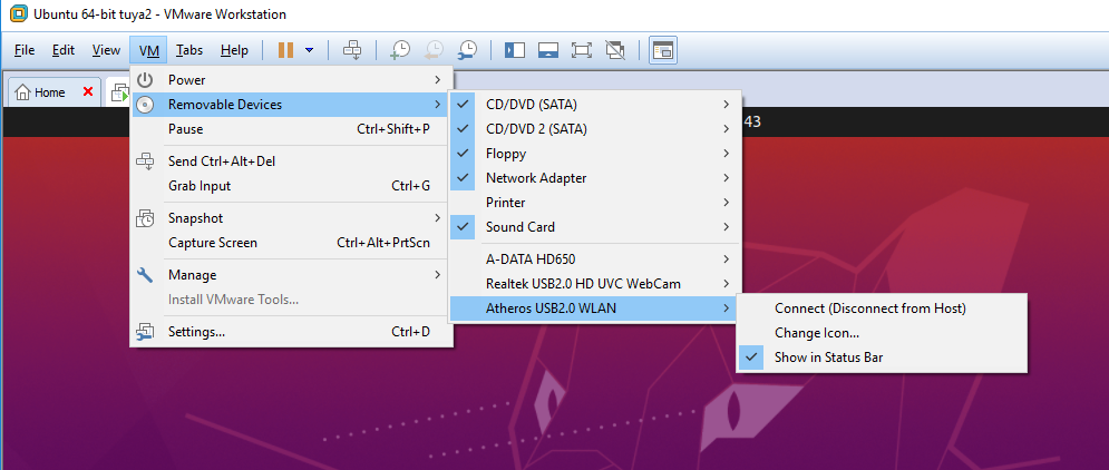 .
.
In the screenshot above, the Atheros USB2.0 WLAN adapter is not connected to the VM. You have to click 'Connect (Disconnect from Host)' to connect it. Only then will Ubuntu see it.
The visibility of the USB device by Ubuntu can also be checked with the command lsusb :
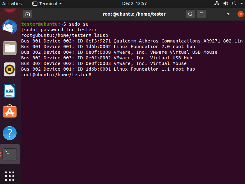 .
.
The USB network card should be visible there. In my case it shows as Bus 001 Device 002: ID 0cf3:9271 Qualcomm Atheros Communications AR9271 802.11n .
Tuya Convert - Tuya Convert configuration .
The script requires the network interface that will be used to make the AP for the device being converted to be indicated by. This is specified in the config.txt file.
The list of available network interfaces on Linux can be found out with the command ifconfig :
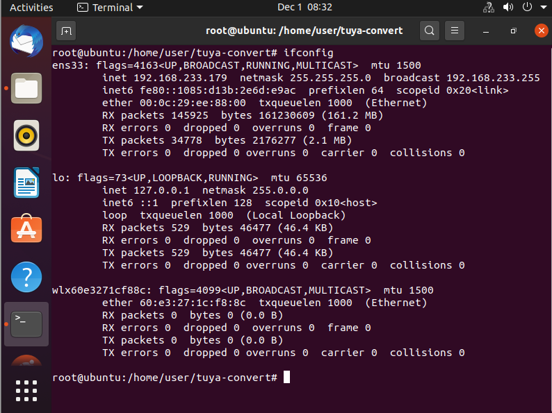 .
.
In this list, you should be able to see the USB wireless card we have connected.
And now we basically have two options:
- either enter the name of our interface into the configuration script
- or change the name of our interface to what the script expects.
Entering it into the configuration can be done very simply, via the text editor gedit . It can be run normally via file explorer, or via the console:
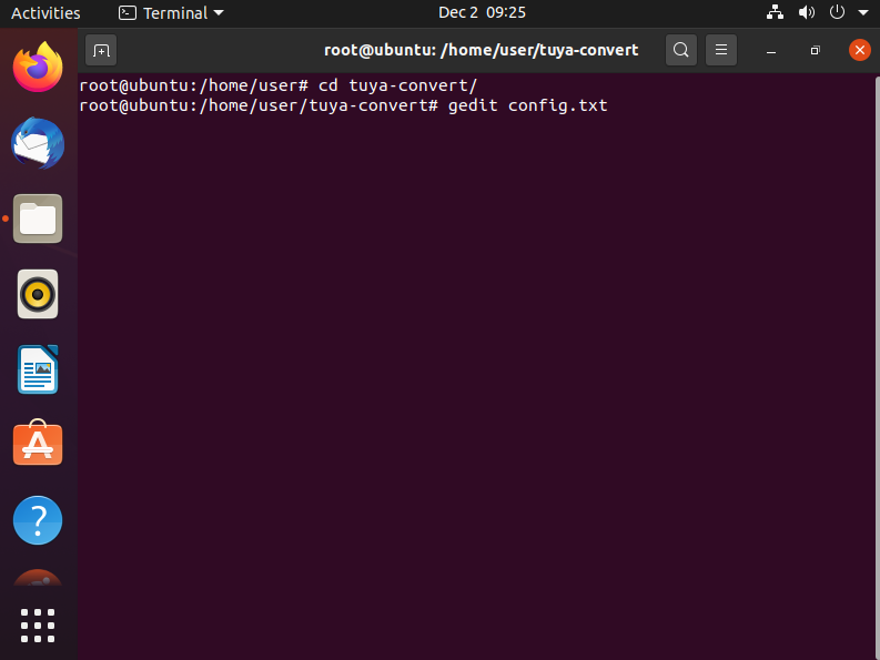 .
.
Of course, there are also text editors such as nano or vi , but I do not recommend them in order not to scare beginners.
Contents of config.txt:
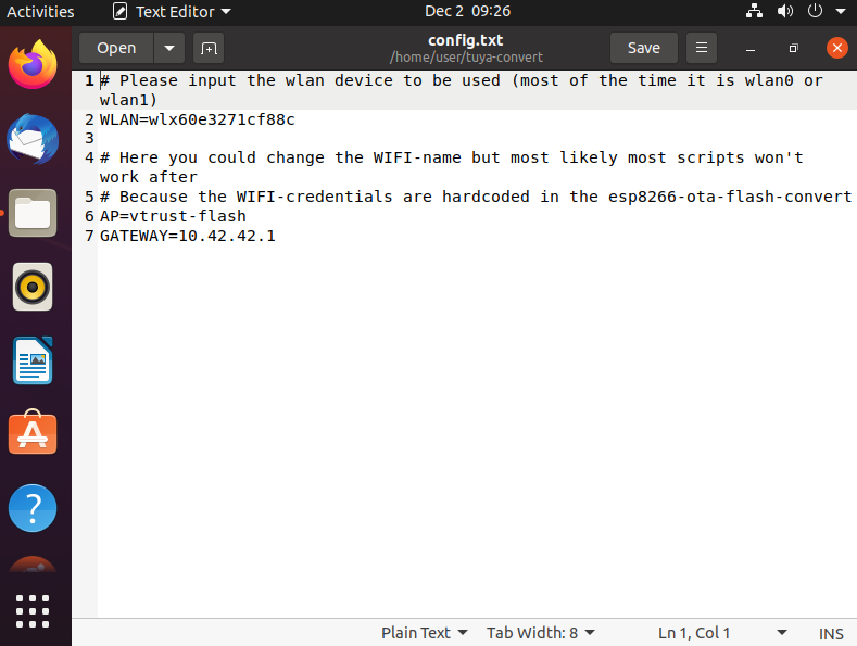 .
.
After WLAN= should be the name of our network interface.
Changing the interface name, on the other hand, comes down to the commands:
- ip link set wlx60e3271cf88c down - to temporarily disable the interface.
- ip link set wlx60e3271cf88c name wlan0 - to rename it
- ip link set wlan0 up - to turn it on again
This ' wlx60e3271cf88c ' is of course the name we have rewritten from the result ifconfig , with you it may be different.
Now we have everything we need and we can run the script.
Tuya Convert - uploading TYWE3S firmware over WiFi .
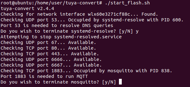
Run the script by typing ./start_flash.sh (you must be in its folder):
 .
.
The script may ask us for permission to force the termination of processes occupying the necessary ports for it. We grant it with the Y key.
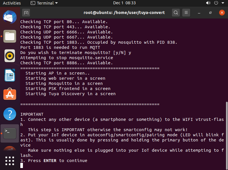
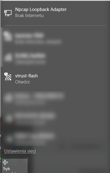
The script should then create a WiFi network named vtrust-flash and ask us for actions:
First we verify that the network has indeed been created:
 .
.
Then we connect with any of our devices (e.g. a phone) to this network:
 .
.
We then reset our smart device using the method described in its instructions (usually a longer press on the touch):
At this point we can already click ENTER and proceed to the merging stage. First, tuya-convert will back up the firmware from the device:
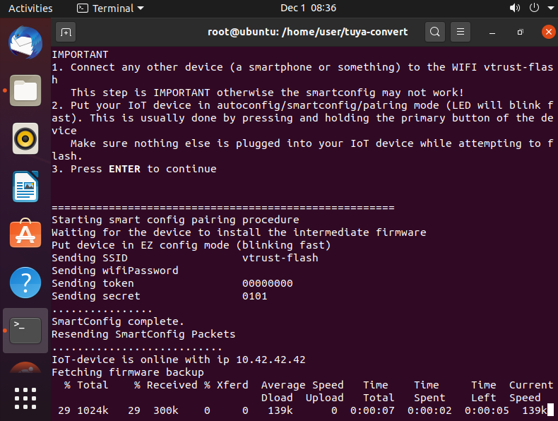 .
.
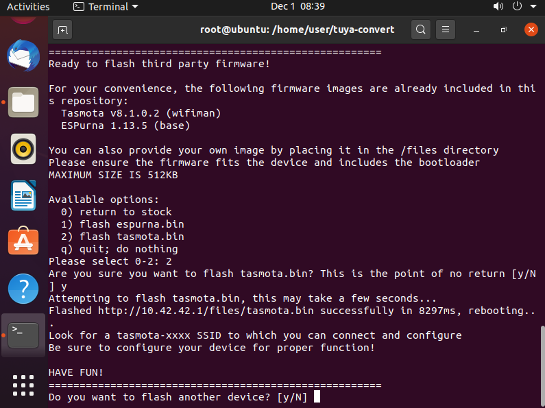
Then it will give us the choice of which firmware to upload:
 .
.
The firmwares from the list are loaded from the "firmware" folder, we can also put our own firmware there, but we have to remember that if it does not support the possibility of updating via the network, we will not be able to change it later (well, unless we open the switch casing and connect to it with cables, programmer).
We must also remember the firmware size limit, here 512KB. When updating the batch, the FLASH memory from the ESP must store both the new (downloaded) batch and the current, current one.
I decided on Tasmota v8.1.0.2 (wifiman) :
 .
.
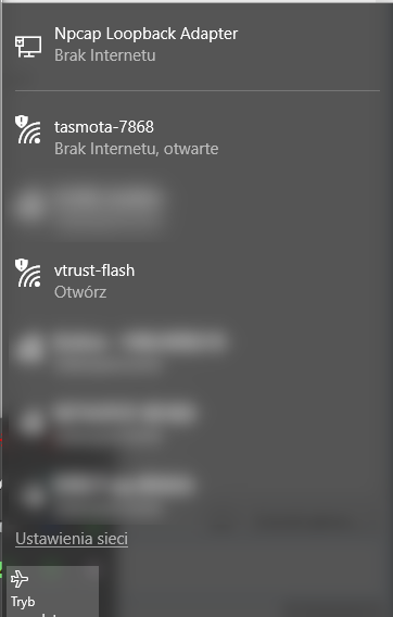
The batch was uploaded correctly over the network. The ESP8266 restarted and has now created its own Access Point with the name tasmota-xxxx (instead of xxxx a random number).
Tasmota - configuring the SSID and password of our WiFi network for the Tasmota .
At this stage, the Tasmota device does not yet know how to connect to our WiFi. We need to give it the SSID and password of our network ourselves.
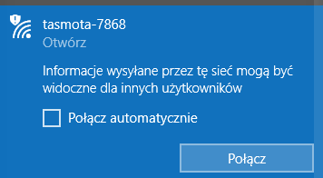
To do this, we connect to the WiFi network created by our device named tasmota-xxxx:
 .
.
This network does not require any password:
 .
.
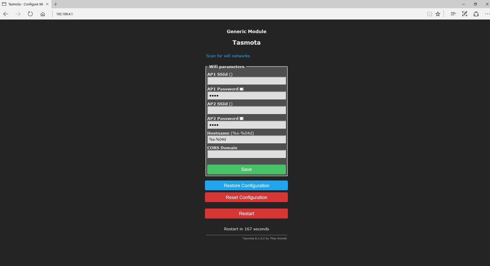
Once connected, navigate in your browser to the IP address 192.168.4.1. This is the default IP address used only for the first stage of configuring the device:
 .
.
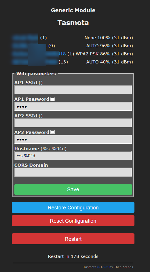
On this page we enter for Tasmota the name of our WiFi network and its password. We can also provide optional information about a second, backup network. There is also a "Scan for wifi networks" button on the page which shows us what WiFi networks the ESP sees along with their signal strength:
 .
.
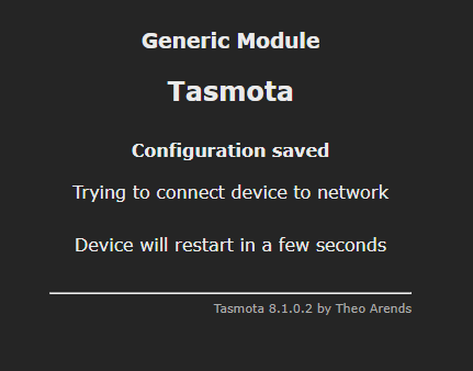
After entering the data we click Save and then Restart to restart the device:
 .
.
We will then lose the connection to the tasmota-xxxx WiFi network, but this is not a problem. We will not need it. From this point on, the Tasmota device will already connect normally to our router (already as a client). Now we can also connect back to our WiFi network.
Tasmota - determining the IP address of the Tasmota device .
Now we still need to determine what IP address our router has assigned via DHCP for our new Tasmota device.
There are several ways to do this.
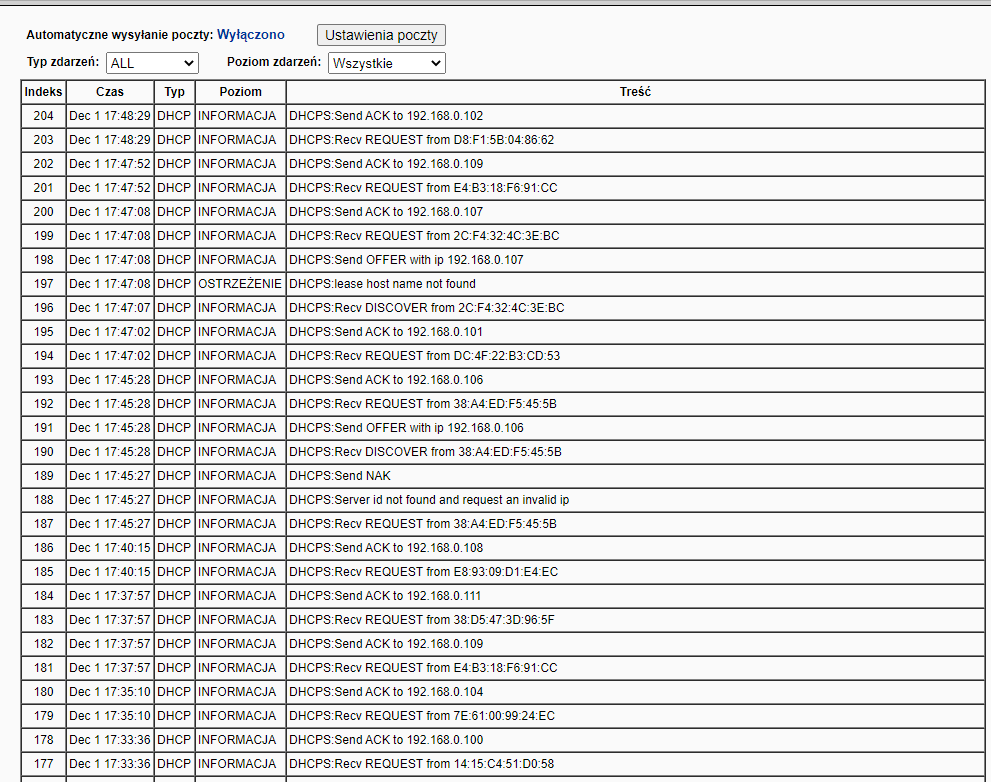
We can log into our router's admin panel and look at the recent logs there, look at what IP addresses have connected to it in the last few minutes:
 .
.
This already narrows down our search to a few IPs.
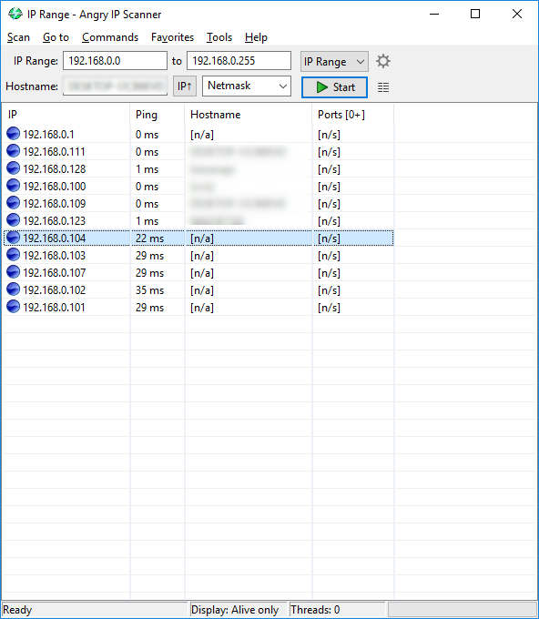
But you can also use an IP scanner (such as Angry IP Scanner):
 .
.
The Tasmota device should also have a specific hostname (not n/a, as in my screenshot), but in my case this did not work.
I found my switch under IP 192.168.0.107:
 .
.
Now we have a location for the switch, we can move on to configuring it.
Tasmota - initial familiarisation with the web panel .
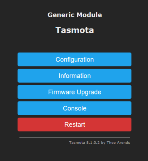
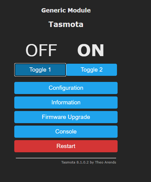
Each Tasmota device has a web panel as shown in the image below:
 .
.
I will now tentatively discuss the options available in it.
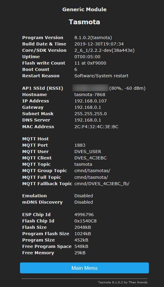
Information button shows us information about this device:
 .
.
This includes
- information about the network to which the device is connected
- information about the device itself (IP address, MAC address)
- information about the ESP (memory size, Flash chip ID)
- information about MQTT (I have not used it at this stage)
- information about the Tasmota version (can also be updated via WiFi, without tuya-convert of course)
- information on how long the device has been running since the last power-on (so-called uptime), the number of times it has been started (boot count) and even the reason for the last reboot
Firmware Upgrade button allows us to update the ESP batch over the network:
 .
.
New firmware can normally be sent as a file from your computer, or you can simply provide a link to firmware available on the internet and then ESP will download and upload it itself.
(but as I mentioned before; as with tuya-convert; the new firmware also has to support the ability to update via WiFi, otherwise you have to solder .
Console button gives us access to the console of this device:
 .
.
There is an event log and the Tasmota command line available here. Fortunately we won't need to use it, we'll configure everything via the web interface, but that's later.
The Configuration button allows us to configure Tasmota for our specific device. Here we specify exactly how many relays, buttons etc we have, and which ESP pins they are on:
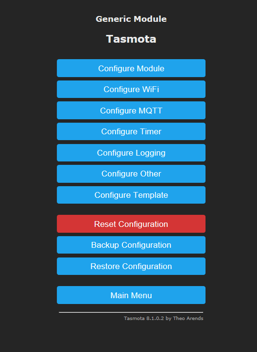 .
.
We can specify this ourselves or use a ready-made template. Tasmota templates are available, among others, here:
https://templates.blakadder.com/
The template is pasted in Configure Template:
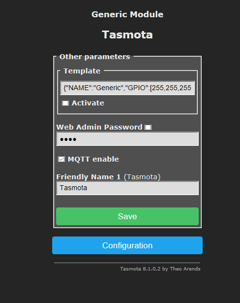 .
.
But developing the template yourself is not a problem either. We can freely configure pin roles on the Configure module tab :
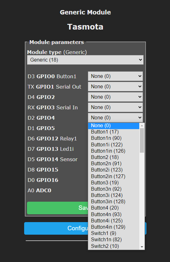 .
.
There are many different options to choose from, some more general and others more specialised:
 .
.
For example, Relay1 here is the first relay and Relay2 is the second relay. There are also options such as Relay1i and Relay2i, which are simply inverted outputs for the same relays. We can define for ourselves whether a high state means that the relay is switched on or off.
Tasmota - relay and LED operation .
For a known device, you can simply use Tasmota's ready-made template (template). Here, however, I did not have this option. The SC3-01 from the topic does not yet have a template, so we have to configure it ourselves.
First you need to determine on which ESP pins the relay (or relays) are connected. I managed to do this experimentally - I simply set the pins one by one in Relay mode and checked which one works. Setting:
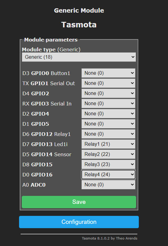 .
.
Testing:
 .
.
Eventually I discovered that for the SC3-01, we have two pins available as outputs - GPIO15 and GPIO16. One is the relay and the other is the LED (which can be controlled independently of the relay, although the relay still has its own separate LED):
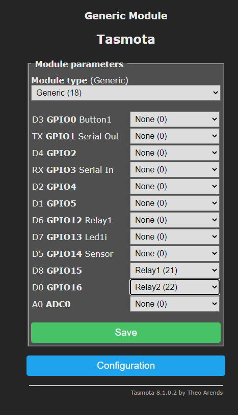 .
.
 .
.
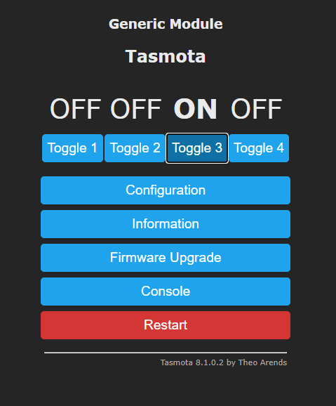
I show the result in the video:
Everything works, we can already control the relay and the LED, the operation of the touch button remains.
Tasmota - touch button operation .
To determine the pin on which the button is connected I used the same method as for the relay. I simply set the pins sequentially through the web panel and checked that the button responded:
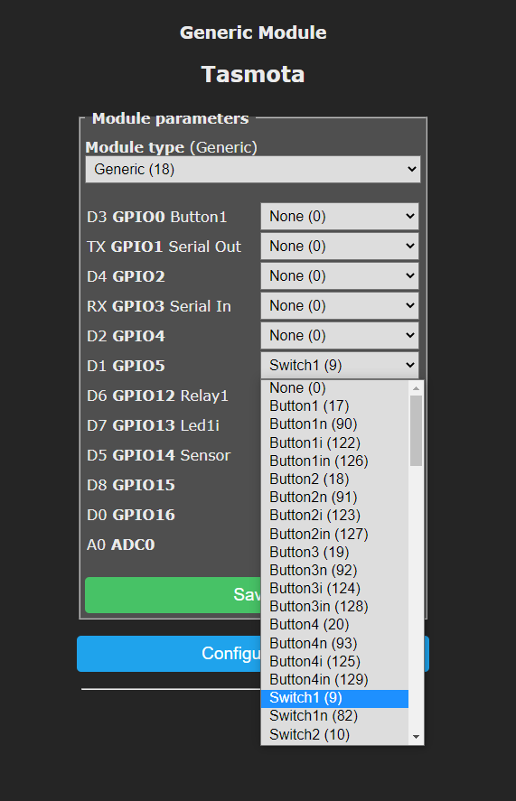 .
.
I determined that the touch button was on the GPIO5 pin:
 .
.
However, the device was not working as it should:
The lamp only lit up when the button was pressed. And it should be different - pressing the button should toggle the lamp state. This is because I used Switch1 instead of Button1, or actually Button1i (Button1 would result in the bulb state changing when you take your finger off the button, whereas Button1i results in the bulb state changing when the button is pressed)
After swapping this Switch setting to Button, the switch began to function fully correctly and as expected. .
Batch upload via USB<->UART converter .
The whole topic is devoted to uploading the batch via WiFi, but it is still worth knowing about an alternative option.
It may be needed in three cases:
- if we break something ourselves (we upload via WiFi e.g. an inappropriate batch or one that does not allow updates)
- if, after purchase, we configure the device to work with the application and the manufacturer's cloud (it happens that the manufacturer will then itself make a firmware update which spoils the tuya-convert)
- if the purchased device is simply not supported by tuya-convert
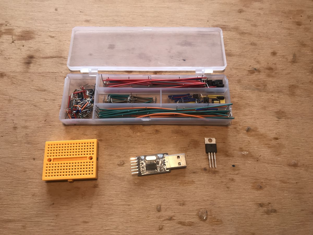
The method described here is based on a simple USB to UART converter, a 3.3V LDO regulator, a contact board and some wires and one connector. .
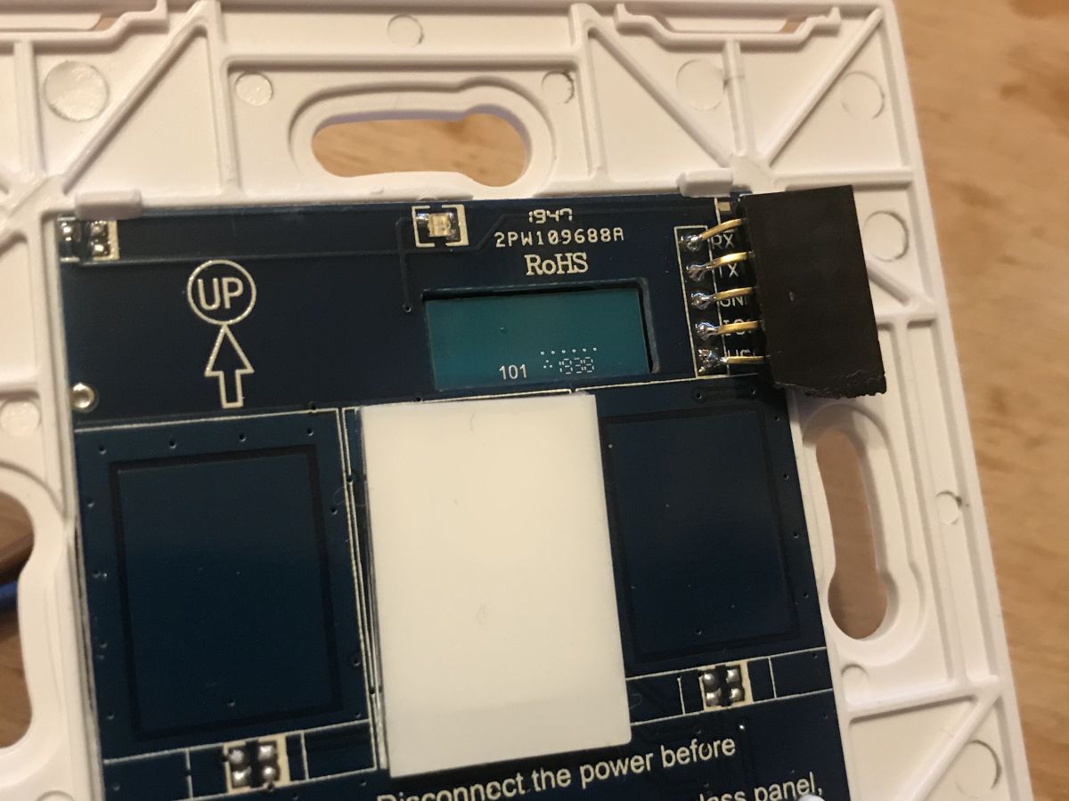
To start, we add a goldpin connector to the pins already brought out on the front board:
 .
.
These pins are, in sequence:
- GND (ground)
- VCC (3.3V)
- RX (it is connected in the case of this switch to TX from TYWE3S, so we connect RX from the adapter to it)
- TX (this pin is connected to the RX from TYWE3S, so it is connected to the TX from the adapter)
- IO0 (pin to enable programming mode)
The RST pin is not brought out here, but it is not needed. We will simply replace the RESET pin with a power cut, but more on that later.
It is necessary to connect to this connector conveniently somehow.
We can't just add goldpins here, because we wouldn't be able to put the front cover on that way. We have to solve this differently. The connector can be soldered on a slant:
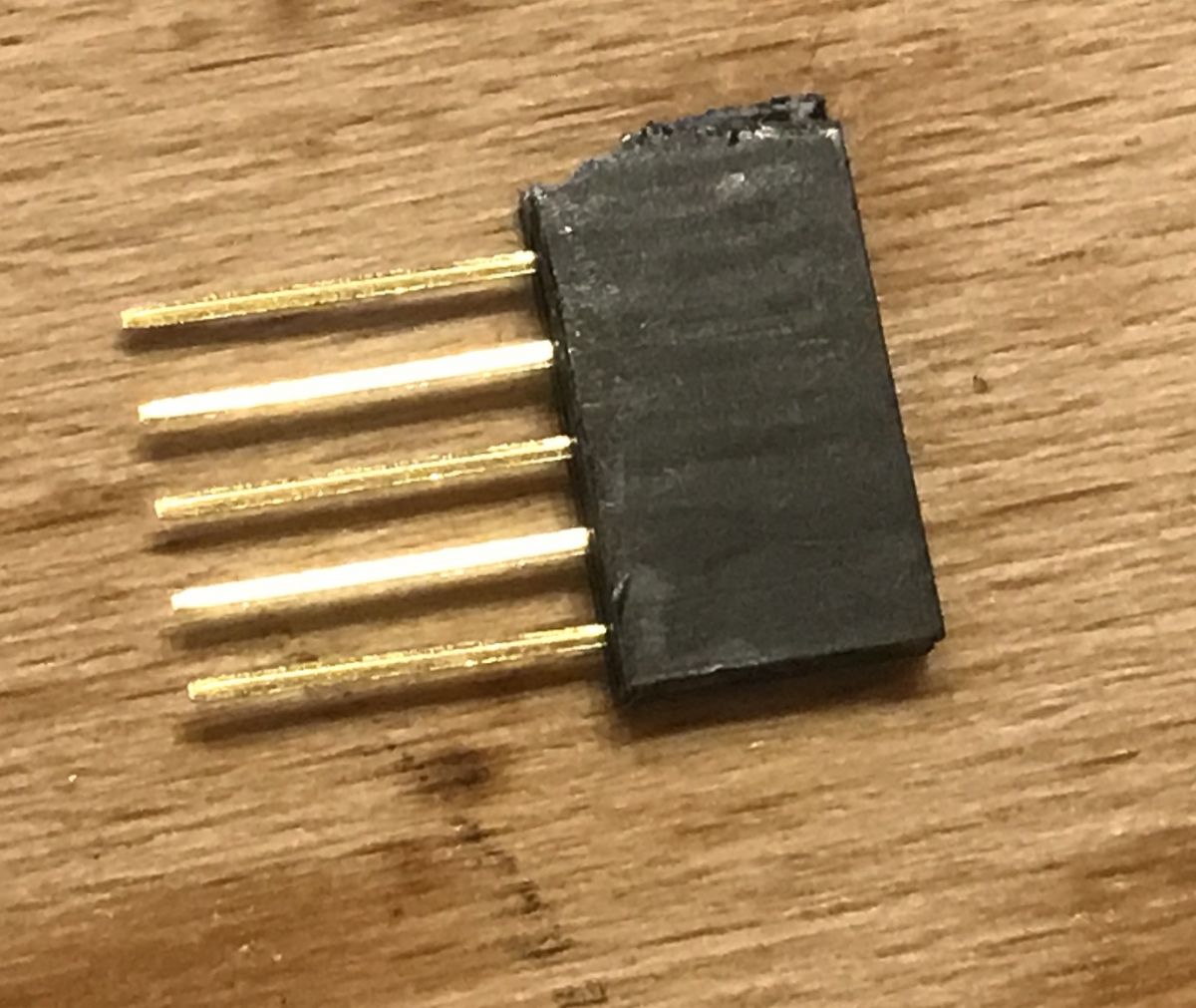 .
.
The connector soldered in this way fits under the cover:
 .
.
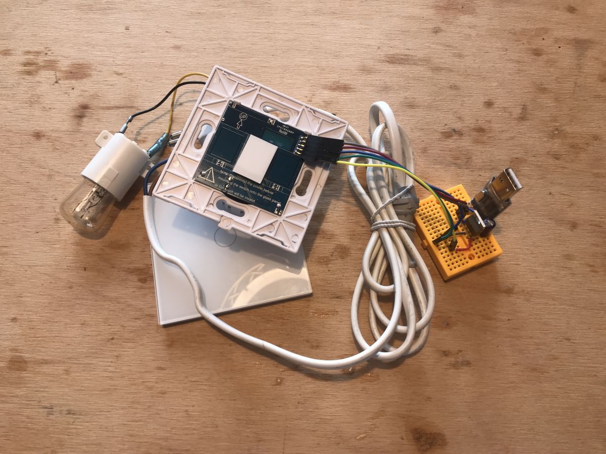
Already with wires from the contact plates:
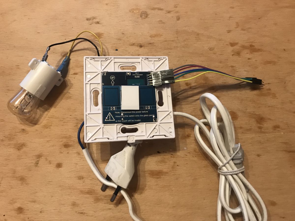 .
.
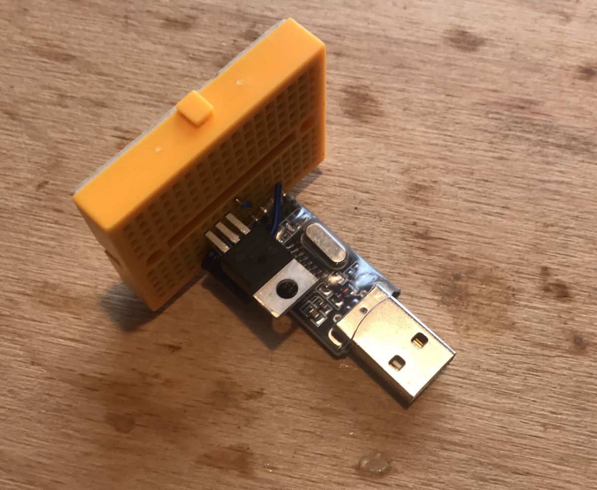
Next you need to connect the 3.3V power supply and the USB<->UART converter. Here I used the cheapest USB TO TTL HW-597:
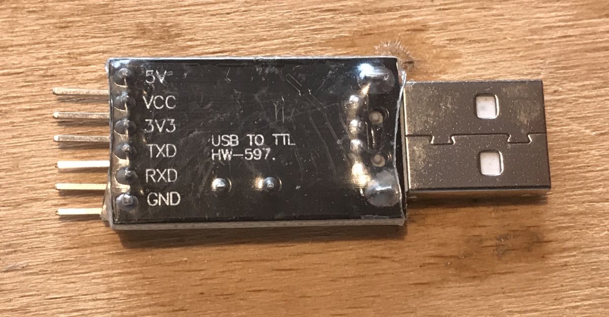 .
.
I obtained the 3.3V from 5V via a TC1264 3.3V LDO regulator (but you can use any; just don't connect the TYWE3S directly to 5V from USB, it will damage it):
 .
.
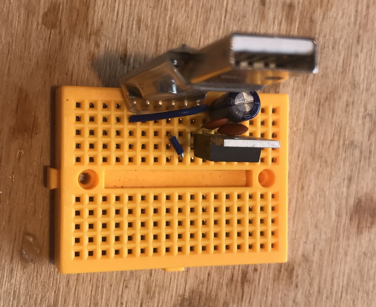
I connected everything on the contact board. Additionally, I shorted the 3.3V and VDD pins on the UART converter (this means that we select the logic level at 3.3V). I connected the 5V pin from the USB UART converter to the 3.3V LDO (because 3.3V directly from the converter does not have enough current capacity). For the LDO regulator, I also connected 100nF capacitors to the input and output:
 .
.
In this way I prepared myself a kit to upload the batch to TYWE3S:
 .
.
Wiring diagram:
 .
.
On the computer side, I used the esptool.py script that I installed with the ESP8266 support package for the Arduino IDE.
https://github.com/esp8266/Arduino
I installed the ESP8266 support in the Arduino IDE via the Boards Manager.
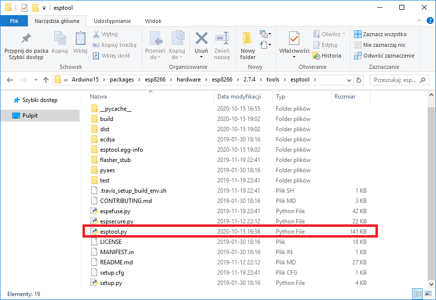
After installation, esptool.py appeared in this location with me (but you guys probably have a different username):
C:AppDataLocalArduino15.7.4 esptool .
 .
.
Esptool.py is used from the command line. We open the CMD, navigate to its location (command cd C:AppDataLocalArduino15packagesesp8266hardware2.7.4 esptools ) and then we can use it:
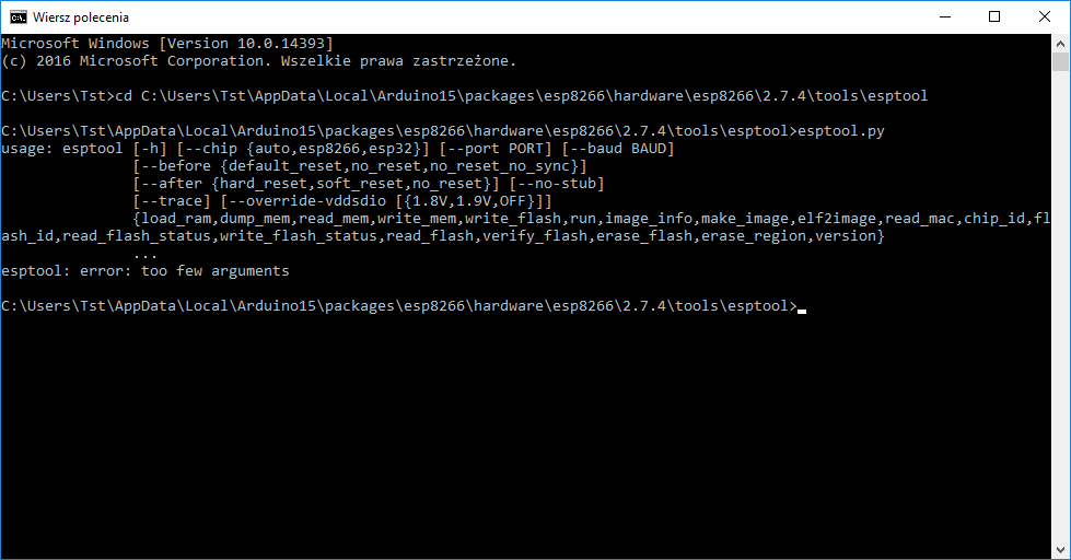 .
.
Now it is time to check if our programmer is able to communicate with the TYWE3S. .
The command esptool.py read_id reads information about the connected chip.
The procedure for executing the command is simple:
- we disconnect our DIY programmer from the USB (and from the power supply)
- first short-circuit GPIO0 to ground (it is on the programming output)
- then connect the programmer to USB (only then does it get power)
- disconnect GPIO0 from GND (you may have to connect it to 3.3V via pull-up resistor)
- only then do we enter the command on the computer
The result is shown below:
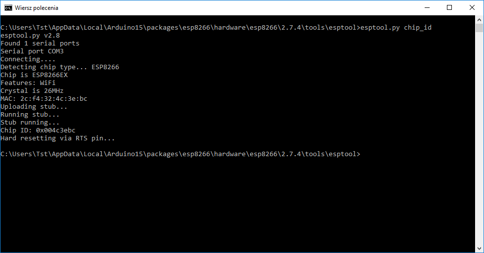 .
.
Communication with TYWE3S is working. The chip has been correctly recognised as an ESP8266. Its MAC 2c:f4:32:4c:3e:bc also matches.
Now I will still demonstrate how to upload the Tasmota firmware to it via this (I don't have to do it, but you will find it useful just in case).
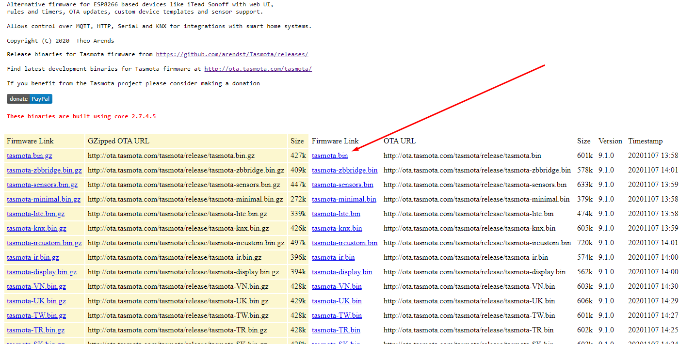
We download the latest version from:
http://ota.tasmota.com/tasmota/release/
 .
.
We upload it loosely for convenience alongside esptool.py:
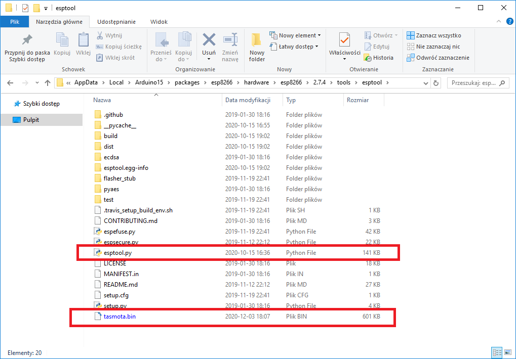 .
.
And we do the ESP8266 programming, the procedure as I described for chip_id, but with the command esptool.py write_flash 0x0 tasmota.bin .
Result:
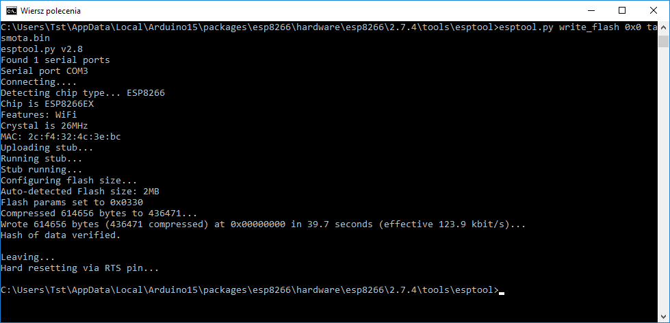 .
.
Unplug the power supply, plug it in again and thus we have a clean tasmota firmware uploaded again:
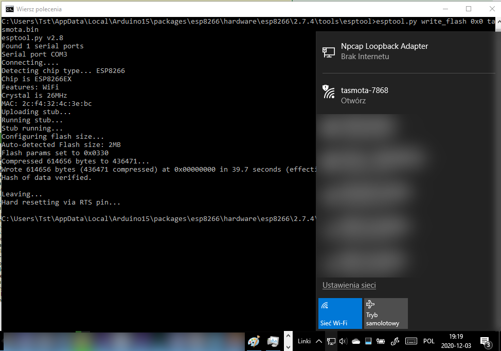 .
.
And we're back to square one, we can now connect to the tasmota-xxxx network, set its information about our WiFi, etc. etc....
What can we do next? .
A smart device with its own batch is, of course, only the starting point. Now you can do a lot more, among other things:
- set it a hostname (e.g. by assigning a hostname to its mac address on the router) or a fixed IP
- add it to the Tasmota-Control Android app
- organise a better way of controlling it via MQTT (topic to be described), e.g. put up Home Assistant and hook it up there
The configuration of more IoT devices together with Home Assistant will be described in the forum soon.
The RF433 communication module .
Unfortunately I have not had the opportunity to test the RF433 remote control with this switch. I don't have any such remote control at the moment, but will make up for it soon.
However, I have noticed an interesting phenomenon which occurs even after the batch is completely removed from the TYWE3S (ESP), namely a prolonged touch press results first in a single and then in a double buzzer signal:
This is part of the process of pairing the 433MHz remote control with the switch. When you have a remote, you press a button on it after the beep and the remote pairs with the circuit.
Multiple remote controls can be paired with a given device.
The interesting thing is that this is completely independent of the firmware from TYWE3S. .
I have also sketched the connections from the 433 chip:
 .
.
(in green marked path to GPIO5)
At this point, in my opinion, it works like this: the chip from 433 has only one pin for communication, this pin is also connected to the touch button controller and to the GPIO5 TYWE3S pin. Normally this pin has a pull-up and is in the high state. A short press of the button is simply ignored by the circuit from 433. A long press of the button (long short to ground) is received by the 433 as a pairing signal with the 433MHz remote control. In addition, when the remote control gives a signal for the circuit from the 433, the 433 itself short-circuits this pin to ground, simulating a button press. That is, the ESP "doesn't even know" that there is a circuit from the 433. A simple and ingenious solution.
Diagnosis of problems Diagnosis of problems.
The process of uploading a batch via tuya-convert is very simple, but can sometimes cause problems for beginners. Here I will give a list of tips-questions to check when something is wrong.
- are you using an up-to-date version of Ubuntu (I had a problem with Python on an older version)?
- is the WiFi dongle connected to our virtual machine (in the VMware settings, if we use that) and not to the main computer?
- does the command lsusb see our WiFi dongle?
- does the command ifconfig see the network interface from the WiFi dongle?
- does the WiFi dongle we bought support AP mode (is it able to create its own WiFi network)?
- do we run commands in administrator mode? ( sudo )
- is the device close enough to the WiFi dongle?
- whether the name of the WiFi interface is the same as in the tuya-convert configuration (it is also worth trying to set this name to wlan0)
- does our Smart Home device actually have a module with ESP from Tuya in it?
The details of how to use the commands listed above are in the body of the topic.
Materials from the web .
I include links to them here as a supplement to the article. They are, of course, in English.
Tuya-convert repository:
https://github.com/ct-Open-Source/tuya-convert
Tasmota homepage:
https://tasmota.github.io/docs/
Tasmota templates page:
https://templates.blakadder.com/
TYWE3S programming information:
https://tasmota.github.io/docs/devices/TYWE3S/
TYWE3S programming "helper" 3D printed:
https://www.thingiverse.com/thing:3231225
Uploading Tasmota via Esptool (but I did it a bit differently, the method from the link was not tested!):
https://tasmota.github.io/docs/Esptool/
It's also worth knowing that there is also such a thing as tuyapi, an API that allows you to use Tuya devices without changing their firmware:
https://github.com/codetheweb/tuyapi
For the next part For the next part For the next part.
I have already covered ESP-related IoT devices in at least a few topics. For a change, I intend to cover Zigbee soon, more specifically the Aqara series:
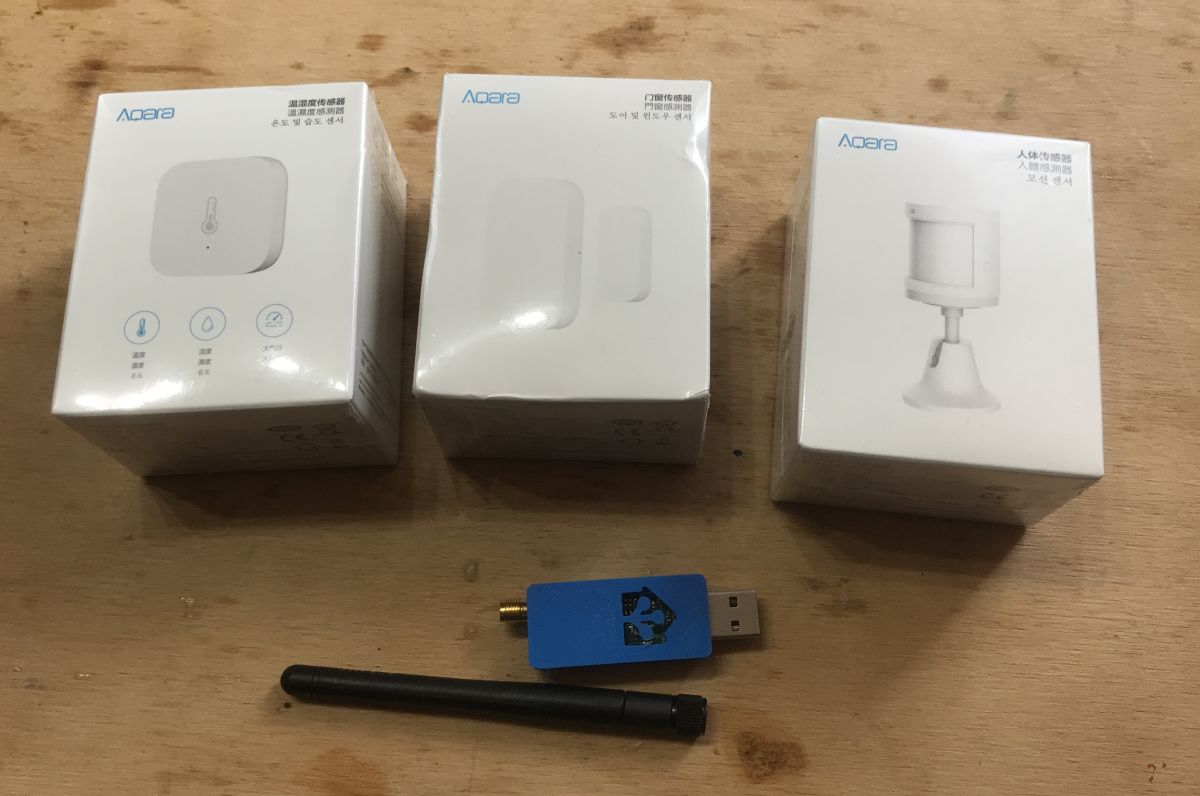 .
.
I will try to use it with the Home Assistant.
Summary .
The SC3-01 SmartLife switch is based on the Tuya TYWE3S module with ESP8266. It can be easily programmed by connecting with wires (via UART) to the lead-out port on the PCB, but even easier to access via tuya-convert. This does not require any soldering at all, but you do need to have this WiFi card on USB supporting Access Point mode. Both methods have their pros and cons, but ultimately produce the same result.
With tuya-convert you can upload any batch to the smart device, but you have to remember that the uploaded batch overwrites what is inside, so after uploading you can't use tuya-convert again and you can cut yourself off from the device (then you have to open the casing and program via UART). Unless the uploaded batch supports the update via WiFi (OTA, Over The Air), then there is no problem.
In addition, the SC3-01 SmartLife switch also supports a 433MHz remote control, which can be conveniently paired with it, and this works surprisingly independently of the batch from the ESP. So that's an extra plus. Whether you upload Tasmota, or Domoticz, or your own batch, the 433MHz remote will still work.

p.kaczmarek2 wrote 14756 posts with
rating 12883 , helped 659 times.
Been with us since 2014 year.
Comments
I have not encountered more comprehensive material on uploading and configuring tasmota ;) Bravo. I will mention that tuya-convert will not always work and with newer devices already tuya uploads fixes.... [Read more]
Does the article tell us what uploading firmware does? Was it written to show the possibility of programming over Wi-Fi? Not to pick on you, but did you change anything by uploading the firmware? Well,... [Read more]
Apparently it can still be done differently, without the need to solder the cables to the board itself. There is such an overlay for TYWE3S available for download on the Thingiverse: https://obrazki.elektroda.pl/1650647600_1611154594_thumb.jpg... [Read more]
. only when esp in such a module. Here it will no longer help: https://obrazki.elektroda.pl/6231235600_1611155384_thumb.jpg . [Read more]
Why do you think Switch is better than Button? Tasmota's documentation (as well as the naming itself) suggests that: . In my opinion, in the case of the device in the topic, we are closer to a button... [Read more]
Thanks for describing the product in detail. I personally use a Sonoff to which I have the light connected. I have Tasmota preloaded (I uploaded it over a year ago). Please tell me how it is with Tasmota... [Read more]
because having a switch you can use SwitchMode, and that gives you a lot more options. There are many more switch modes, when you press, when you let go, hold, etc. etc. Link . Button itself also seems... [Read more]
Just to add regarding Tuya-convert. You should check 3x the correctness of the wifi ssid and password immediately after using the Tuya-convert script. The error will make your device unbootable - maybe... [Read more]
. Are you writing about tasmota ? Tasmota has something like "Fast Power Cycle Device Recovery" reset by briefly turning the device off 7 times and by default this mode is active. [Read more]
And I didn't know that. There is a relevant warning on the script author's website https://github.com/ct-Open-Source/tuya-convert . I took this warning seriously and have been using the script for over... [Read more]
Hello. For those looking for switches, I will share my first test purchase of the BONDA brand. I spent a long time looking for how to configure it after uploading tasmota and after two days of struggling... [Read more]
Respect for a long and comprehensive article. It has been a long time since I read with such interest. [Read more]
How did you manage to enable AP mode on this card ? I have the same card and Ubuntu sees under lsusb as: Bus 003 Device 005: ID 2357:010c TP-Link TL-WN722N v2/v3 [Realtek RTL8188EUS]. In contrast,... [Read more]
Hello, Is it necessary to have an external wi fi card (ala flash drive), I started to upload tasmota via VMvare but I don't have a wifi card. Is it possible to complete the flashing without a wifi card... [Read more]