A PIC18F67J60-based Ethernet relay driver with four relays, temperature sensing, alarm clock features, USB configuration, an independent web panel, and a PLA 3D-printed case.
It uses Tasmota-style HTTP endpoints for Home Assistant and Tasmota Control compatibility, plus MCP2221 USB-UART, I2C EEPROMs, and TC74 temperature sensors.
The PCB measures 10 cm by 7.6 cm and includes six 24AA256 EEPROMs, a MIC2940 3.3V regulator, and SRD-05VDC-SL-C relays.
The board runs both local control and HA automations, but httas needed manual fixes for newer Home Assistant, and the first board had power-noise issues.
Summary generated by AI based on the discussion content.
Here I am going to present my Home Assistant compatible network relay driver, based on Tasmota HTTP protocol. The controller is using the PIC18F67J60 8-bit MCU with integrated RJ45 cable networking and features relays control, temperature reading, alarm clock, buttons, independent web panel and wide configuration options.
Introduction The project was created to better understand the operation of IoT and HA.
System features:
- Compatibility with Home Assistant and the Tasmota Control app for Android (thanks to the use of Tasmota HTTP)
- web panel independent from Home Assistant (but you can also control everything via Home Assistant)
- control of 4 relays via the panel or HA
- possibility to add an expansion card with additional 10 relays (or more)
- alarm clock / buzzer functionality
- temperature reading from thermometers on I2C (along with graphs on your own website and sending them to the Home Assistant)
- possibility to configure via USB
- synchronization with time from the Internet via NTP
- own EEPROM memory (useful when we want to use the controller without pairing it with Home Assistant)
- static IP and DHCP support
PCB board design Most of the elements used in the project I already had and knew from previous attempts.
The heart of the system is the 'Ethernet' microcontroller PIC18F67J60 which basically has everything needed to implement such communication (it's like ENC28J60 + microcontroller in one).
Of course, a socket for an RJ45 connector with an integrated signal transformer is connected to it, the so-called 'magjack', in this case I used JXD1-0008NL .
The power supply of the system is connected via a USB type C plug. PIC is powered from 3.3V, so there is also a 3.3V LDO regulator on the board - MIC2940 .
The USB connector on the board also has a communication function - it is connected to it MCP2221 , USB UART converter, which in turn is connected to the UART from the PIC.
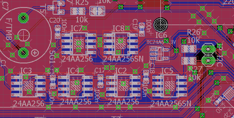
In addition, I put 6 memories in the free space on the board 24AA256 all on one I2C bus. I have some of these memories, so I chose them instead of the SD card.
There is also a tiny thermometer mounted on the I2C bus TC74 (more for testing and because there was 'room', because the temperature read by him will be slightly overestimated by the heating of the system).
PIC's IO pins lead to 4 independent buttons, 4 LEDs and 4 relays controlled by transistors BC847 .
The relays themselves are SRD-05VDC-SL-C .
There is also a buzzer inside, so that it can also be used for example as an alarm clock.
The board also has a green 'standby' LED and a RESET button.
RESET can also be triggered remotely via MCP2221 (via its GPIO). A separate transistor and a jumper 'CDC_RST' are used for this. This is for possible programming via the UART bootloader.
The board also has additional pins and I2C in order to enable its development by making a simple overlay with additional relays.
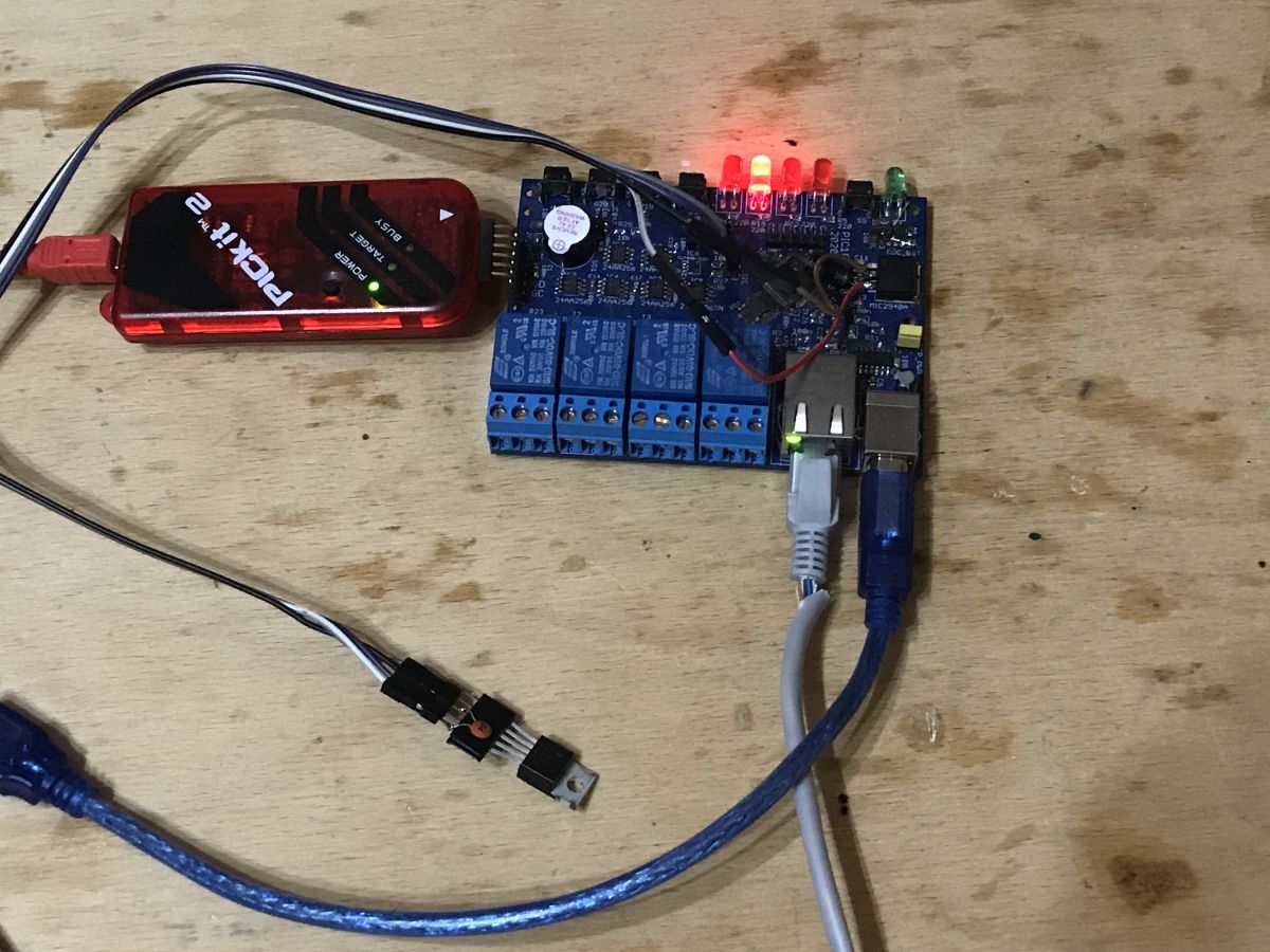
There is an ICSP connector on the side of the board so that it can also be easily programmed with the PICKIT.
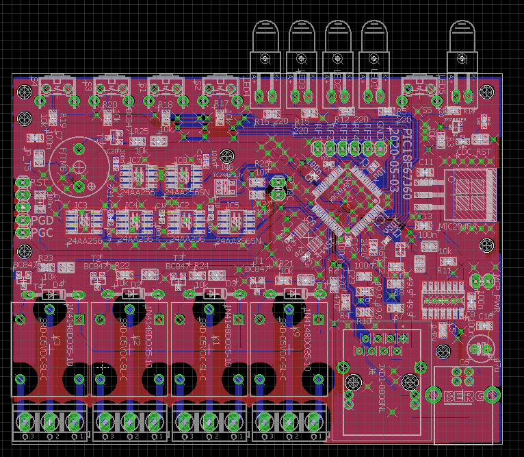
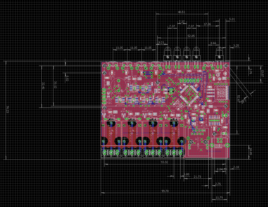
The design was done in Eagle, the dimensions are 10cm by 7.6cm. The 10cm limit is dictated by the prices in the tile mill (tiles up to 100mm by 100mm are the cheapest).
PCB Design:
(As for those strange jumpers on the board - they are given in case I want to easily connect, for example, a relay to another pin. The project was just done a bit at nights / weekends and I was not sure if everything was ok, I wanted to leave a gate for myself for easy modification)
Diagram:
PIC18F67Re...em.png.zip (106.92 kB)You must be logged in to download this attachment. Eagle Source Files:
PIC18F67Re...-eagle.zip (126.24 kB)You must be logged in to download this attachment. Gerberas that I sent to the tiler:
PIC18F67Re...erbers.zip (344.56 kB)You must be logged in to download this attachment.
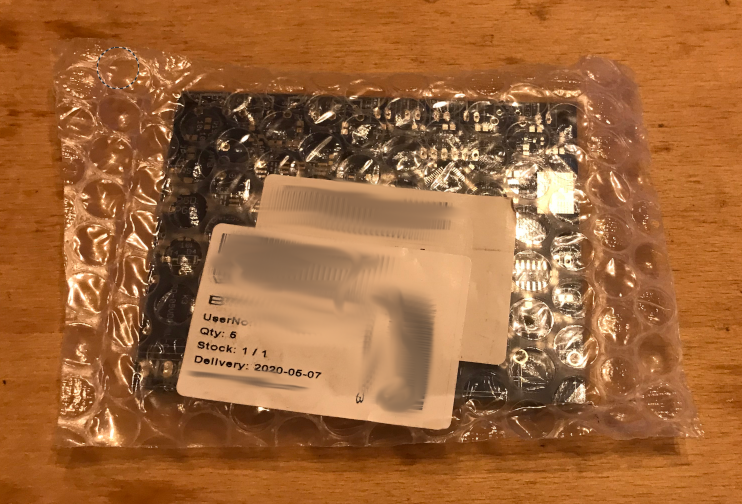
Soldering the PCB I ordered the PCB itself in a tiling plant. I ordered 5 pieces, which is the cheapest option:
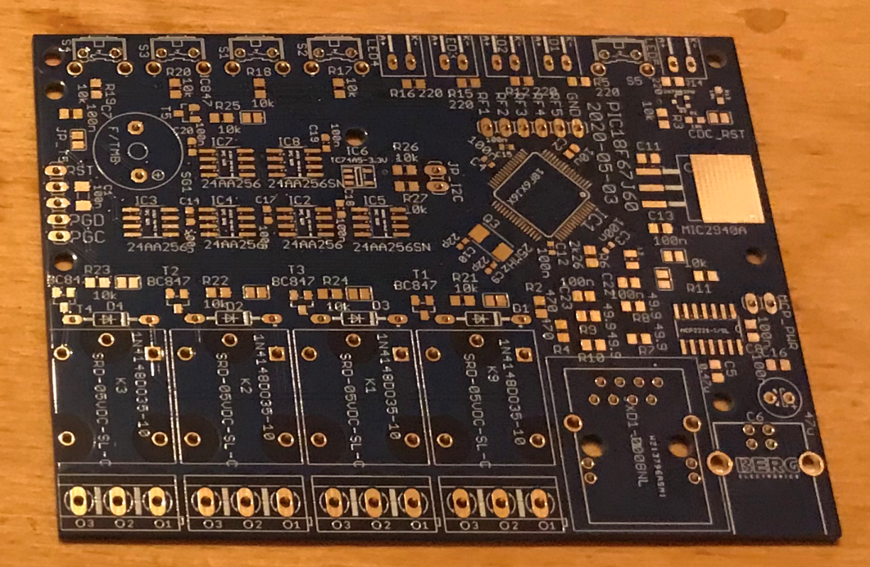
Blank PCB:
Beginning of soldering:
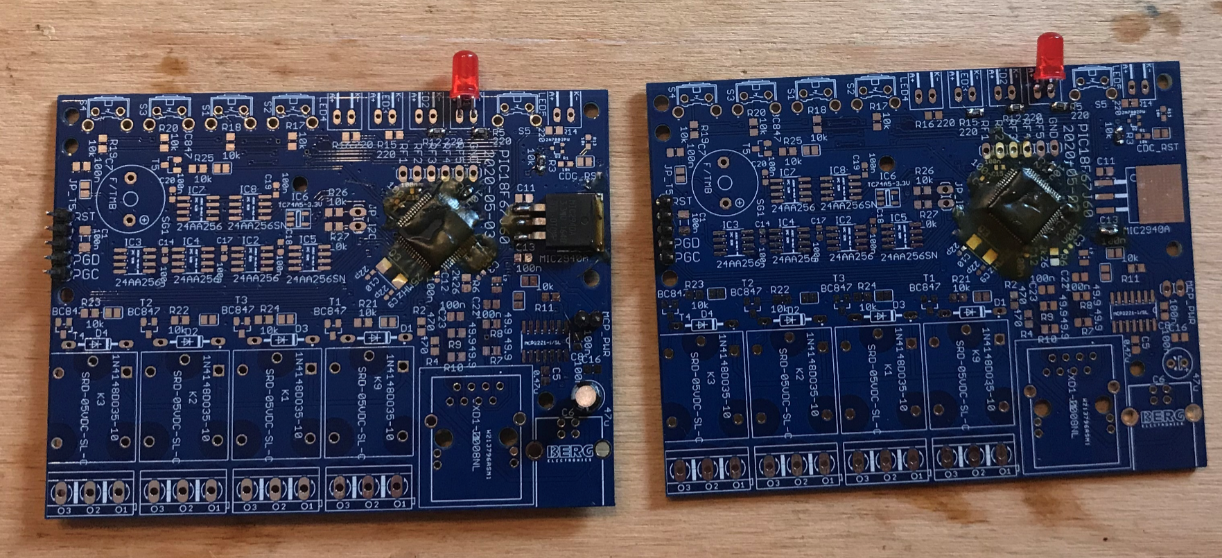
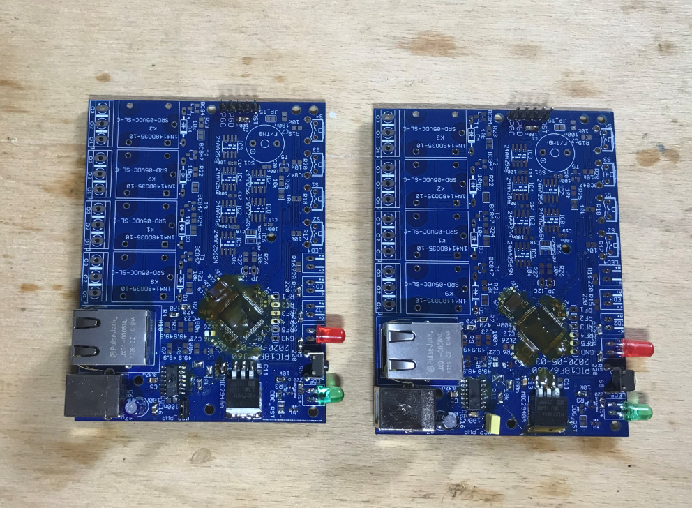
First functional chip - PIC, resonator, power supply, MCP2221, programming connector. At this stage, I have already checked if the PIC is working (I solder with a cheap soldering iron and I can see poorly, so I want to know at an early stage if everything is OK):
Ready Ethernet systems (communication is also already working), first relay:
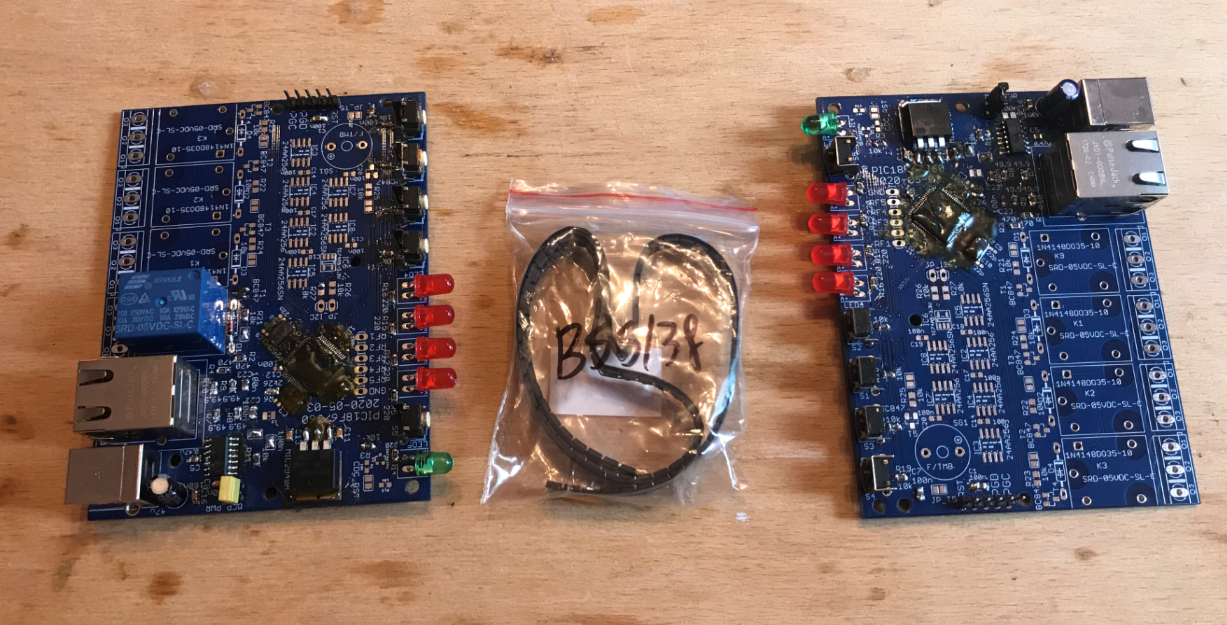
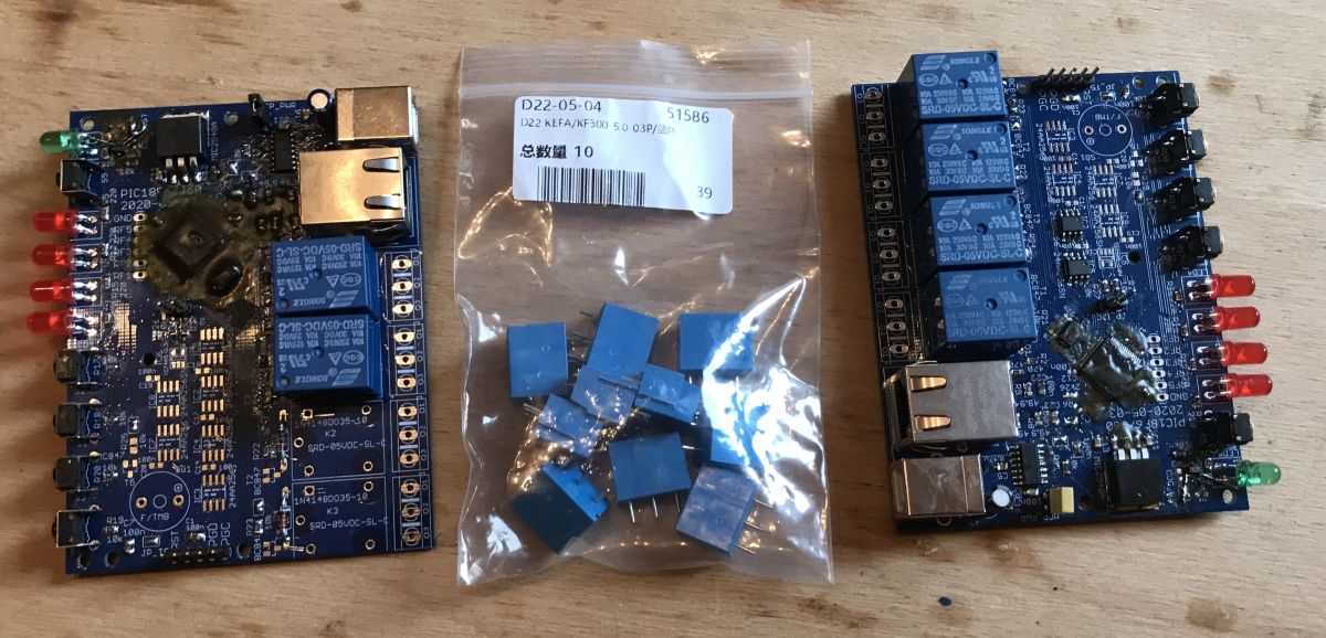
Continuation of soldering (after a few months of break), delivery of KF300 3-pin connectors:
Already with a buzzer and an additional TC74A thermometer on a longer cable (one TC74A is in the SMD housing on the board, the other is in the TO220 housing on the cable):
Almost ready version, partially purged of flux:
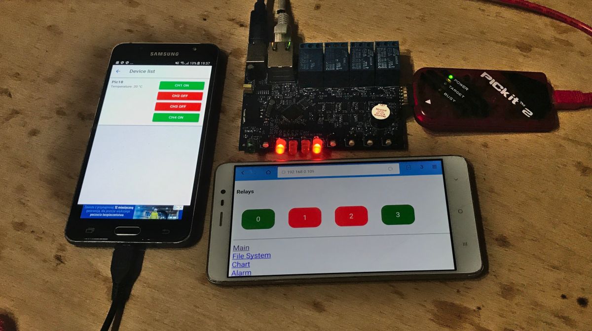
Ready version, one phone with Tasmota Control, the other with WWW page from PIC:
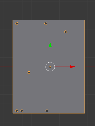
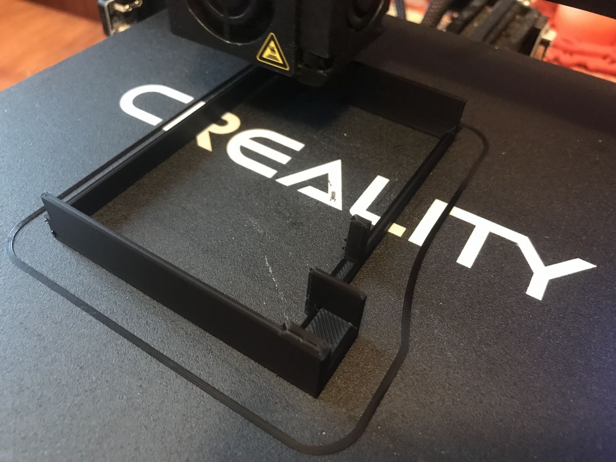
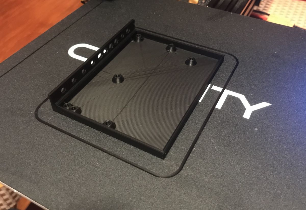
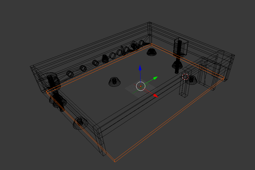
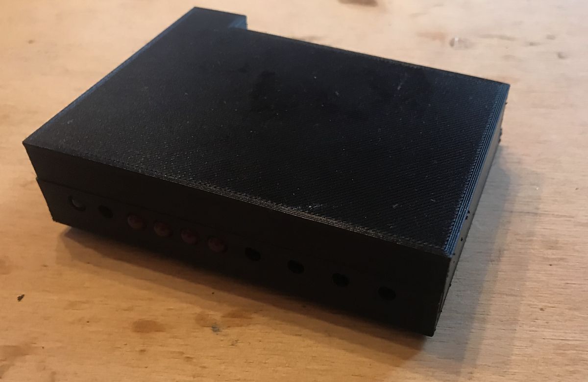
3d-printed case I designed the housing in Blender and printed it from PLA filament on my Ender 3 PRO printer.
At the beginning, I have drawn up the more precise dimensions of the plate:
I transferred them to Blender.
First prints, try-on:
Second version:
Try on, topless version:
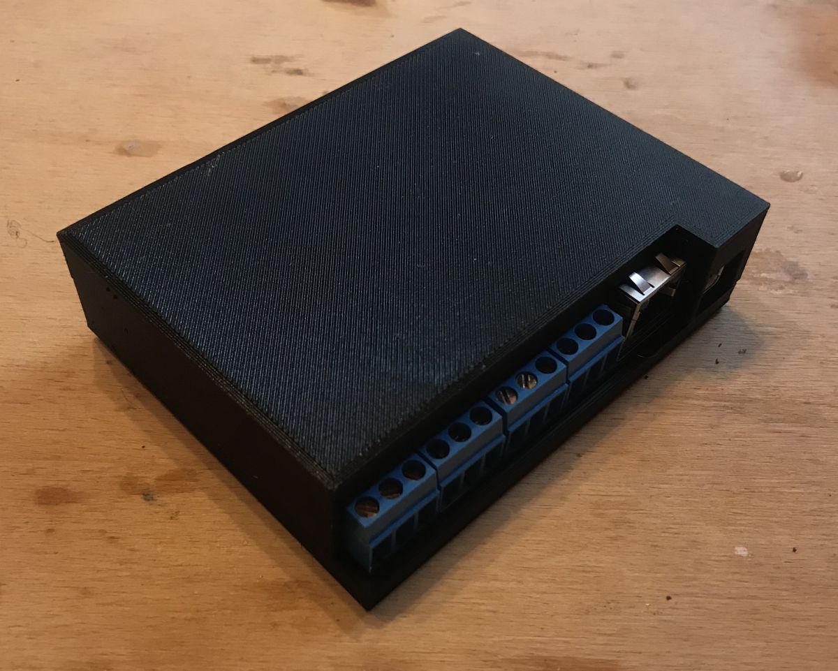
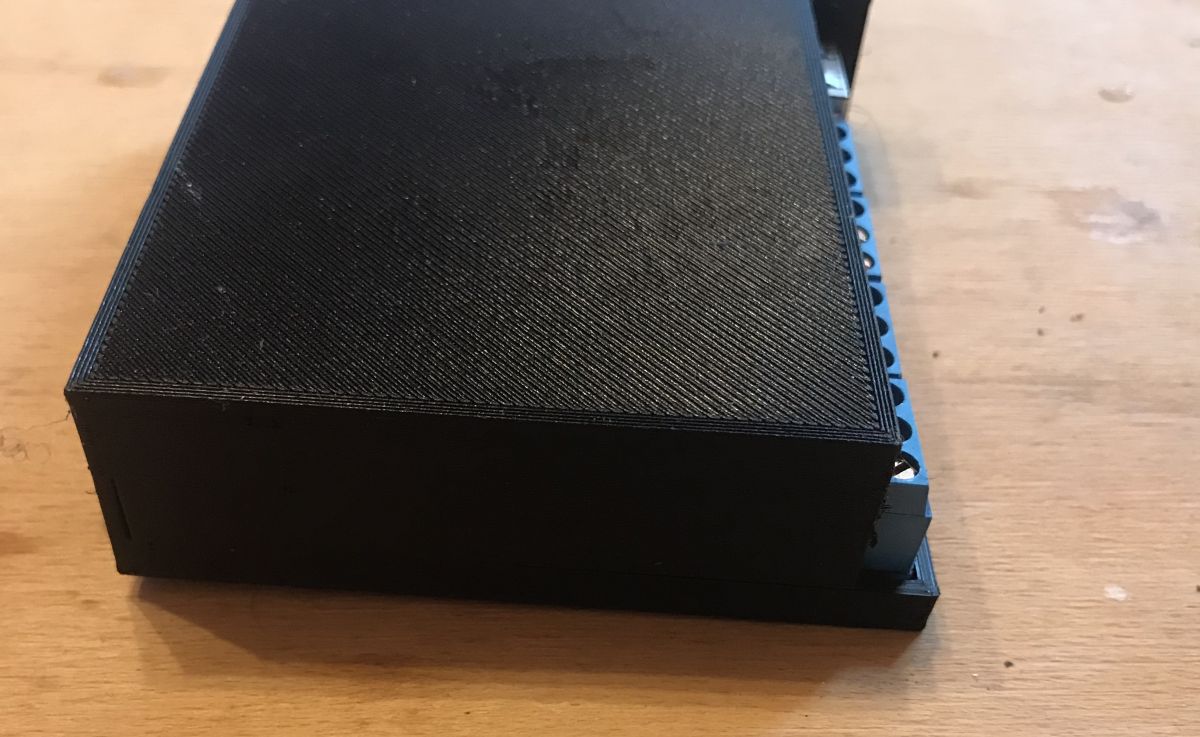
Final Project:
Final effect:
The housing, of course, requires additional printing of buttons that protrude from the housing and touch the tactile switches.
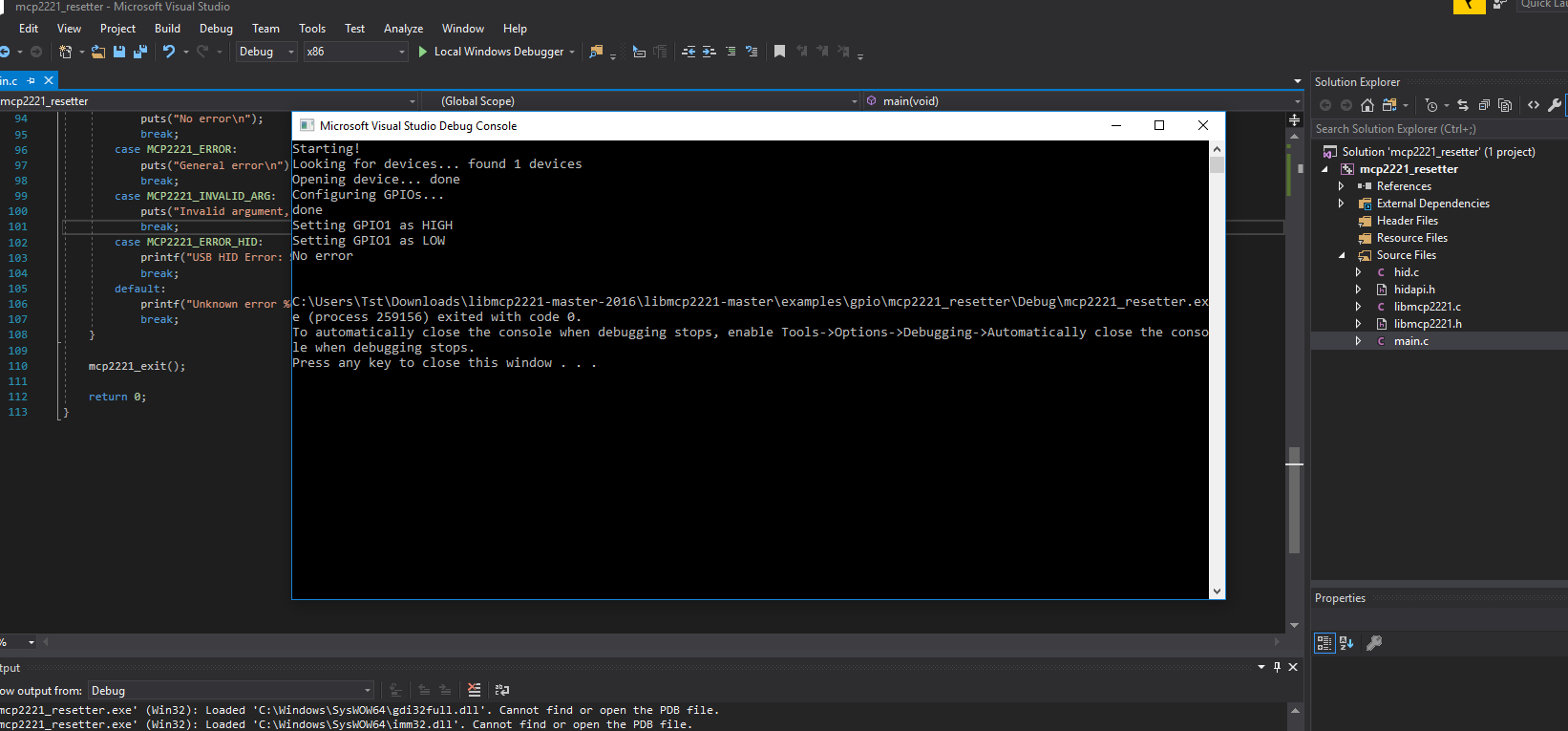
PC program for resetting the chip via USB This program was created because initially I planned to develop a USB bootloader (or rather UART), but in the end I decided that such a bootloader is unnecessary because I have ICSP on the housing anyway.
Nevertheless, I will describe it here.
This program uses an additional digital GPIO from the MCP2221 to short the MCLR pin from the PIC to ground.
The program uses two libraries:
- MCP2221 HID Library- Author: Zak Kemble, contact(_at_)zakkemble.co.uk
- HIDAPI - Multi-Platform library for communication with HID devices. - Alan Ott Signal 11 Software
I put it all in a single, easy to compile Visual Studio project - no need to download any dependencies, attachment below:
mcp2221_re...210306.zip (25.83 kB)You must be logged in to download this attachment. Screenshot of the activity:
Code:
Code: C / C++
Log in, to see the code
Let me just add that there is a potential trap for beginners here. The MCP2221 allows you to save the configuration in its memory and remembers it after disconnecting the power supply. If we configure it so that by default my chip reset pin is high, then save this configuration with mcp2221_saveGPIOConf (myDev, & gpioConf); then we will not run my board normally in any way, because the PIC will still be in the RESET state.
Time from the Internet via NTP The program on the PIC18F67J60 regularly downloads time from the Internet via the NTP protocol. Of course, the time is also counted locally, but there is no watch quartz resonator on the board and in the long run, without synchronization with the Internet, large distortions would quickly arise in the hour shown.
Downloading time from the Internet is limited to sending one packet in connectionless mode (UDP) and receiving a response to it. The PIC can handle this and can handle both UDP and TCP (as an HTTP server) at the same time.
Package structure:
Code: C / C++
Log in, to see the code
The send / receive details are in the code.
Final firmware version The code is written in Mikro C, but it doesn't really matter, because the functions are separated so that it can be easily transferred to another compiler or platform. The whole thing is divided into files:
file name
Short description
interrupt.c
interrupt implementation, support for timer counting time, circular buffer from UART, function reading line from UART (for command line)
memory.c
memory support via I2C (both single-byte write and page-write are supported, but functions from page do not support multi page write, details in memory directory note)
settings.c
saving and reading IP settings and more from memory
files.c
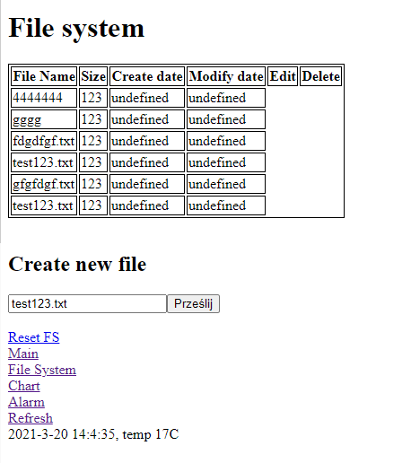
unfinished filesystem that was supposed to be on EEPROM memories, listing files, creating them, deleting them
tc74.c
TC74 support via I2C (temperature reading as an integer)
relays_and_leds.c
Basic port support in digital output mode is used to control relays and LEDs
helpers.c
auxiliary functions, e.g. checksum function, it is used, among others for configuration verification from EEPROM memory
main.c
main file, packet receipt and main loop, plus UART command line
alarm c
alarm clock file, time parsing, alarm settings, reading and writing time from EEPROM memory
e.g. c
support for downloading time from the Internet via NTP (sending a packet via UDP and receiving a response)
main.h
a collective header for the entire project
I wrote the code with the assumption that he would not encounter a malicious user trying to make a buffer overflow, for example. It is possible that I will improve it soon.
Final download version:
PIC18F67J6...210320.zip (708.86 kB)You must be logged in to download this attachment.
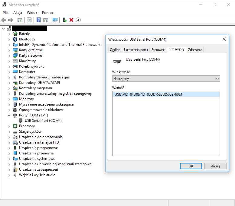
Freedom of configuration via USB without the need for programming The USB UART converter MCP2221 provides the ability to configure everything without access to the LAN network and without a programmer.
After connecting to the computer with a USB cable, we get a virtual COM port:
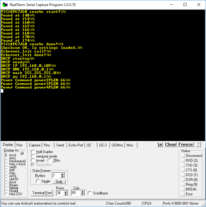
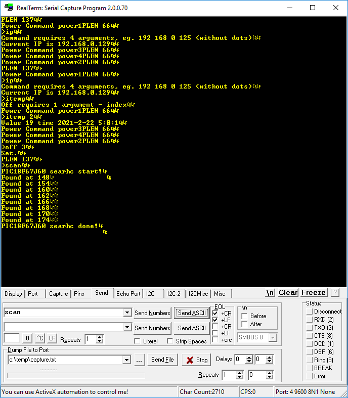
Then it is enough to run only a UART terminal, e.g. RealTerm and you can receive logs from the device:
You can also send commands. Each command ends with CR LF characters:
Below is a shortened list of commands:
Command
Arguments
Short description
date / time / now
lack
displays the current time (regularly synchronized with the Internet via NTP)
temp
lack
displays the latest temperature measurements
state
lack
displays the status of relays
toggle
index
toggles the state of a given relay
off
index
turns off the relay
he
index
turns on a given relay
dhcp
0 or 1
enables or disables DHCP
ip
IP address as ABCD
sets static IP
ip
lack
displays the current IP
mask
mask as ABCD
sets the mask
dns
IP as ABCD
sets the DNS server IP
gw
IP as ABCD
sets the default gateway IP
mother
MAC as ABCDEF
sets the physical MAC address of the device
save
lack
saves settings in EEPROM memory
scan
lack
performs a scan of devices on the I2C bus and writes out their addresses
buzz
lack
forces a buzzer to sound for half a second
get alarm
lack
displays information about the set alarm (alarm clock)
EEPROM memory and I2C bus There are 6 EEPROM chips on the board on one I2C bus.
The program automatically scans the I2C bus at system startup and lists the devices found. The memory handling code in my memory.c file supports writing and reading from these memories in two modes: single byte and full page (page read / page write). One of the memories is used to store the network configuration, alarm clock settings and the history of readings from sensors (date / time + measurement result).
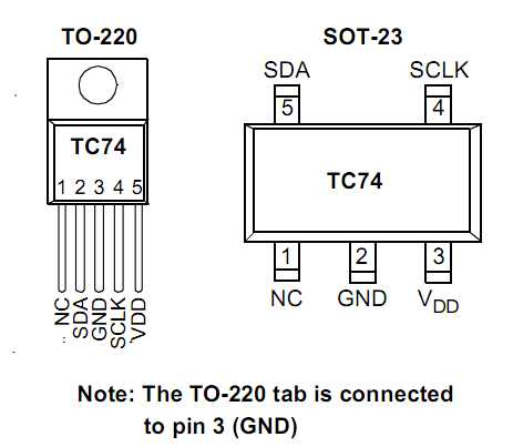
Temperature sensors on I2C The I2C bus allows you to connect a large number of devices using this protocol, including temperature sensors. In the project I used the TC74 sensor:
TC74 is available in versions with different addresses, which allows you to place many such sensors on one I2C line at the same time:
There is one TC74 in an SMD housing on the board, but it is more for testing, because heating inside the housing would slightly distort the results. But on I2C you can also connect additional sensors, even on quite long cables (depending, among others, on the I2C clock). Here one connected:
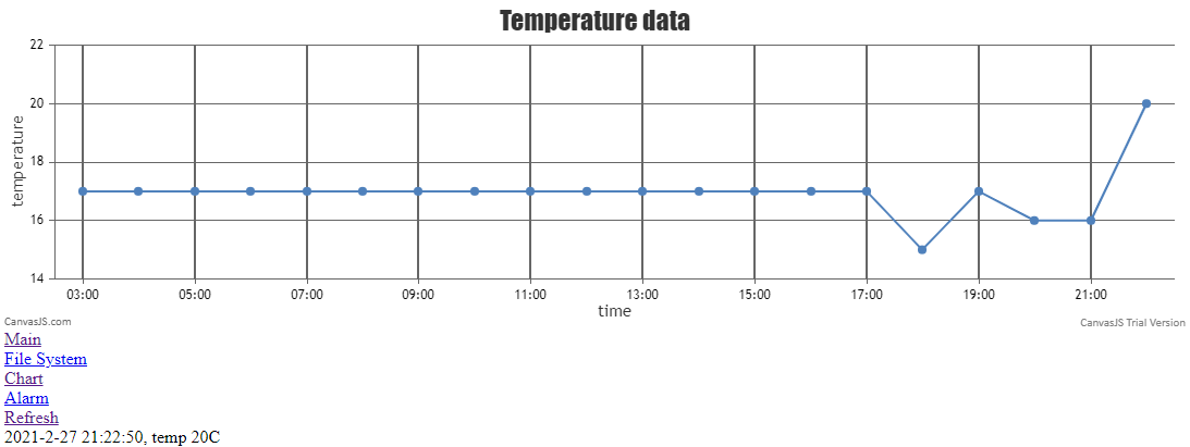
The measurement results from TC74 are integers. The board can display the temperature history on its own website (measurement results are stored in one of the EEPROM memories) and can also transfer them to the Home Assistant.
Generating a chart on PIC18F Of course, the external canvasJS library is used to generate the chart and its javascript file is not on the PIC (although it could, because this solution has some disadvantages, but I do not improve it because ultimately I will use the driver from here in conjunction with Home Assistant).
Below I am placing the page code (HTML + Javascript creating a chart) for those interested:
Code: HTML, XML
Log in, to see the code
The script cc.js :
Code: Javascript
Log in, to see the code
These dataPoints are procedurally generated, measurements are read from EEPROM.
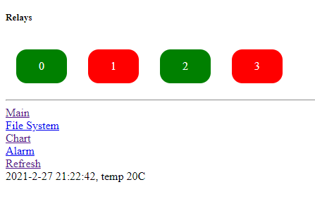
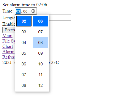
Own website This website is built entirely on PIC. It allows you to control the relays, check the temperature reading (now there is one graph on the website, but you can give several), and set the alarm.
Home:
Temperature graph:
Alarm:
In addition, I started to make a simple filesystem (its support via the web panel and implementation on EEPROM), but finally abandoned this idea. Screenshot of the last version of its panel:
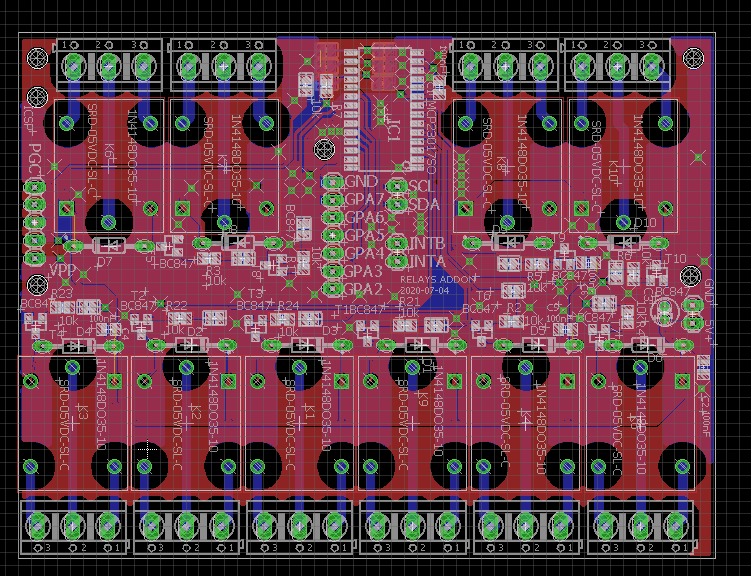
Expansion module support An expansion module can be added to the base board (e.g. with further relays), which will be based on the I2C pin expander. Of course, this will require changing the housing, and I have not yet decided which PCB will be on the top and which on the bottom, but the PCB of the expansion module looks like this:
Compatible with Tasmota HTTP The device supports Tasmota commands sent as GET to HTTP (over TCP) requests according to the following format:
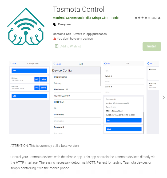
Compatibility with Tasmota Control Since we support Tasmota HTTP, we have compatibility with the Tasmota Control application from Google Play:
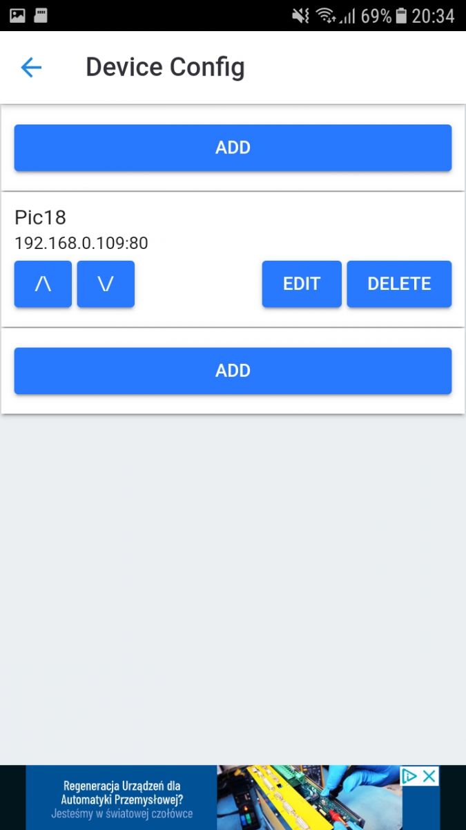
In Tasmota Control, all you need to do is enter the device's bearing and the application detects it immediately:
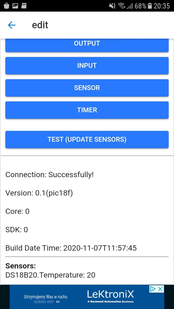
The test passes (the way the device is identified, of course, I can specify in my code, "Build Date Time" is incorrect, entered hard, the DS18B20 is also not really DS, but TC74):
Main control panel (the number of relays and whether there is a temperature available is taken automatically by Tasmota Control):
Home Assistant compatible Compatibility with Tasmota HTTP also ensures compatibility with Home Assistant - thanks to the httas library:
https://github.com/JiriKursky/httas Unfortunately, this library in the github version will not work with the newest Home Assistant, but more on that in a moment.
If you are interested in general what Home Assistant is, I refer you to this topic:
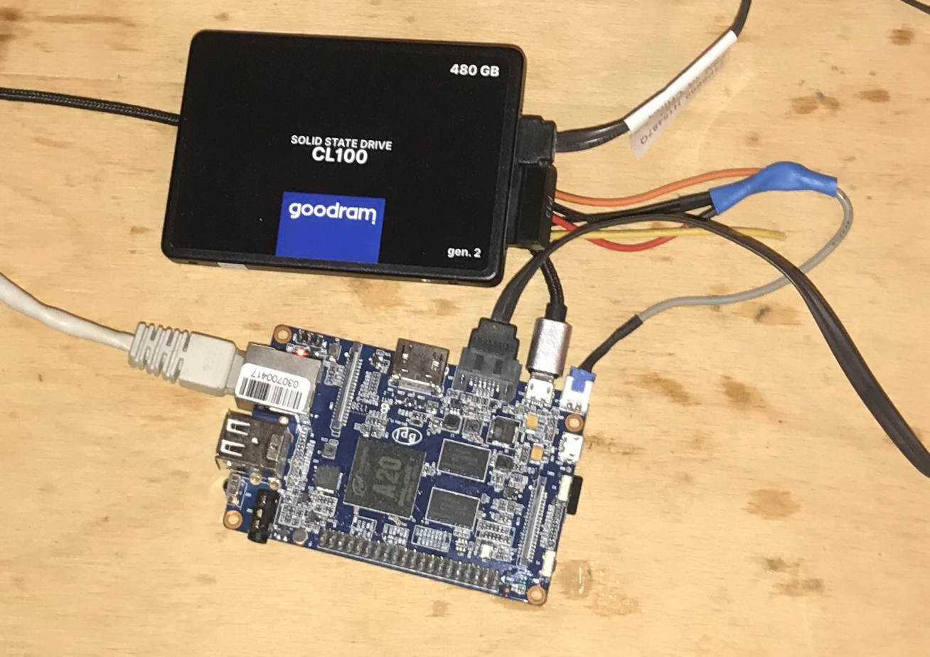
https://www.elektroda.pl/rtvforum/topic3777098.html#19247020 In this topic I used my Home Assistant server placed on Banana Pi:
So first - installing httas for Home Assistant. However, this is not done via the Plugin Store, but manually.
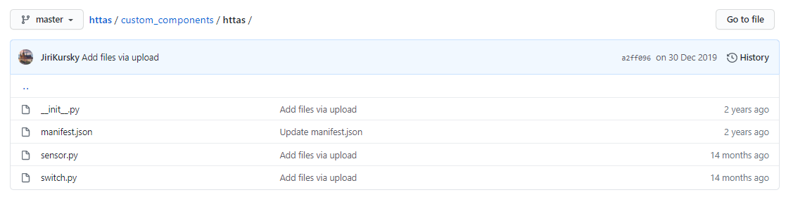
The custom_components / httas folder should be downloaded from the repository:
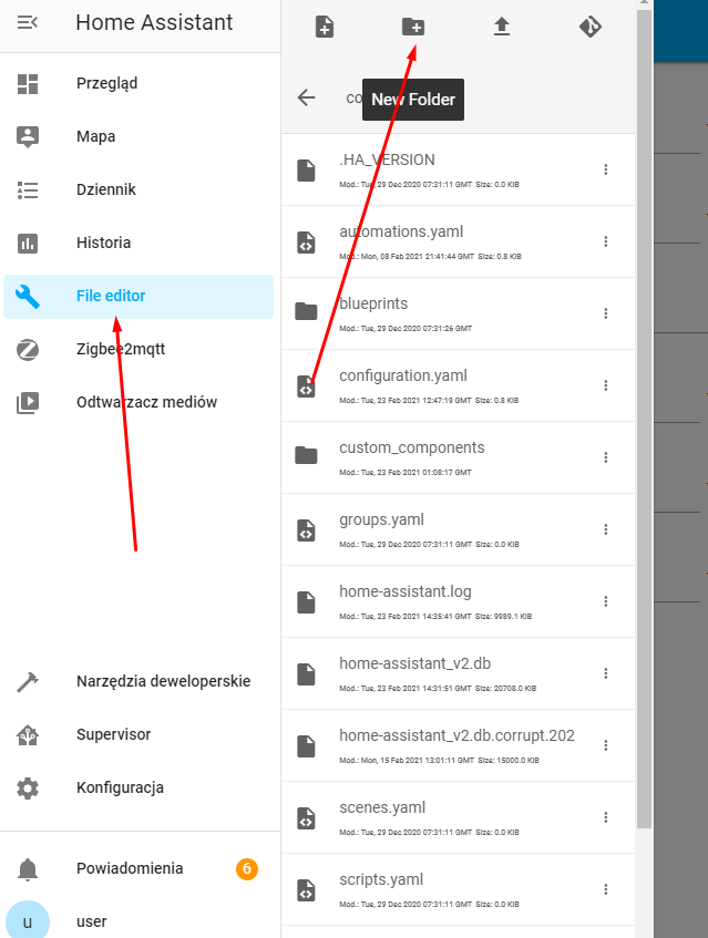
We put this folder in the Home Assistant configuration folder. This can be done via FTP, or via SMB, or 'manually' via File Editor:
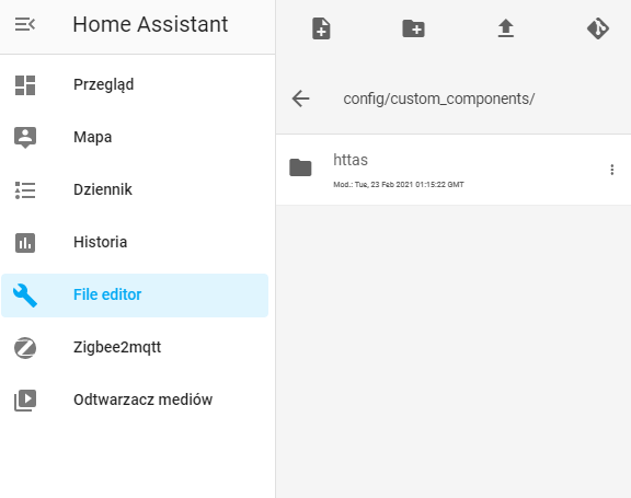
The content of custom_components:
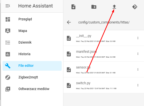
The content of the httas folder after uploading (files are sent via this arrow icon):
Now you have to give the device bearings. In this case, on my driver, but the procedure is the same for any Tasmota HTTP compatible device.
This is done in configuration.yaml:
Code: YAML
Log in, to see the code
The "logger: default: debug" section can be omitted, I added it to make testing easier.
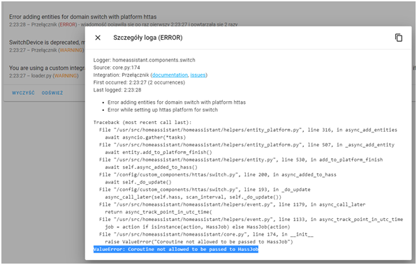
Unfortunately, that's not all, in such a configuration, after starting, we will get an error:
Quote:
Logger: homeassistant.components.switch
Source: core.py:176
Integration: Switch (documentation, issues)
First occurred: 7:46:39 (2 occurrences)
Last logged: 7:46:44
Error adding entities for domain switch with platform httas
Error while setting up httas platform for switch
Traceback (most recent call last):
File "/usr/src/homeassistant/homeassistant/helpers/entity_platform.py", line 315, in async_add_entities
await asyncio.gather (* tasks)
File "/usr/src/homeassistant/homeassistant/helpers/entity_platform.py", line 506, in _async_add_entity
await entity.add_to_platform_finish ()
File "/usr/src/homeassistant/homeassistant/helpers/entity.py", line 530, in add_to_platform_finish
await self.async_added_to_hass ()
File "/config/custom_components/httas/switch.py", line 200, in async_added_to_hass
await self._do_update ()
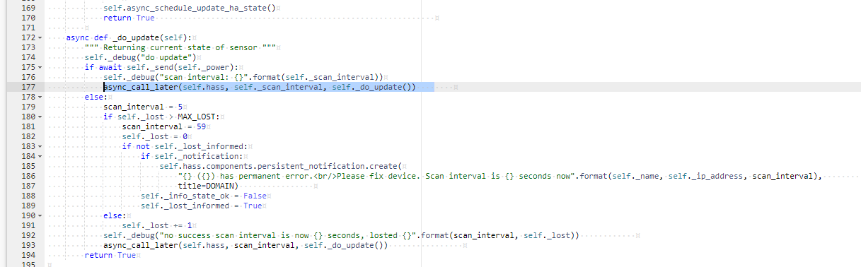
File "/config/custom_components/httas/switch.py", line 193, in _do_update
async_call_later (self.hass, scan_interval, self._do_update ())
File "/usr/src/homeassistant/homeassistant/helpers/event.py", line 1179, in async_call_later
return async_track_point_in_utc_time (
File "/usr/src/homeassistant/homeassistant/helpers/event.py", line 1133, in async_track_point_in_utc_time
job = action if isinstance (action, HassJob) else HassJob (action)
File "/usr/src/homeassistant/homeassistant/core.py", line 176, in __init__
raise ValueError ("Coroutine not allowed to be passed to HassJob")
ValueError: Coroutine not allowed to be passed to HassJob
It's a mistake ValueError: Coroutine not allowed to be passed to HassJob .
However, this is the fault of the library itself. The authors of Home Assistant somehow in 2020 had to change the HassJob system so that it cannot be given corutins in the form of arguments.
You have to fix it yourself (unless the github author will update it soon).
She is guilty, among others. this line:
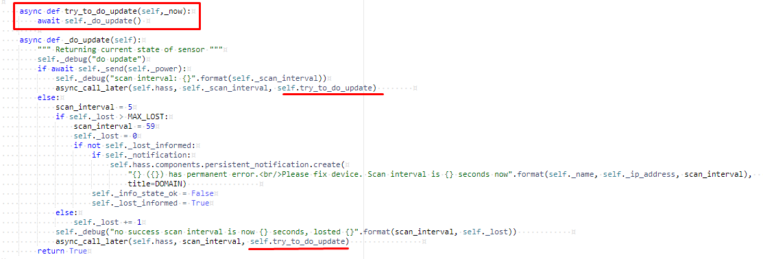
This is easily fixed by splitting the update call into an asynchronous function:
The same type of fixes need to be done in a few more places in the code.
Additionally, I fixed a few other things there, e.g. I didn't like this piece of code (adds redundant & when login variables are empty):
I had to do the same for the second file - sensors.py.
Here is the full final version of the component with my fixes:
httas-fixe...210306.zip (6.91 kB)You must be logged in to download this attachment. Final configuration below (4 relays + 1 temperature sensor):
Code: YAML
Log in, to see the code
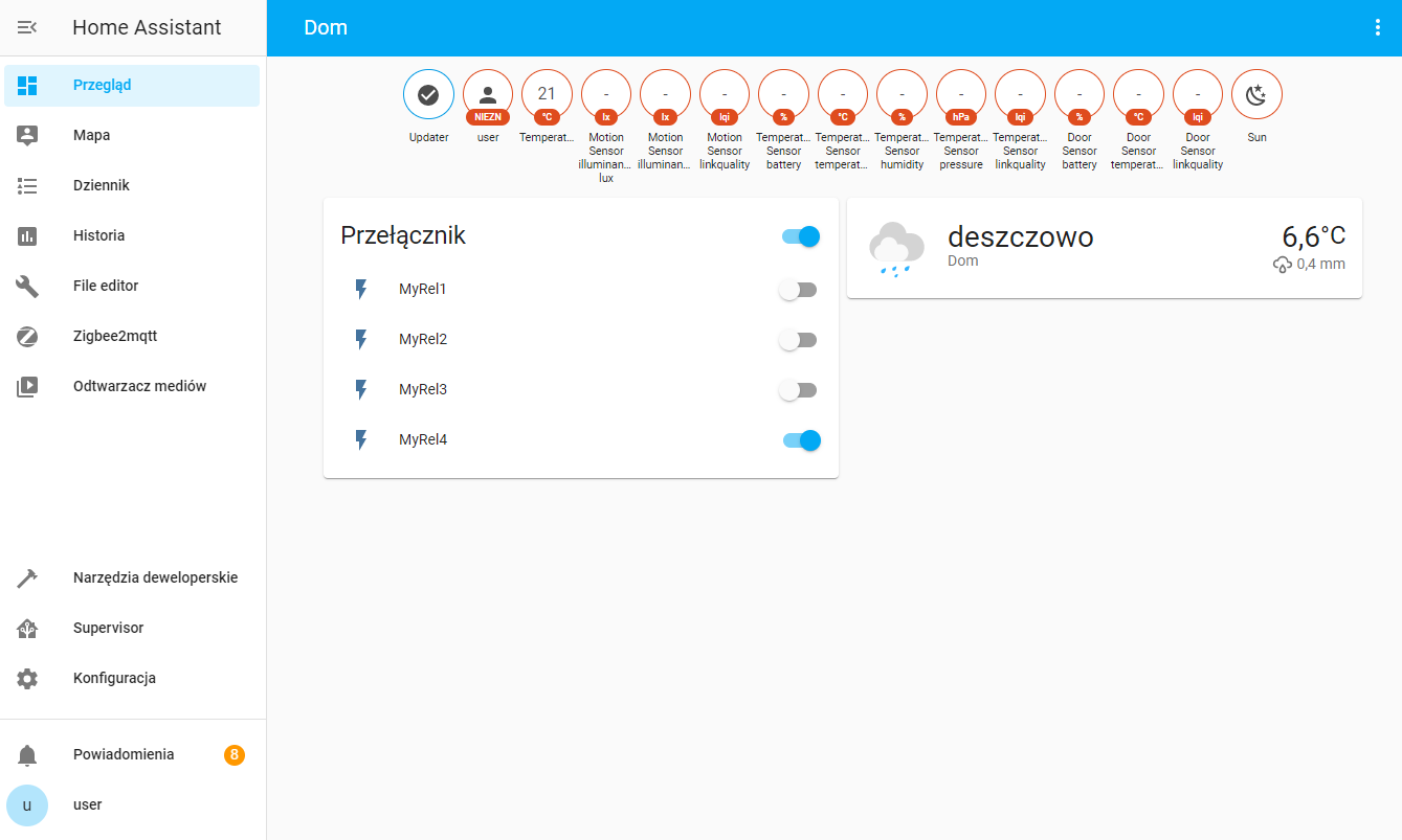
1st presentation in Home Assistant:
Of course, this '21 ° C 'is also from my driver:
And since Home Assistant has access to both relays and to read the temperature from my board, it is easy to do automation such as "turn on relay 2 when the temperature drops below 15 ° C".
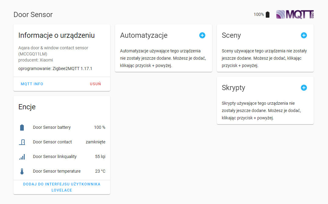
PIC18F67J60 and Automations in Home Assistant The compatibility of my board with Home Assistant allows you to create various types of automation between it and devices from different manufacturers. For example, I will use the Aqara door opening sensor (MCCGQ11LM) and configure it so that 'door opening' activates one relay:
The sensor was previously paired with Home Assistant via CC2531 (because it communicates with Home Assistant via Zigbee):
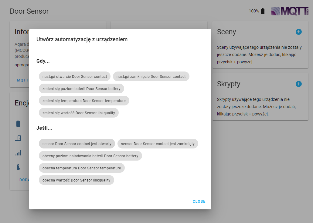
Creating automation:
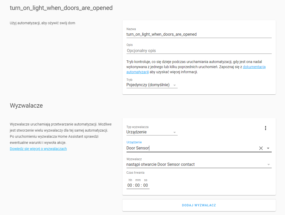
Unfortunately, in order to connect the httas component, you have to go to the Yaml editing mode and finalize the automation there in this way:
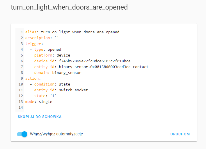
Final version of automation:
Code: YAML
Log in, to see the code
Additionally (for presentation purposes only) I made a similar rule but disabling the relay as the 'door' will open.
Code: YAML
Log in, to see the code
The result of the action in the video:
[movie: 3239091c7f] https://filmy.elektroda.pl/87_1614949999.mp4 [/ movie: 3239091c7f]
The LED is connected to the first relay. As you can see (and hear) the whole thing is very responsive, you don't feel any lags at all.
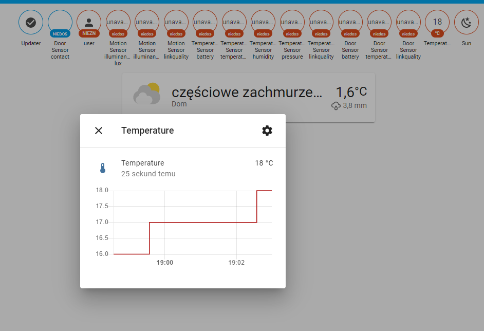
The second example of automation - triggering the relay with the read temperature The second automation that I will show here will only use my controller - it will simply associate the temperature reading from the TC74 with the state of the relay.
Temperature higher than 22 degrees will activate the relay.
We already have the temperature reading:
Now you just need to add the automation in Home Assistant. We will use triggering via numeric_state .
Ready YAML script:
Code: YAML
Log in, to see the code
Similarly, we can add a shutdown trigger ("turn_off" and for example "below: '20'").
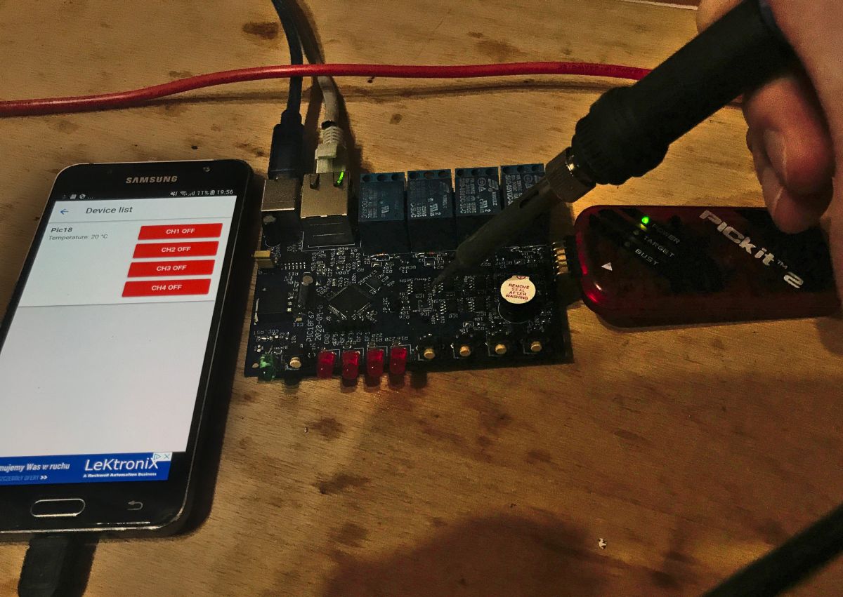
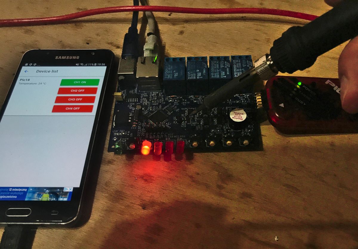
Function test (using TC74 on the PCB and soldering iron as heat source).
Before:
After:
Phone with Tasmota Control beside shown for visualization only (Tasmota Control frequently polls HA for status and HA frequently polls relay driver, so button color updates quickly).
Problems encountered and their solutions I will describe here some specific problems I encountered while creating this project.
To diversify reading, I will put solutions to these problems in 'spoilers', so that the readers can try to think for themselves what was wrong.
Problem 1: TC74, the I2C temperature sensor was working fine and giving good temperature readings until I ran the Ethernet module from the PIC. The very initialization of the Ethernet module from the code level spoiled the temperature readings from I2C. The temperature was starting to float and it could even give readings of 80 ° C
Solution 1:
Spoiler:
It turned out I forgot to give the larger electrolytic capacitor for the 3.3V stabilizer. It was supposed to be 22uF, and there was 1uF + some decoupling 100nF at the pins. And it worked until I ran power-hungry Ethernet in the code. Ethernet itself worked fine, but as you can see, the TC74 still had interference. Of course, the longer cable for the 5V power supply probably also had its impact, and maybe its quality itself.
(initially I was also looking for a solution in the code that maybe I change something with pins, and in the PIC errat, but it's not that)
Problem 2: After implementing the Chart library and initial testing it on PIC, suddenly the page with charts started to load and crash the browser endlessly. I noticed that it crashes only when it has the temperature measurement results from the I2C memory attached, this data 'hard' in the code works.
Solution 2:
Spoiler:
It turned out that this library crashes the browser when it gets data on a graph from a wide range of time, and the EEPROM memory accidentally found a measurement result from 1970, next to it was the result from 2021. So the library began to generate a graph, and began to allocate vertical tick marks and tried to create quite a lot of these ticks, because one for every hour from 1970 to 2021 ... which resulted in the final crash of the browser.
Problem 3: Larger HTML pages (for example, a long time measurement graph) did not open at all - they received no response from the PIC.
Solution 3:
Spoiler:
The PIC used has a limited amount of RAM and only some of its RAM is dedicated to packets. The TCP protocol that HTTP relies on must remember the entire packet because it supports automatic fragmentation and retransmission, if the packet were not kept in RAM the PIC would not know what to resend in the event of a problem. However, I solved the problem not by increasing the RAM allocation for Ethernet, but by separating the creation of the graph data into a separate javascript script that loads separately after loading the basic page with CSS.
Appendix - packets sent via HTTAS Here, I would also like to present the content of sample packages used for communication with Home Assistant for information. It can be useful to someone who tries to implement this protocol himself to pair his own device with Home Assistant (I have the impression that it is simpler than MQTT and equally effective).
Here I am showing the contents of TCP packets, including their HTTP headers.
Home Assistant configuration:
Code: YAML
Log in, to see the code
Home Assistant inquiry sent regularly (status inquiry):
(As for the above package contents, some information there may be outdated because when creating the firmware for my PIC I copied the responses of the original Tasmota from ESP and some of them are hard-coded, e.g. this 'SSId' is obviously not used, you can probably to remove and the package would be shorter, but not everything can be freely changed here, because other devices must "think" that it is Tasmota / ESP because they are compatible with it).
Summary It turns out that it is relatively easy to make a 100% custom PCB that will be compatible with Home Assistant and with pre-built applications such as Tasmota Control. I did this based on the HTTAS protocol which relies on HTTP (which in turn runs over TCP). The next step now will be an additional MQTT implementation, because that will also come in handy, but it's not essential - the system works fine without it.
It was a bit of fun with the project - when implementing this type of system on your own, you even have to program the handling of special characters from HTTP requests, for example the famous% 20 (spaces) or% 3A (a colon, used here when setting an alarm).
The project is constantly evolving. It is possible that soon I will post an extended version on the forum (additional relays) and at the same time I will improve the code and the appearance of the website (so that it looks better, e.g. on mobile devices, larger buttons). Of course, you will also need a larger housing, but in the age of 3D printers, this is not a problem.
About Author
p.kaczmarek2 wrote 14683 posts with
rating 12711 , helped 656 times.
Been with us since 2014 year.
Hi,
Another interesting and successful project. Congratulations. I am glad that you implement your projects on not very popular PIC circuits. If you are looking for someone to help with the implementation... [Read more]
Seba_smd
21 Mar 2021 17:15
Why not popular? Many companies use such companies Nalazek, Proxima and many others. [Read more]
metalMANiu
22 Mar 2021 01:37
@ p.kaczmarek2 As always, a huge dose of information.
Do I understand correctly that all this will only work locally?
Is it difficult to allow safe control of our devices from outside the local network?
... [Read more]
ditomek
23 Mar 2021 08:38
A very nice design. Respect for the post of this size and content. I guess it took a long time to write it.
Our friends from Aliexpress sell very nice relay modules that also have integrated inputs. Everything... [Read more]
p.kaczmarek2
26 Mar 2021 03:06
I know, although I do not prefer to use ready-made modules (because of this plague of projects made of 'blocks' by people who do not understand their internal workings) but with this modbus (I... [Read more]
ditomek
26 Mar 2021 08:23
As for the modules, I am waiting for the package. I am curious how they are made and what they are capable of :-)
For now, I cannot recommend anything with a clear conscience. [Read more]
metalMANiu
28 Mar 2021 17:32
Welcome back.
I often leave home for a few days. So the priority is Internet access.
I'd like to avoid HA server too, but I'm not saying "no". At most, I will buy a raspberry for PLN 330, which... [Read more]
FAQ
TL;DR: Six 24AA256 EEPROMs deliver 192 kB on-board logging, and “the project was created to better understand the operation of IoT and HA” [Elektroda, p.kaczmarek2, post #19330027] The PIC18F67J60 relay driver speaks HTTP/Tasmota, stores graphs, and links to Home Assistant without MQTT.
Why it matters: You can build a fully local, hackable smart-relay hub that still integrates with mainstream home-automation dashboards.
Restart Home Assistant; entities appear instantly. This avoids MQTT and uses simple HTTP polling.
Can I control the relays from outside my LAN?
Yes. Expose Home Assistant via Nabucasa cloud or a reverse proxy; the board stays local while HA handles secure HTTPS access [Elektroda, p.kaczmarek2, post #19342245] Port-forwarding works but is less secure.
Yes. One on-board TC74 plus extra TC74s on long I²C leads log integer °C values every cycle; data is graphed via CanvasJS and stored in EEPROM [Elektroda, p.kaczmarek2, post #19330027]
Yes. The author notes Modbus relay boards are cheap and could replace the discrete relays if you add Modbus handling firmware [Elektroda, ditomek, post #19336171]
What is the maximum number of controllable outputs?


Comments
Hi, Another interesting and successful project. Congratulations. I am glad that you implement your projects on not very popular PIC circuits. If you are looking for someone to help with the implementation... [Read more]
Why not popular? Many companies use such companies Nalazek, Proxima and many others. [Read more]
@ p.kaczmarek2 As always, a huge dose of information. Do I understand correctly that all this will only work locally? Is it difficult to allow safe control of our devices from outside the local network? ... [Read more]
A very nice design. Respect for the post of this size and content. I guess it took a long time to write it. Our friends from Aliexpress sell very nice relay modules that also have integrated inputs. Everything... [Read more]
I know, although I do not prefer to use ready-made modules (because of this plague of projects made of 'blocks' by people who do not understand their internal workings) but with this modbus (I... [Read more]
As for the modules, I am waiting for the package. I am curious how they are made and what they are capable of :-) For now, I cannot recommend anything with a clear conscience. [Read more]
Welcome back. I often leave home for a few days. So the priority is Internet access. I'd like to avoid HA server too, but I'm not saying "no". At most, I will buy a raspberry for PLN 330, which... [Read more]