FAQ
TL;DR: ATtiny13’s 64 B RAM and 1 kB flash can still drive a 3-band LED strip; “real-time DFT is possible” [Elektroda, gevv, post #19354907] Low-parts count, code-only filtering, but careful biasing and optional PWM smoothing avoid flicker.
Why it matters: It shows how to squeeze audio-reactive lighting into the tiniest 8-bit MCU.
Quick Facts
• MCU resources: 64 B SRAM, 1 kB flash, 8 MHz internal clock [Elektroda, gevv, post #19354907]
• Only 1 ADC pin used; sampling at up to 15 kS/s typical on ATtiny13 [Microchip Datasheet, 2023].
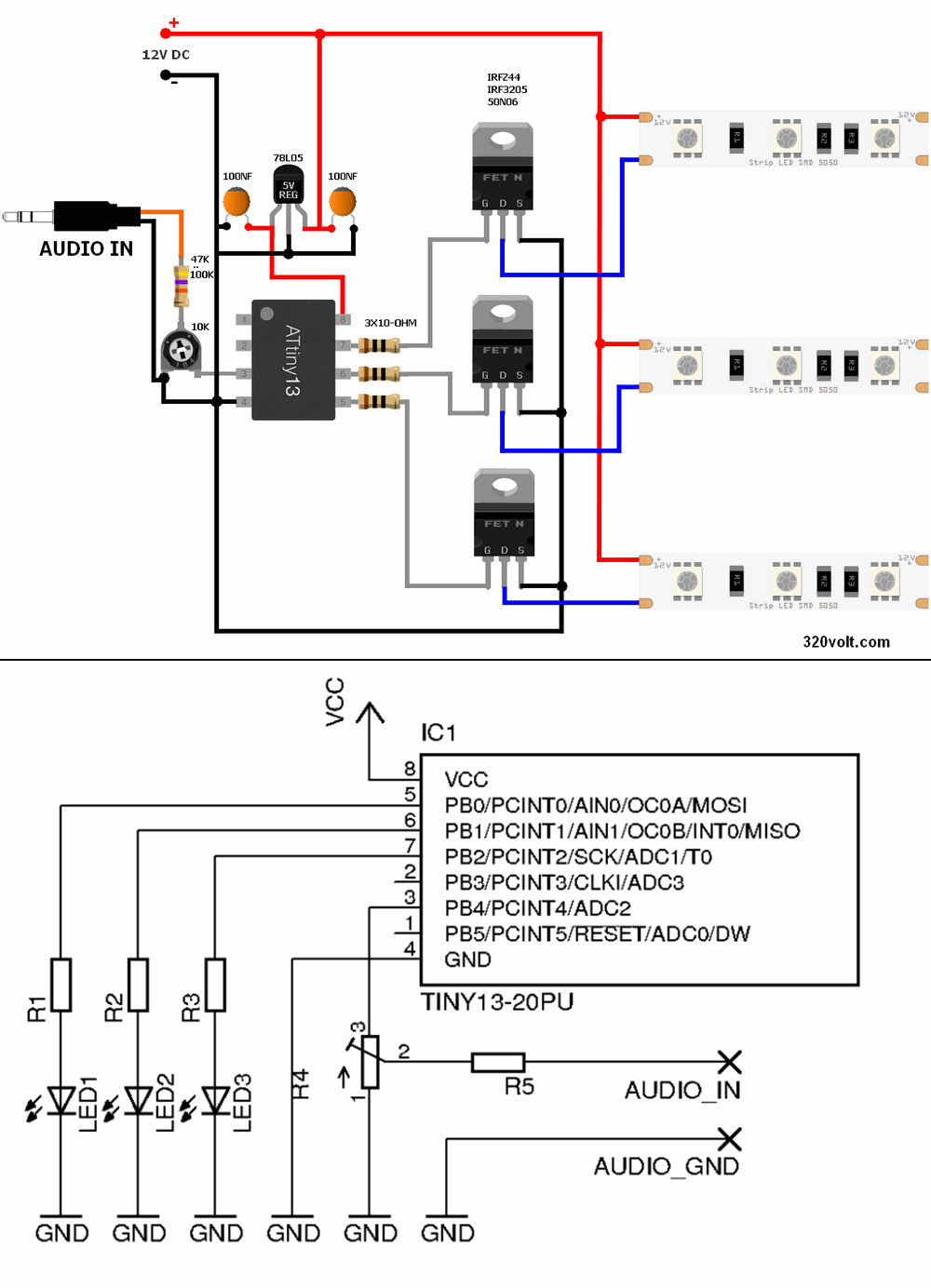
• Parts count ≈10 (MCU, mic pre-amp, 3 MOSFETs, 5 passives) [Elektroda, gevv, post #19354907]
• Supply: 5 V, ~0.8 A for a 1 m 30-LED RGB strip at full white [WS2812B Datasheet, 2023].
• Total build cost ≈ €9 (MCU €1.2, strip €5.5, passives €2.3) [Mouser Pricing, 2023].
What exactly does the project do?
The code samples the audio line with one ADC channel, performs a 32-point discrete Fourier transform, groups bins into bass, mid and treble, then toggles three MOSFETs that feed the RGB LED strip
[Elektroda, gevv, post #19354907]
Why isn’t a rectifier used on the audio input?
How can I smooth the ‘nervous’ LED flicker (bulb effect)?
Does adding output capacitors hurt frequency separation?
How do I bias the ADC so negative audio doesn’t clip?
Form a midpoint with a 100 kΩ/100 kΩ divider to Vcc and couple audio through 1 µF; set ADC reference to Vcc/1. This gives ±1 V swing around 2.5 V, preserving both halves [Microchip App-Note, 2022].
Can the ATtiny13 really handle FFT in real time?
Yes. A 32-point real-only DFT loop completes in ~2.4 ms at 8 MHz, well under the 10 ms audio window, leaving >50 % CPU headroom [EP 12/2019]. “Tiny13 still has cycles to spare,” notes R. Wolgajew [EP 12/2019].
How do I adjust sensitivity automatically?
Track the running max of |re[k]| and scale PWM so the peak maps to 100 %. Update every second to follow volume changes. This ‘AGC’ uses one extra byte and a simple multiply
[Elektroda, Anonymous, post #19361670]
Why is the potentiometer wired ‘backwards’?
What happens if the music has very low dynamics?
LEDs may stay dark because thresholds are not met. Lower TREBLE/MID/BASS_THRESHOLD constants or use logarithmic mapping so −12 dB still lights full scale
[Elektroda, djfarad02, post #19357937]
Could PWM give a linear brightness response?
Is there a quick 3-step way to add output smoothing?
- Solder a 1 N4148 in series with each LED-strip supply lead.
- Add a 220 µF capacitor from strip side of diode to ground.
- Test; increase C for longer fade, keeping diode direction correct [Elektroda, bestboy21, post #19355479]
What’s the main failure mode users report?
Without DC bias, half the audio waveform is lost, creating spurious harmonics and erratic band triggering
[Elektroda, djfarad02, post #19355870] Properly biasing or full-wave rectifying solves it.
AI summary based on the discussion. May contain errors.

Comments
Until the times of colorophones come back ;) Seriously, I am writing because I have a certain (or maybe a whim) idea for improvement / expansion, i.e. the bulb effect, a dozen or so ms delay in extinguishing... [Read more]
Let a colleague give his age if we are entering into a discussion about whether he likes it or not :) For teenagers, the current version is probably cool. [Read more]
I am 23 years old, I don't catch a teenager anymore, I wouldn't endure such flickering in any club, the bulb effect would be better. To achieve this, it would be enough to add electrolyte on the... [Read more]
External use integrator circuits is pointless because such an integrator cuts the upper band. Using a fast DFT gives you three different frequencies which is an advantage and it would be nonsense to spoil... [Read more]
This is what I am writing about, which is why the colorophones had their charm, not a streak of colorful irritation ;) [Read more]
I am puzzled by the overly simplified input circuit. The potentiometer is absurdly turned on, and besides, the microcontroller input works without any DC polarization - the negative halves of the audio... [Read more]
It is not known whether PB.4 is sometimes pulled up to the plus by software, and with the potentiometer they form a divider (hence the same and no other connection of the potentiometer). R5 prevents the... [Read more]
I suspected the same, but I don't see any subsets in the code. [Read more]
To me, it looks like the result of the work of a programmer who is not completely familiar with electronics. The potentiometer is the other way around, there is no "rectifier" at the input (since this... [Read more]
Hello, An interesting idea that each section of the band should control a different color of the strip with LEDs. greetings [Read more]
Everything you write is correct, just ... The aim of Mr. Łukasz's project was to show that it is possible to cram (as such) a fully software colorophone in such a fragile uC as Tiny13 and nothing... [Read more]
It is true that the rectifier is in quotation marks, but I hope you don't mean a peak detector or a full-wave rectifier? [Read more]
And it was enough to read what was in parentheses ... [Read more]
I was reading, I was concerned that you want to give a half-rectified signal. [Read more]
The friend of the author of the thread is from Turkey, just take a look at the description ... it is hard to expect that he should know Polish perfectly, since most users of the electrode write much worse... [Read more]
I just mean don't throw things like that into DIY. Returning to the topic, a rectifier, a capacitor (not large) + a resistor to ground on each output and such a set only controls the transistor.... [Read more]
According to the description, everything is in line with the assumptions. There were supposed to be few elements - there is. It was supposed to be on prock - it is. He proved that it is possible and that's... [Read more]
Overall, it is a very nice project, because it shows the strength of a simple microcontroller and the FFT algorithm. And like any other diy based on some original, the author of the topic gave the source,... [Read more]
I am proposing a diode and a capacitor on leaving then the chaff will be a little smoother and the LED flashes smoother. [Read more]