logo elektroda
logo elektroda
X
logo elektroda
ADVERTISEMENT
Treść została przetłumaczona polish » english Zobacz oryginalną wersję tematu
  • Hello,

    This experimental project shows how to use ATtiny13 to sync live music and lights with just a few extra components. The design uses a single ADC (analog-to-digital converter) channel for signal acquisition and some DSP (digital signal processing) calculations that separate the three frequency bands in real time and make the LEDs dance in sync with the music. This project also proves that real-time DFT (Discrete Fourier Transformation) is possible on a small MCU like the ATtiny13, which only offers 64B of RAM and 1024B of FLASH memory.


    ( video; RGB led strip, separate led strip and microphone preamplifier )
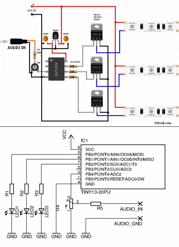

    Music Dancing LEDs (led strip)

    file: codes, pcb v1-v2

    source; blog.podkalicki.com/attiny13-dance-lights-with-dft/

    Cool? Ranking DIY
    About Author
    gevv
    Level 12  
    Offline 
    gevv wrote 112 posts with rating 507. Live in city istanbul. Been with us since 2007 year.
  • ADVERTISEMENT
  • #2 19355479
    bestboy21
    Level 40  
    Until the times of colorophones come back ;)
    Seriously, I am writing because I have a certain (or maybe a whim) idea for improvement / expansion, i.e. the bulb effect, a dozen or so ms delay in extinguishing would add a bit of charm, because in my eye it flickers too nervously, maybe a matter of taste but I I wouldn't be able to endure something like that for a long time.
    A change in the software or even an integrator circuit at the output with 100-500uF electrolyte, I think it would add a little warmth to this torture tool 8-)
  • #3 19355630
    czareqpl
    Level 33  
    bestboy21 wrote:
    Until the times of colorophones come back ;)
    Seriously, I am writing because I have a certain (or maybe a whim) idea for improvement / expansion, i.e. the bulb effect, a dozen or so ms delay in extinguishing would add a bit of charm, because in my eye it flickers too nervously, maybe a matter of taste but I I wouldn't be able to endure something like that for a long time.
    A change in the software or even an integrator circuit at the output with 100-500uF electrolyte, I think it would add a little warmth to this torture tool 8-)


    Let a colleague give his age if we are entering into a discussion about whether he likes it or not :)
    For teenagers, the current version is probably cool.
  • #4 19355683
    U92
    Level 10  
    I am 23 years old, I don't catch a teenager anymore, I wouldn't endure such flickering in any club, the bulb effect would be better.
    To achieve this, it would be enough to add electrolyte on the strip feed for each color
  • ADVERTISEMENT
  • #5 19355821
    Anonymous
    Level 1  
  • #6 19355830
    bestboy21
    Level 40  
    U92 wrote:
    bulb effect would be better.


    This is what I am writing about, which is why the colorophones had their charm, not a streak of colorful irritation ;)
  • #7 19355870
    djfarad02
    Level 19  
    I am puzzled by the overly simplified input circuit. The potentiometer is absurdly turned on, and besides, the microcontroller input works without any DC polarization - the negative halves of the audio signal will be cut off.
  • #8 19355923
    Justyniunia
    Level 36  
    It is not known whether PB.4 is sometimes pulled up to the plus by software, and with the potentiometer they form a divider (hence the same and no other connection of the potentiometer). R5 prevents the signal from shorting to ground in the lowest position.
  • #9 19355996
    djfarad02
    Level 19  
    Justyniunia wrote:
    It is not known whether PB.4 is sometimes pulled up to the plus by software, and with the potentiometer they form a divider (hence the same and no other connection of the potentiometer). R5 prevents the signal from shorting to ground in the lowest position.

    I suspected the same, but I don't see any subsets in the code.
  • #10 19356207
    398216 Usunięty
    Level 43  
    To me, it looks like the result of the work of a programmer who is not completely familiar with electronics.
    The potentiometer is the other way around, there is no "rectifier" at the input (since this is to control the audio signal, it would be appropriate to at least give the entire signal, not a half) and the nervous operation of the LED.
    In general, the very name ILUMINOPHONY was created for the first systems that convert the value of a signal at a certain frequency into the brightness value of a specific color. Besides, the name is Polish - abroad you could meet other LIGHT ORGAN or similar.
    The rule was that color-filtered spotlights projected beams of light onto the wall / screen. The louder the given frequency in the signal, the brighter the reflector shone. So there was no "dead threshold" below which it did not shine at all. These types of circuits, however, were quite complicated; Therefore, simplified versions working "zero-one" (more or less as above) and numerous versions were quickly created - from the simplest (where simple LC filters and light bulbs were connected to the amplifier output), to more complicated (and safer for the amplifier) by the way) with a line signal input, preamplifier and adjustable (sensitivity) active filters that control thyristors or triacs through galvanic separation systems ...
    Depending on the power of the bulbs used, it was possible to obtain greater or less "gentleness" of operation - sometimes desirable and sometimes not - especially when the fourth channel was negated (it was on in the absence of signal / music). There were also many different combinations that assigned a given frequency range to a color. From the beginning, the colors were basically "basic" red, blue and ... green (hence quotation marks) or - for four-channel installations - additionally yellow. Yellow instead of green appeared less frequently in the 3 color phones.
    The layout from the subject was, in my opinion, modeled on the operation of such simple systems with active filters and operating zero-one, but the author did not take into account that he controls light sources with even zero inertia - as a result, the effect is somehow, but (in my opinion also) a bit too nervous. Adding capacity ... hmmm might help, but a definitely better solution would be to return to the precursors of Illuminophony - to systems with the brightness of colored lights depending on the signal level.
  • ADVERTISEMENT
  • #11 19356253
    conisl
    Level 11  
    Hello,

    An interesting idea that each section of the band should control a different color of the strip with LEDs.

    greetings
  • #12 19356255
    Justyniunia
    Level 36  
    Everything you write is correct, just ...
    The aim of Mr. Łukasz's project was to show that it is possible to cram (as such) a fully software colorophone in such a fragile uC as Tiny13 and nothing else. This, in my opinion, is a big feat.

    So let's comment on the layout built (?) By the author of the thread, not the program itself, and that there is nothing to comment on, that's another matter.

    I don't really understand the idea behind this topic.
    The author has not included his diagram, not his program
    He even translated the title alive from the original ... (maybe at least a video?),
    No building materials, nothing.
    What is DIY? And what are these pluses for?

    Well, unless the author of the topic and the author of this whole project are the same person, I would like to pay you back.

    However, if not, then I am applying for a transfer of this thread to another section (I don't know, articles?), And certainly a kick from DIY Constructions.
  • #13 19356315
    djfarad02
    Level 19  
    398216 Usunięty wrote:
    The potentiometer is the other way around, there is no "rectifier" at the input

    It is true that the rectifier is in quotation marks, but I hope you don't mean a peak detector or a full-wave rectifier?
  • #14 19356331
    398216 Usunięty
    Level 43  
    djfarad02 wrote:
    hope you don't mean peak detector or full-wave rectification?
    And it was enough to read what was in parentheses ...
    398216 Usunięty wrote:
    since this is to be an audio signal control, it would be appropriate to at least give the entire signal, not a half
  • #15 19356341
    djfarad02
    Level 19  
    398216 Usunięty wrote:
    And it was enough to read what was in parentheses ...

    I was reading, I was concerned that you want to give a half-rectified signal.
  • #16 19356401
    Slawek K.
    Level 35  
    Justyniunia wrote:

    He even translated the title alive from the original ... (maybe at least a video?),
    No building materials, nothing.

    The friend of the author of the thread is from Turkey, just take a look at the description ... it is hard to expect that he should know Polish perfectly, since most users of the electrode write much worse than him.

    Greetings
  • #17 19356539
    Justyniunia
    Level 36  
    I just mean don't throw things like that into DIY.

    Returning to the topic, a rectifier, a capacitor (not large) + a resistor to ground on each output and such a set only controls the transistor. This is how I see it.

    I once wrote to the author of this project with a request to send a hexa. I built a layout. It works, cool, unfortunately it is far from being a colorophone and it is not even about the lack of a time constant.
    There is frequency division, but it's hard to tell which channel is responsible for what.
    The second thing - you have to give him a very small signal to enter.
  • #18 19356682
    398216 Usunięty
    Level 43  
    According to the description, everything is in line with the assumptions. There were supposed to be few elements - there is. It was supposed to be on prock - it is.
    He proved that it is possible and that's it. There was no way it was supposed to work well - important that it works at all.
    I built the same effect when I was ten years old using the scheme from ABC Technika. There, the whole thing was implemented on four transistors and several resistors and capacitors. It worked similarly, although in that project the light bulbs from the flashlight were controlled (because no one even heard about LEDs then). It is true that I converted it to control triacs (some Czech KT205 probably?) And the separation was done on a transformer - the input signal was fed to the primary input and the secondary input to the follower (first transistor), the other transistors controlled the gates directly. Power supply from some bell transformer ...
  • #19 19356823
    Anonymous
    Level 1  
  • #20 19356845
    Justyniunia
    Level 36  
    I am proposing a diode and a capacitor on leaving then the chaff will be a little smoother and the LED flashes smoother.
  • #21 19356888
    Anonymous
    Level 1  
  • ADVERTISEMENT
  • #22 19357730
    398216 Usunięty
    Level 43  
    acctr wrote:
    So instead of a linear function or a more sophisticated log type, we have an ordinary step function.

    I wrote about it in the 10th post. Sure, it can be eliminated programmatically to some extent, but it will still not be a purely linear relationship as in "real" illuminophony (I also wrote about it).
  • #23 19357937
    djfarad02
    Level 19  
    398216 Usunięty wrote:
    Sure, it can be eliminated programmatically to some extent, but it will still not be a purely linear relationship

    Programmatically, it is possible to obtain a purely linear relationship (using PWM). Why should he not give up?

    However, such dependence does not guarantee the best effect. As a rule (especially for modern music with low dynamics) the effect will be better if a certain range (eg 0 .. -12dB) is mapped to the full spectrum of brightness. For lower signals, let brightness be 0.

    acctr wrote:
    As for the comments about the lack of a rectifier at the audio input - everything is fine, because of one line in the code:
    Code:
    re [k] + = W [a% N] * samples [n];

    for negative halves of samples [n] is zero, which is as if there was no signal


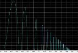
    I am not sure if everything is okay for sure. Maybe I don't understand how the algorithm works, but the sinusoidal signal of = 100Hz after cutting one half has the following spectrum:
    Music Dancing LEDs (led strip)
    How does the algorithm remove the resulting harmonics?
  • #24 19361343
    Justyniunia
    Level 36  
    @acctr
    I can see that you are in this language kumaty.
    Tell me such a thing ...
    1. Is it hard to separate the middle tones from the highs by software?
    2. Add an automation system (increase the "sensitivity" of the ADC until all the LEDs "live" and maintain this level)?
  • #25 19361670
    Anonymous
    Level 1  
  • #26 19438493
    lpodkalicki
    Level 1  
    Hi,

    I found this thread by accident and decided to add something. There are many correct observations here regarding, among others, analog signal input for this circuit. Positive analysis signal was sufficient for this simple experiment. In the first iteration, it was supposed to be a simple layout and I focused mainly on the programming part. In the so-called in the meantime, more versions were created, which gave _ much_ a better visual effect and the scheme was less dazzling in the eyes. Details are described in EP 12/2019. I talked a lot about this project with Ryszard Wolgajew from EP, who made some interesting projects based on these algorithms - incl. spectrum analyzer, and a small illuminophony, which I recommend for analysis if someone likes DSP on small MCU.

    Thanks for your interest in the project!

    greetings
    / LP

Topic summary

The discussion revolves around an experimental project utilizing the ATtiny13 microcontroller to synchronize music with LED strip lighting through real-time digital signal processing (DSP). Participants express various opinions on the project's design, particularly the LED flickering effect, suggesting improvements such as adding a delay for a smoother transition and discussing the input circuit's simplification. Concerns are raised about the lack of a rectifier for the audio signal and the overall effectiveness of the DFT algorithm implemented. Some contributors highlight the project's educational value in demonstrating the capabilities of small microcontrollers and FFT algorithms, while others critique the implementation details and suggest enhancements for better visual effects.
Summary generated by the language model.
ADVERTISEMENT