QTouch WiFi switch plugged into L cable only - test, interior, diagram
TL;DR
- The qTouch WiFi/RF433 glass wall switch works from the L wire only, so it can be installed without an N conductor.
- Inside, an ESP8285 with 1MB flash handles WiFi, while an RF433 chip simulates touch presses and keeps paired remotes working after firmware changes.
- The mains side uses a triac design with a BTA16-600B and MOC3063, plus an MPX 0.33uF capacitor "adapter" and 3 x 1000uF smoothing capacitance.
- Tasmota flashed successfully over UART; pin mapping was D6 for relay, D7 for LED, and D3 for button, and the RF remote still worked.
Generated by the language model.
Hello my dears. .
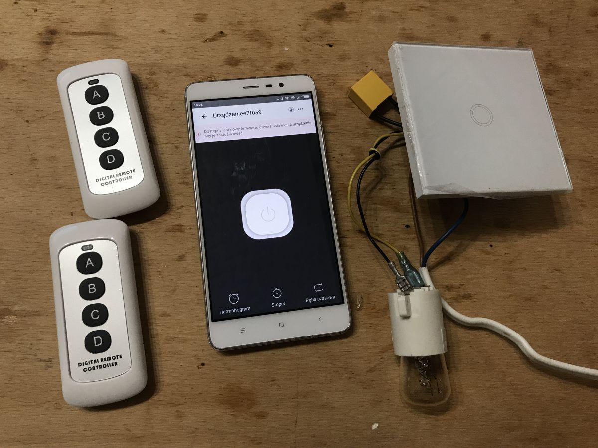
I will test and take apart here the qTouch WiFi/RF433 light switch, which is distinguished from other products of this type by the fact that it only plugs into the L wire, meaning that it will work even if we don't have an N led to the box.
I will test this switch with the eWeLink application, but then I will also upload Tasmota to it and show its pin configuration so that we can use it with our own software.
Finally, I will draw a diagram of it.
It will be interesting because this switch, unlike the previously reviewed products, is realised on a triac and not on a relay.
Related topics .
I have already written several topics on WiFi-based ESP products. I mainly show the interiors there.
I also describe there the process of programming such a switch and using it with a manufacturer's app (Blitzwolf, SmartLife, Tuya, eWeLink) or Tasmota.
I recommend that you familiarise yourself with these topics, I won't repeat all the information several times and they generally apply to all such products.
List below:
- BW-LT30 i.e. WiFi adapter for bulb - test, teardown and ESP firmware upload .
- WiFi-controlled electrical socket - BW-SHP8 - commissioning and testing
- Test and interior of the BW-SS3, a WiFi controlled light switch from Blitzwolf .
- Socket/plug with WiFi PS-16-M and eWeLink/Coolkit app - test and teardown
- SmartLife switch - test, teardown and programming of light switch on WiFi (similar switch but without RF and description of programming it in Arduino via cables)
- The SC3-01 SmartLife switch and ESP firmware upload via WIFI (tuya-convert/OTA) (this time programming via WiFi, no need to open the case, no soldering of cables)
In addition, a second topic on Tasmota:
- ESP8266 and Tasmota - WiFi relay control step by step .
In addition, I recommend a topic about Home Assistant (which can control a collection of such devices):
Home Assistant tutorial - configuration, WiFi, MQTT, Zigbee, Tasmota .
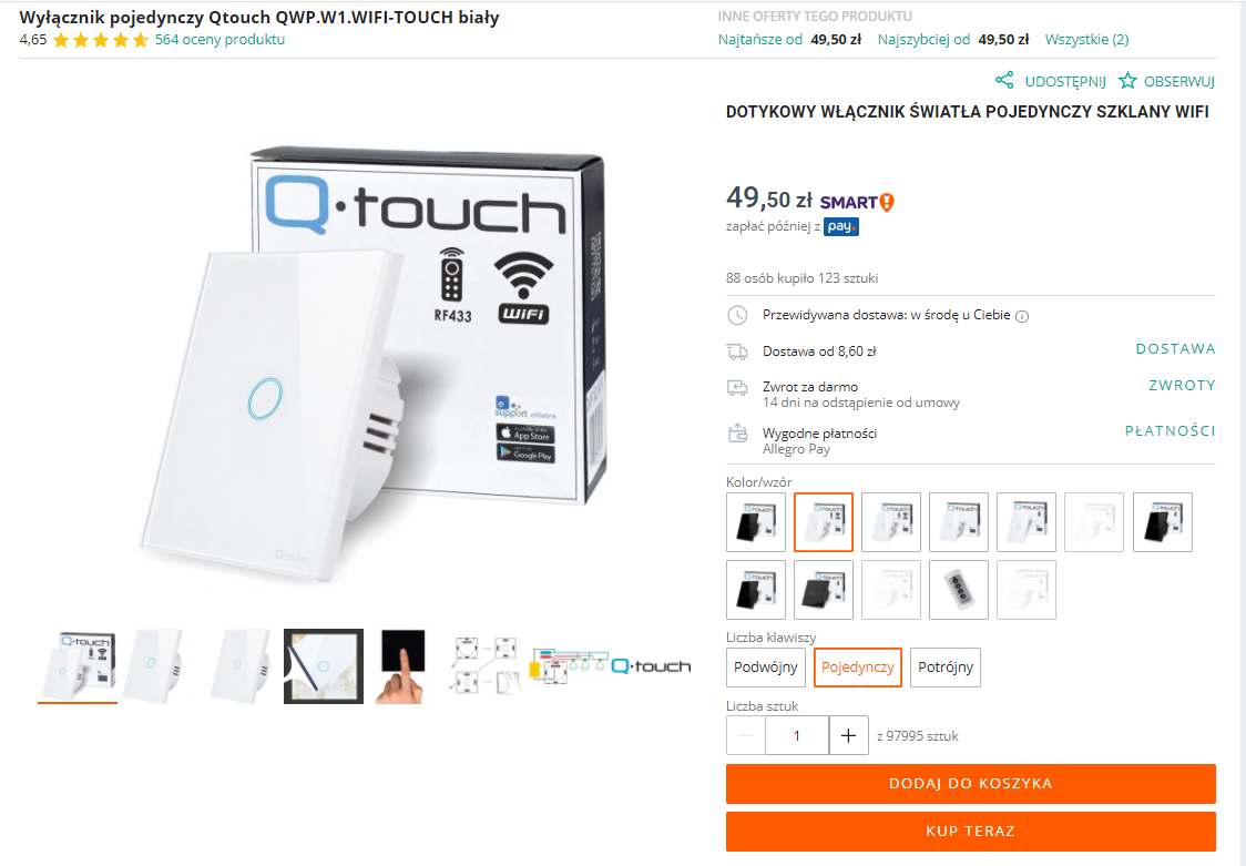
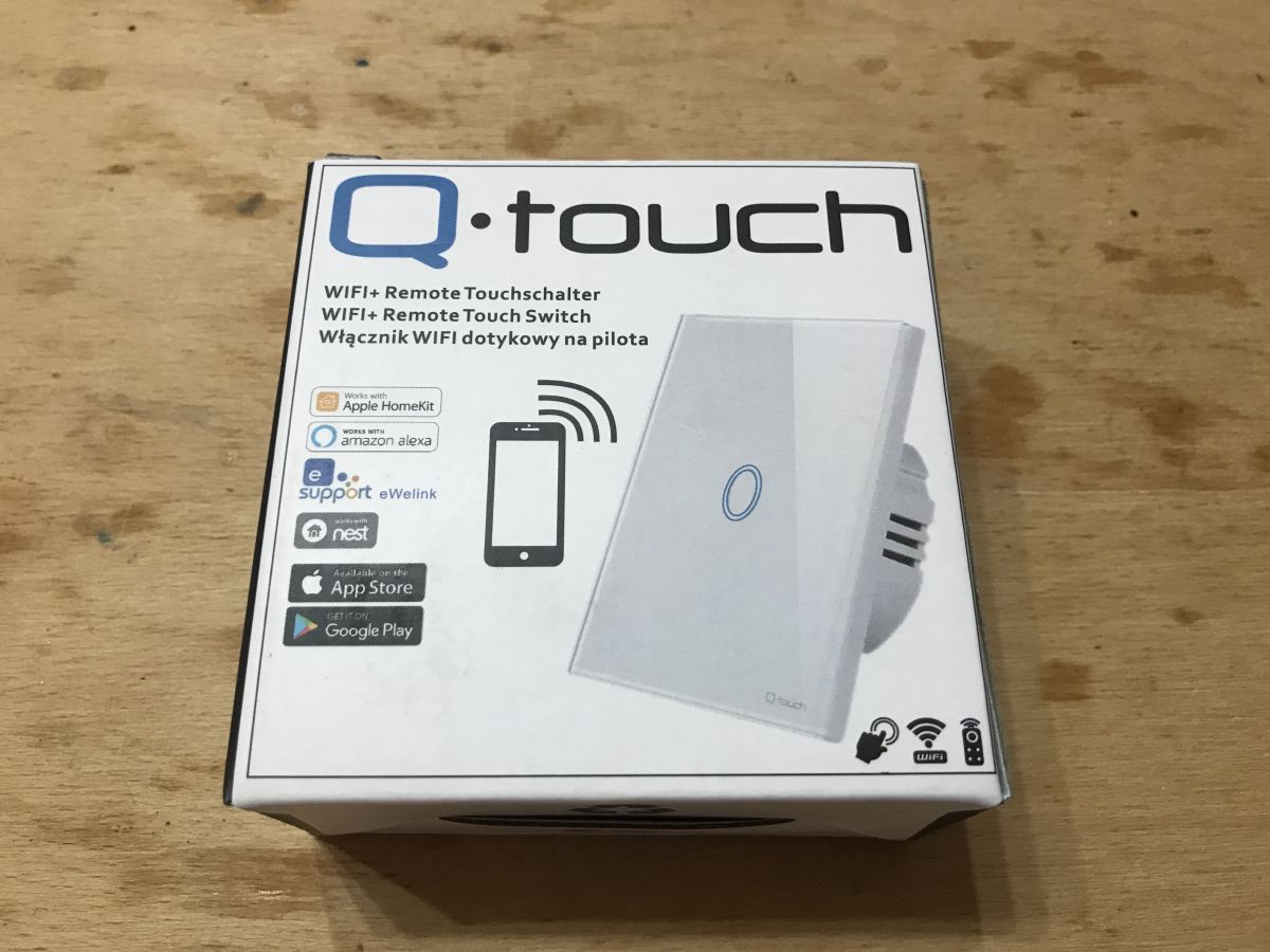
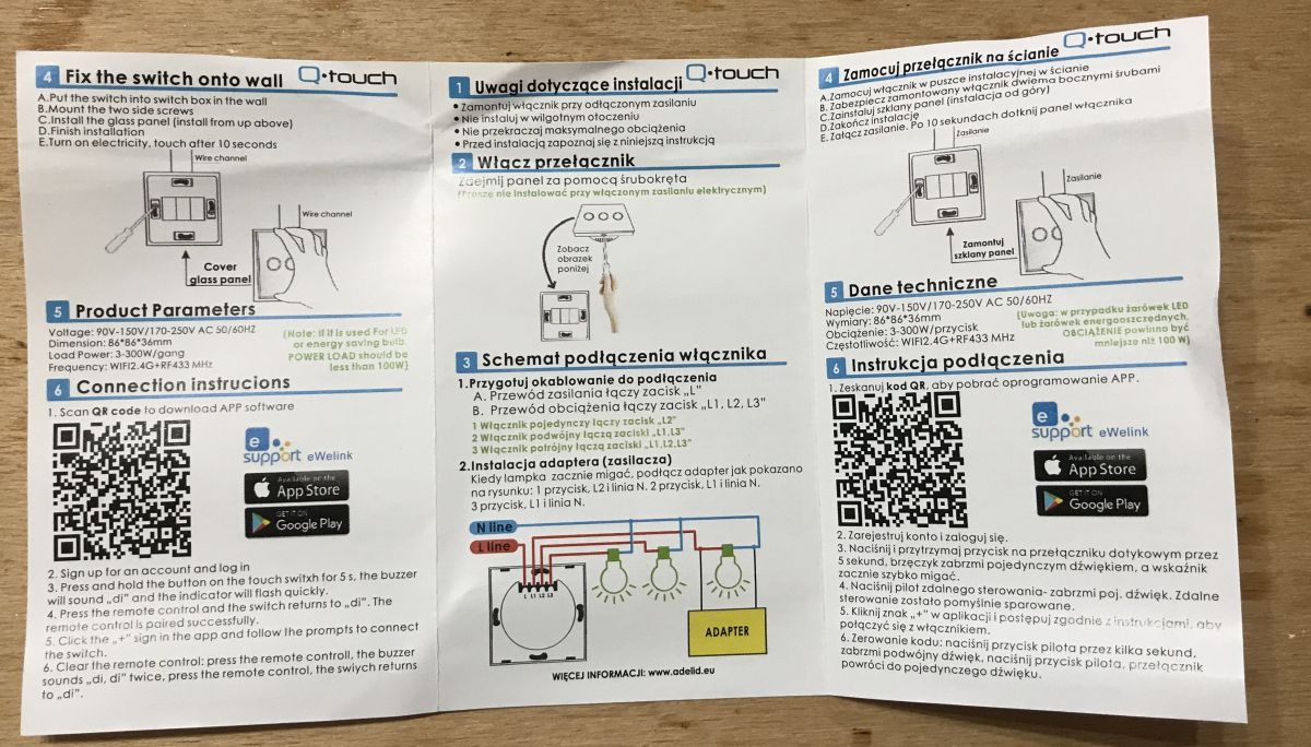
Purchase qTouch .
The product can be purchased in Poland on various mail order portals under the heading Touch Light Switch Single Glass WIFI . The product comes in two colours (black and white) and in three combinations (one button, two, three):
 .
.
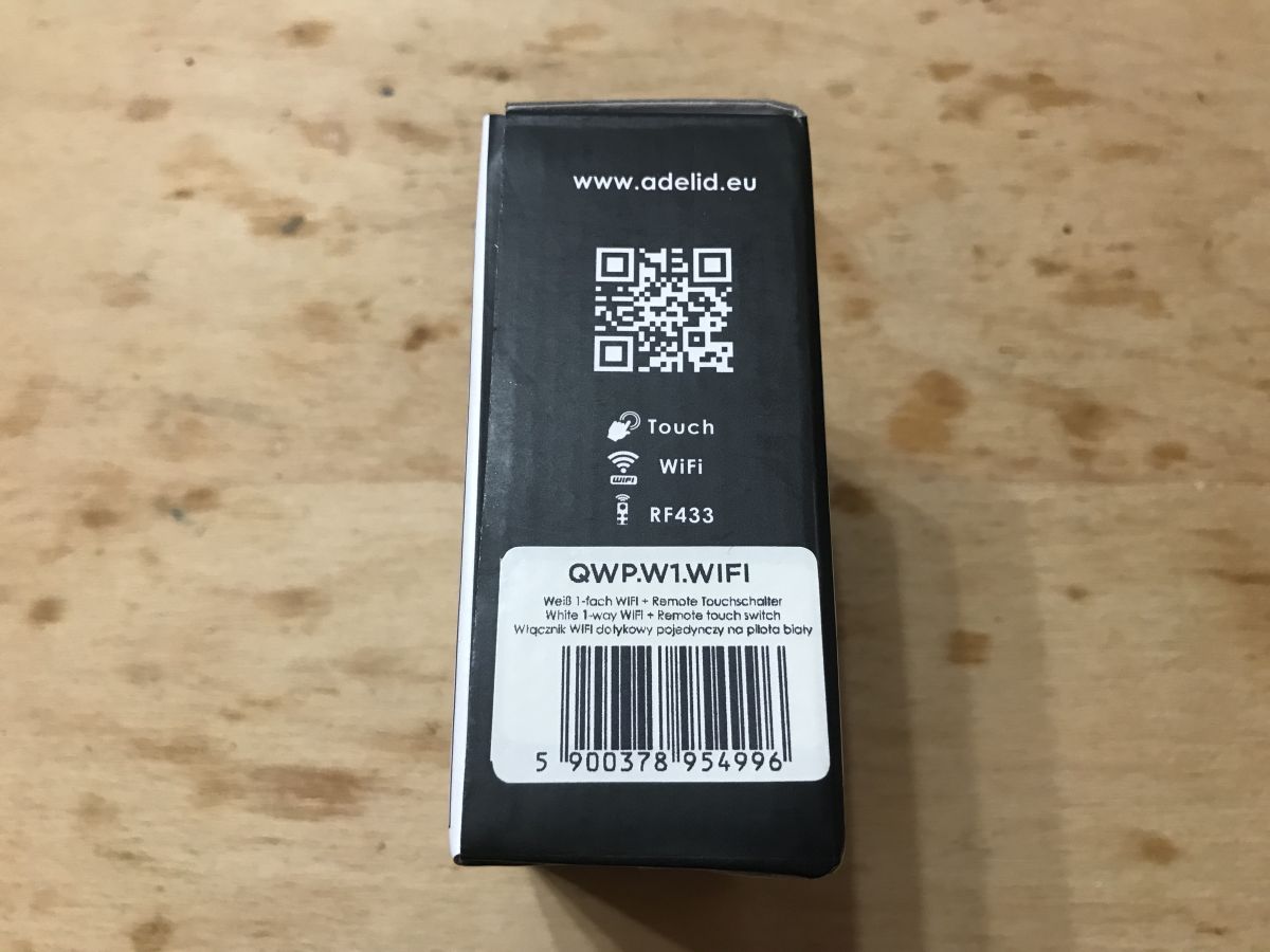
Product code: QWP.W1.WIFI-TOUCH
The vendor states the following parameters:
Quote:..
Technical data:
Number of buttons: 1,
Material: Glass panel / plastic
Voltage: 230V AC,
Energy consumption: 0,02W
Frequency: 50/60 Hz,
Panel dimensions: 86x86x9 mm,
Load power: 3-300W / button (100W for LED),
Relative humidity: 10%-93% (non-condensed),
Endurance: 100,000 cyl,
Protection class: IP45,
Net weight: 124 g
Certifications: CE, ROHS.
Minimum load per circuit of touch switches is 3W.
Mounting of the switch is possible in a standard 60mm box.
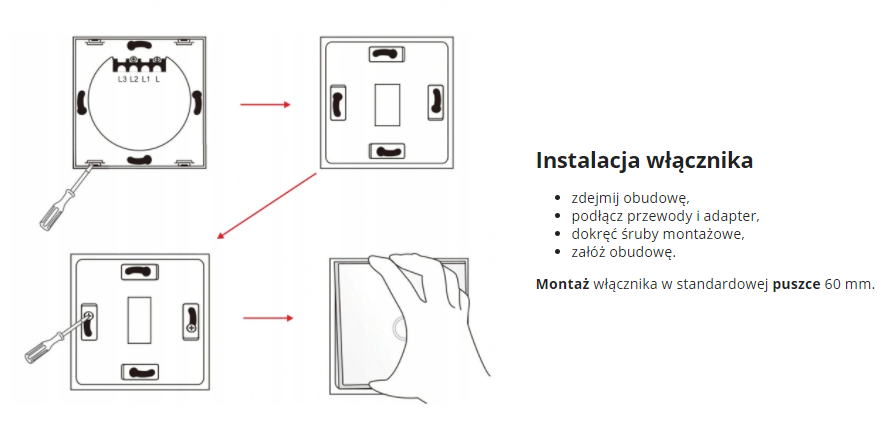
Installation instructions from the seller:
 .
.
Most interesting, however, is its electrical connection:
 .
.
Unlike the ones I have tested before, the switch does not require the N wire to be connected, it just plugs into the L. The mysterious 'adapter' in the graphic above is obviously a capacitor (I don't know why the seller calls it that), but details later.
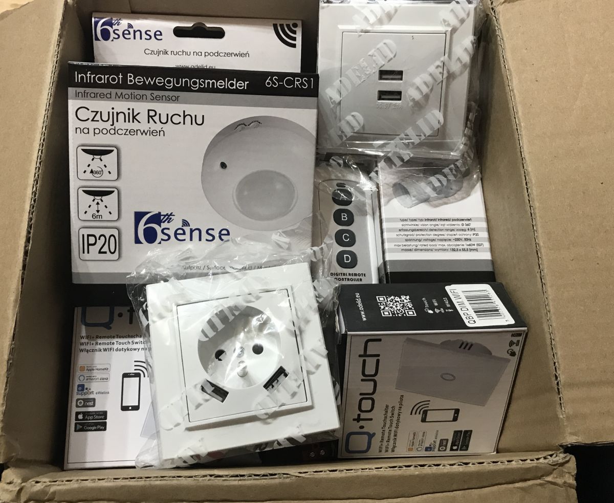
The contents of the kit, first impression .
There was no problem with shipping, as I ordered from Poland. In addition to this switch I bought several other things, the whole set came:
 .
.
The protagonist of the subject was in a sturdy hard cardboard box:
 .
.
On the packaging is a QR code to download the app:
 .
.
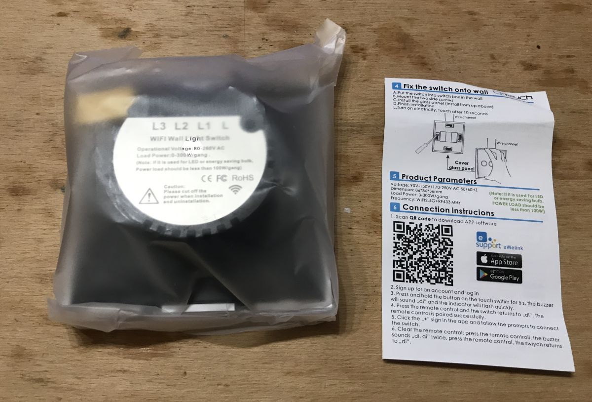
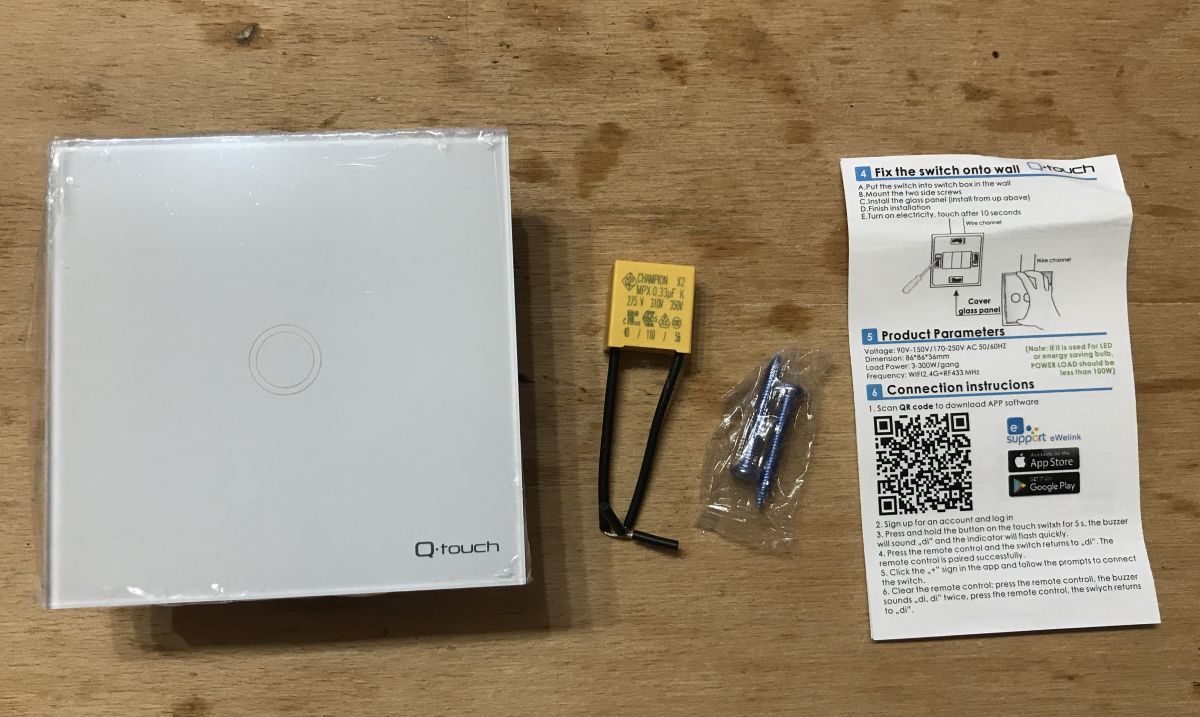
Kit contents:
 .
.
 .
.
Instructions:
MPX 0.33uF CHAMPION X2 capacitor, so called by the seller "adapter":
 .
.
That's what you get in the kit, there are also two fixing screws, that's a nice addition too. Time to test how it works.
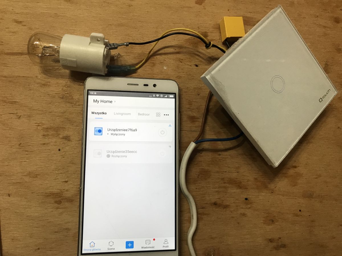
First run .
I connected everything as shown in the photo, the 'adapter' in parallel with the bulb.
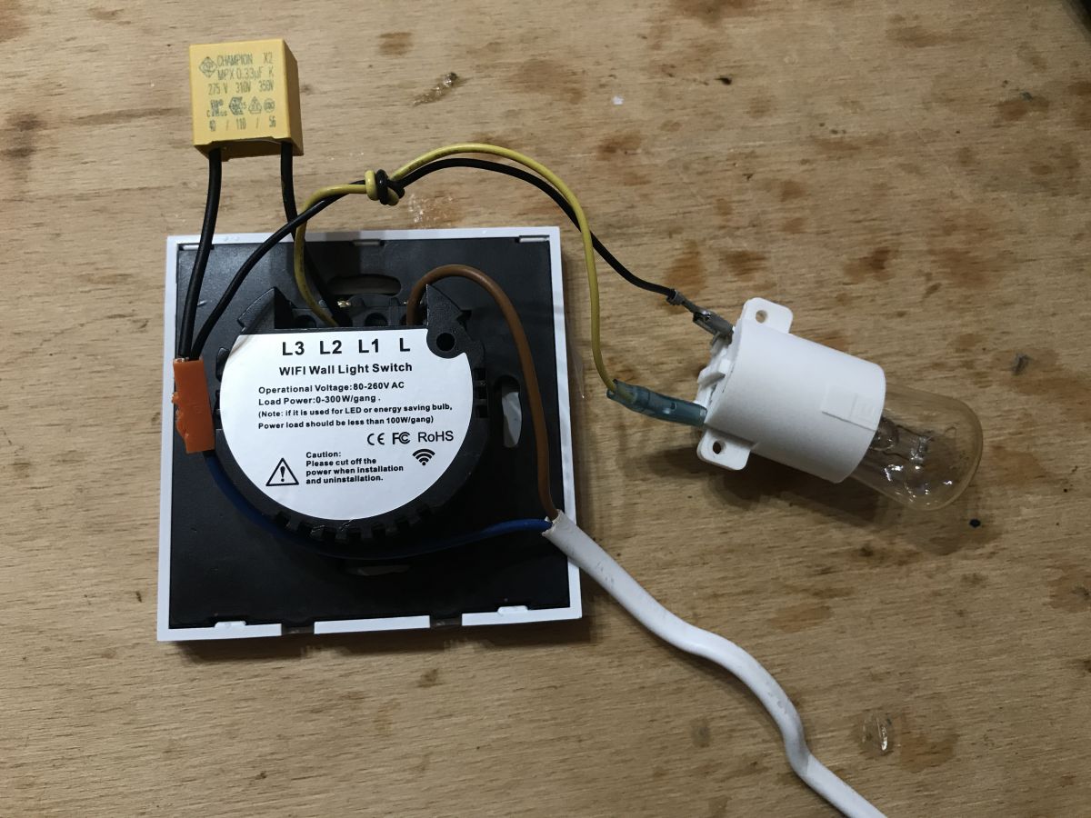
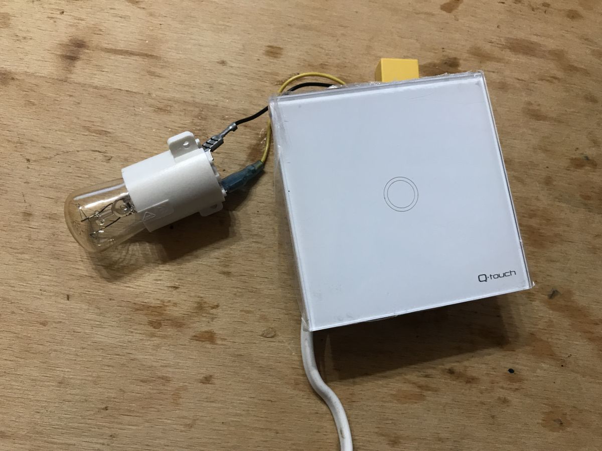 .
.
("adapter" can be at the lamp near the ceiling, it does not have to be in the box next to the switch, anyway the whole idea of this switch is that if someone does not have N in the box they can use it)
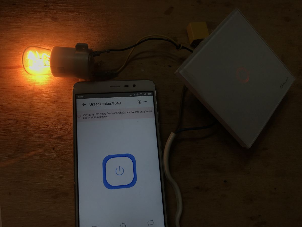
The button reacts to touch:
 .
.
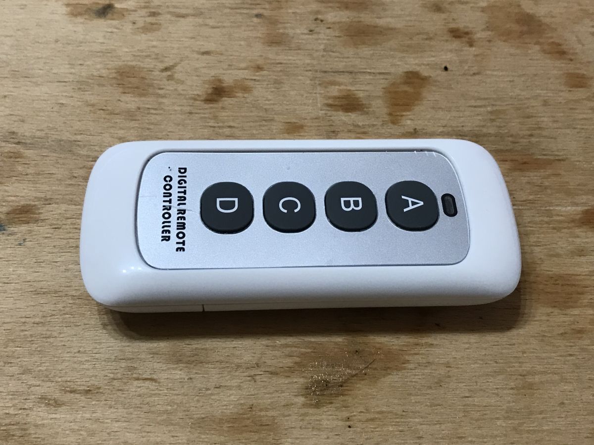
Pairing with RF433 remote .
The RF remote control is a nice bonus quite independent of WiFi. The remote is programmable, it can learn the codes of four different switches.
You can of course also have two remotes paired to one switch, or one remote for each household member.
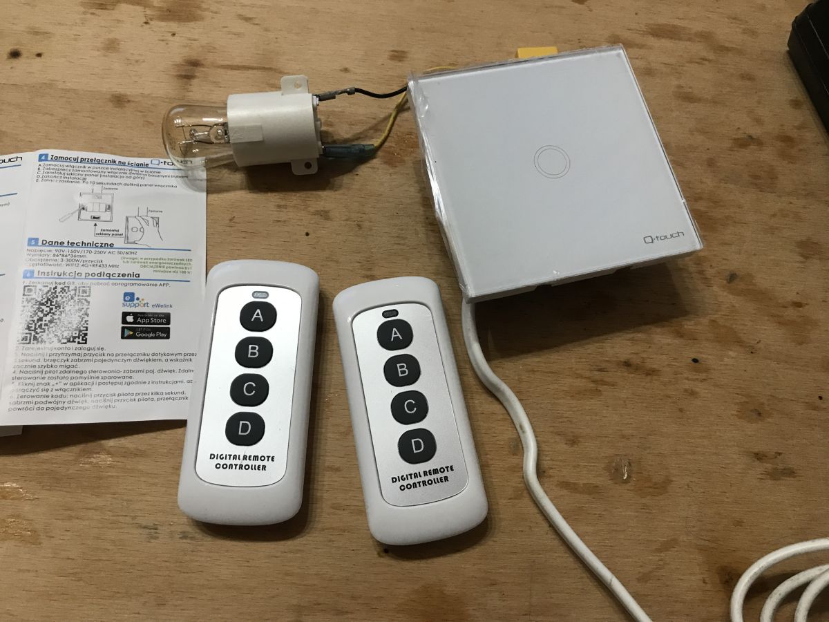 .
.
Pairing is very simple - hold down the touch button on the light switch until it beeps, then press the button on the remote control. Done.
A test of two remote controls:
Everything works, it's already comfortable, and we haven't started the WiFi topic yet.
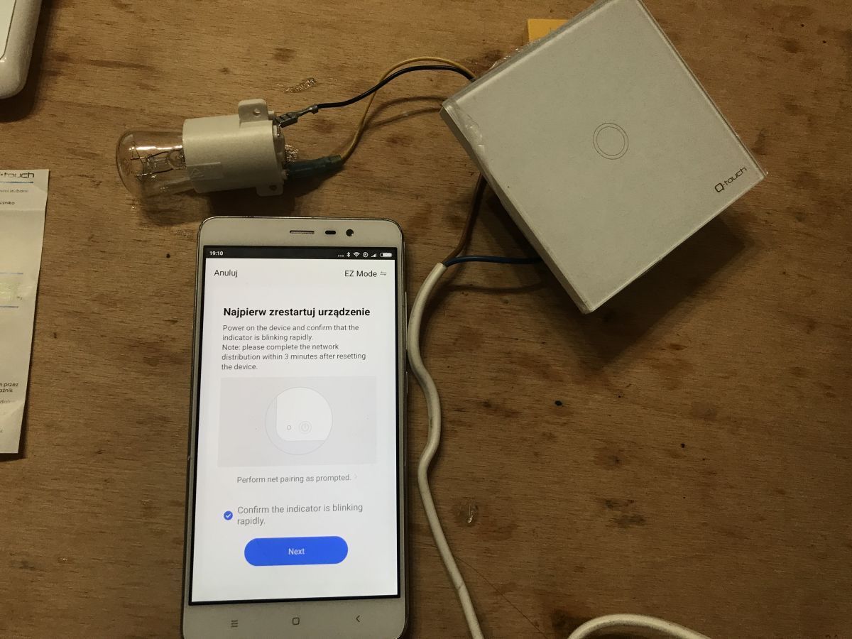
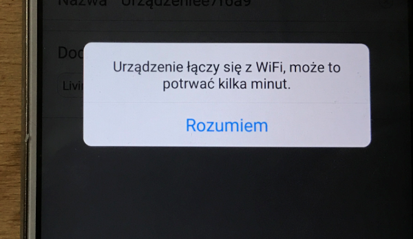
Pairing with the phone app via WiFi .
I have described the eWeLink app and similar ones on several occasions. Here I will just write that after installing the app you enter pairing (normal mode) and reset the switch:
 .
.
After confirming "Confirm the indicator is blinking rapidly" you click "Next" and The phone searches for the device:
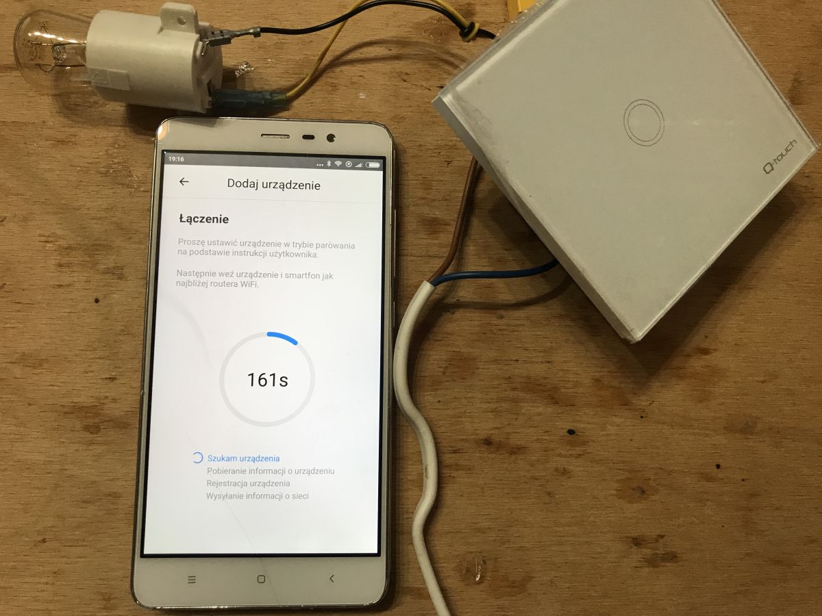 .
.
 .
.
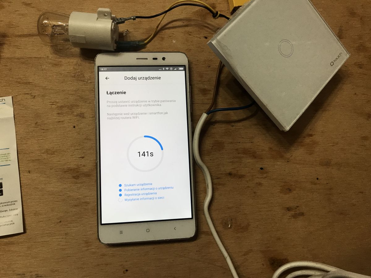
After a while it is found:
 .
.
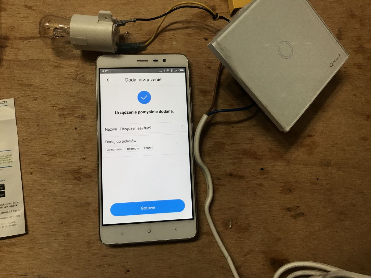
After pairing you have to wait a few moments:
 .
.
and from that moment the device is in the list (you can assign it to rooms, create automations):
 .
.
And, of course, turn the lights on remotely:
 .
.
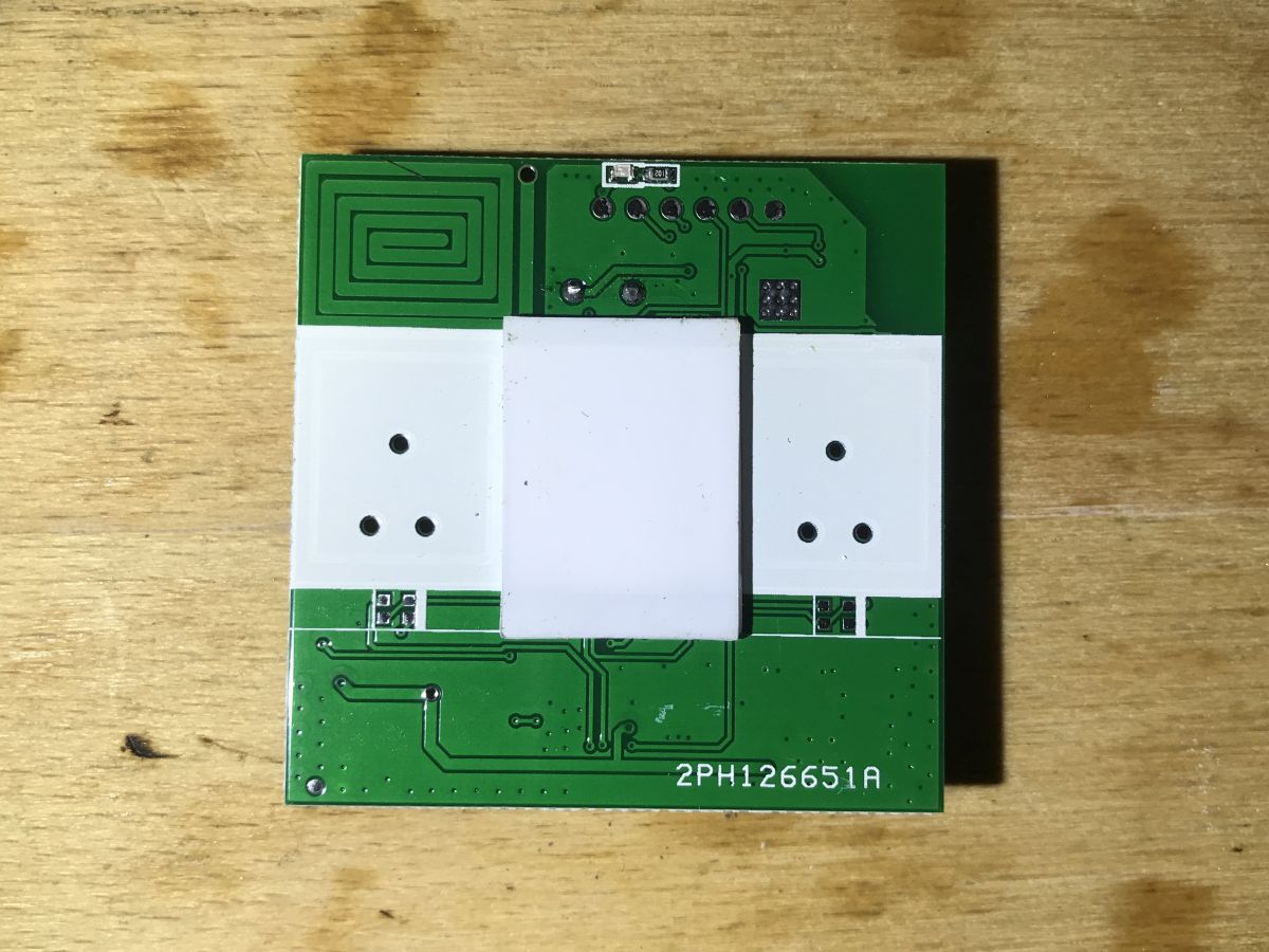
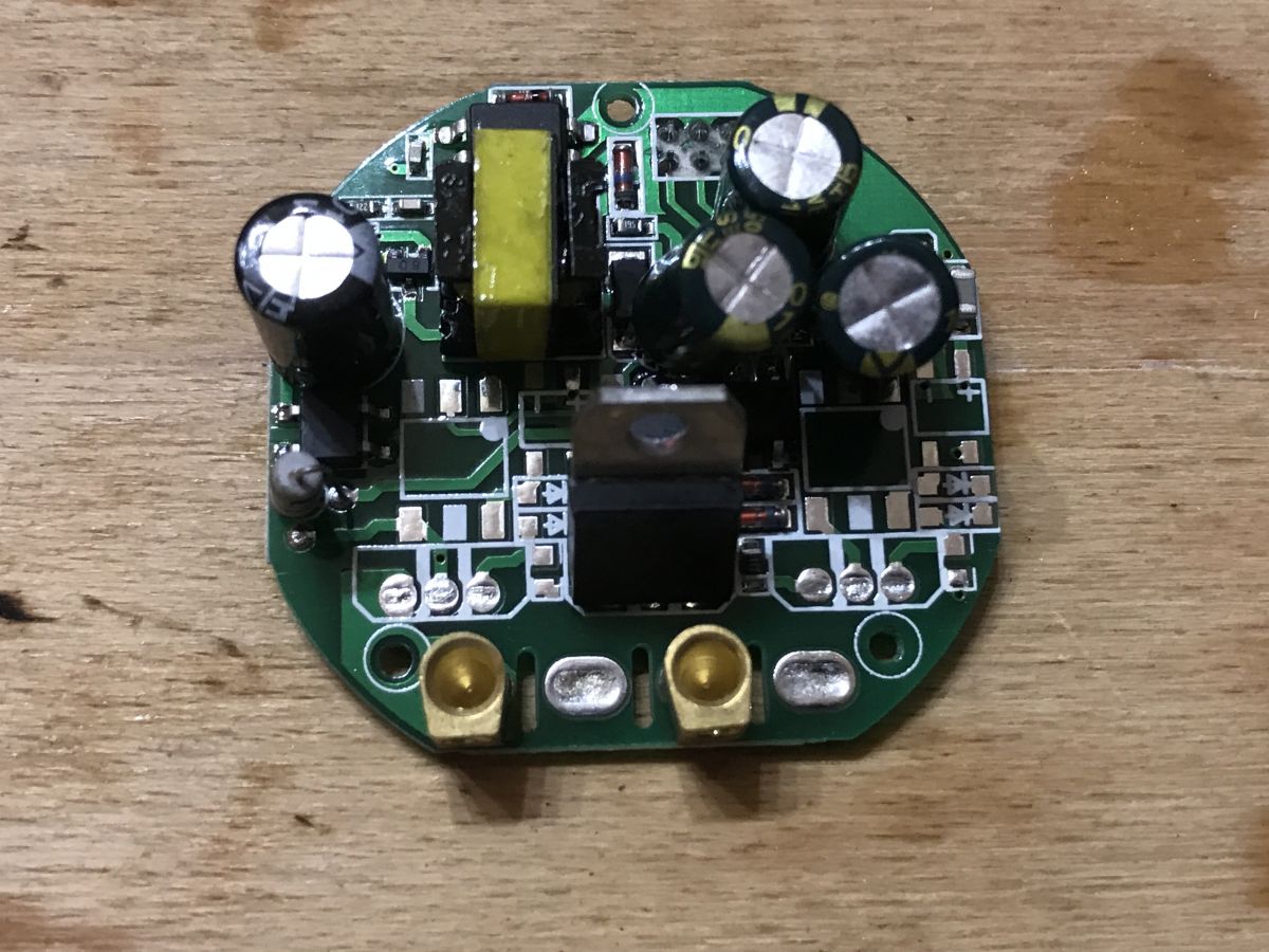
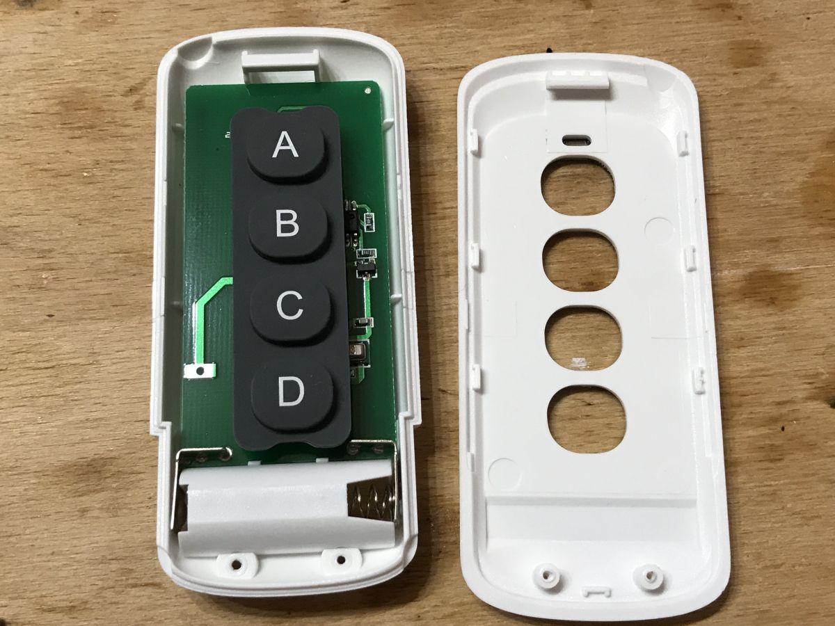
Teardown .
Now it's time to look inside, to determine what WiFi module is at the heart of the product and whether you can possibly upload your own firmware to it.
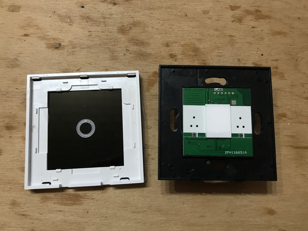
The front panel is held on by clips, undermined with a screwdriver:
 .
.
There are two plates inside. The first one can be easily removed:
 .
.
We will look at each of them.
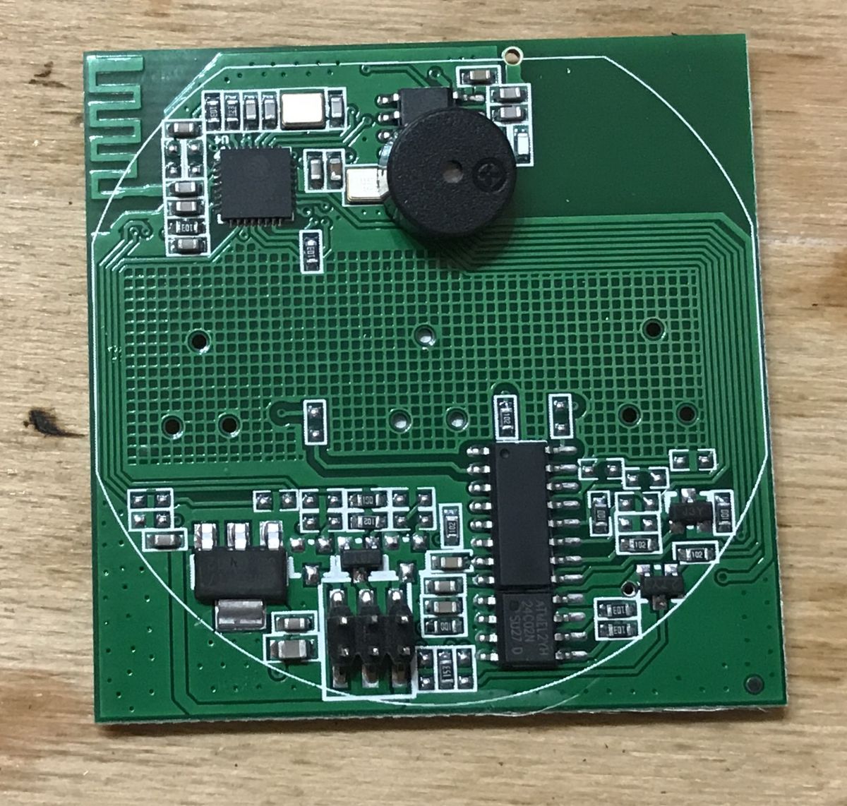
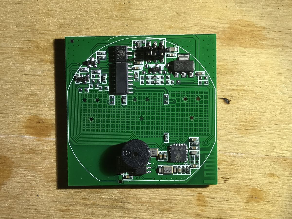
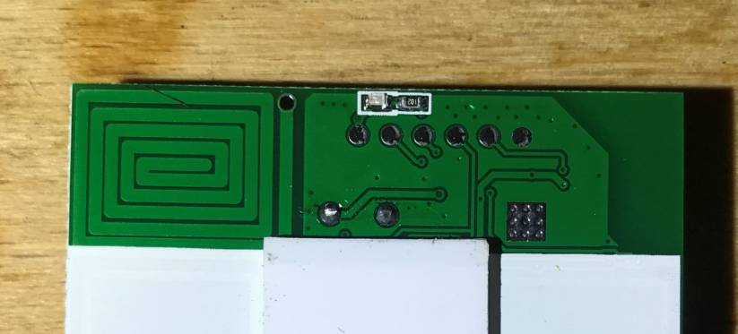
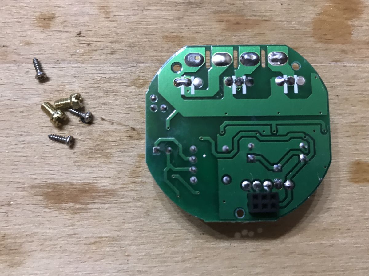
The WiFi board .
The first board contains circuits powered by a low voltage, about 5V from the second board.
Here we see the touch button and space for two more (all three versions of the switch use the same board):
 .
.
In the photo above you can see one antenna on the PCB (from the track).
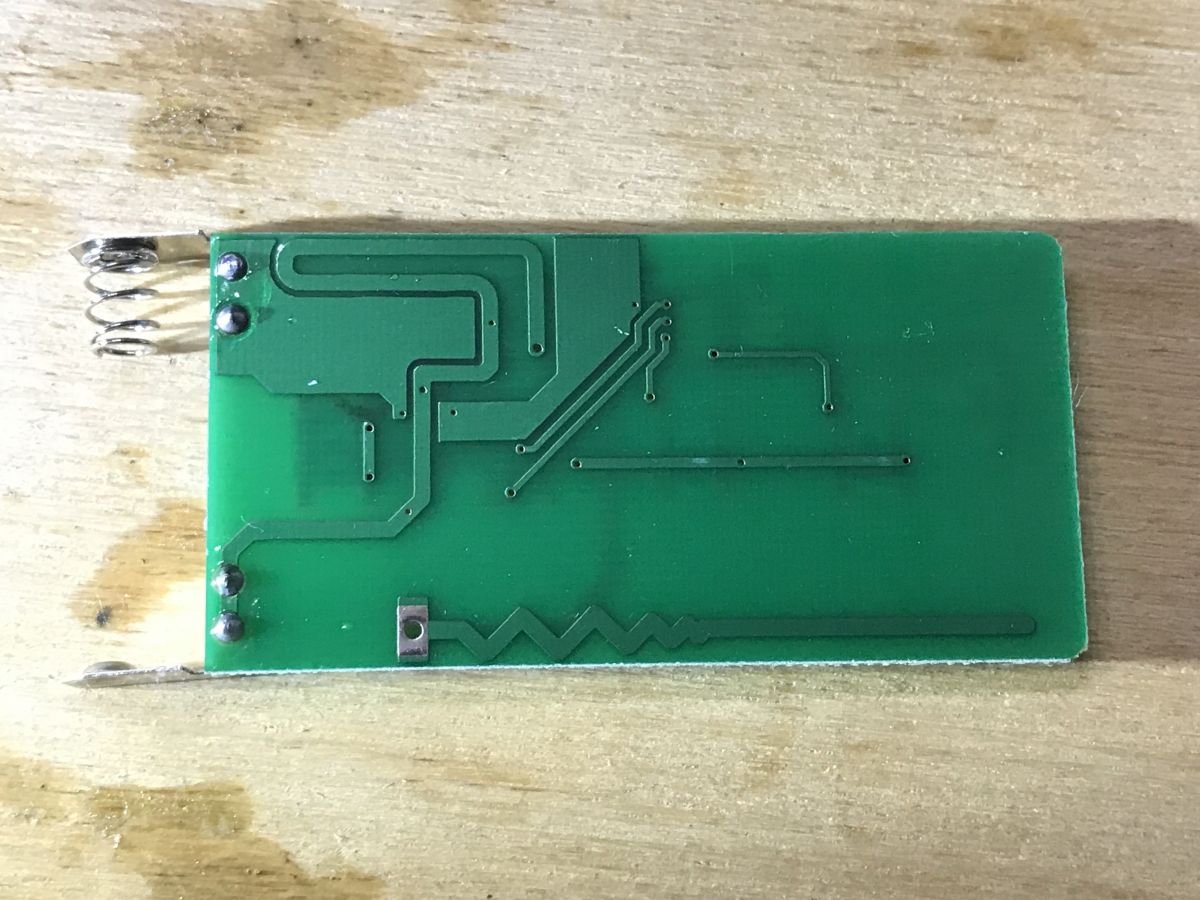
The underside of the board:
 .
.
 .
.
You can see here the second antenna on the PCB, also from the path. One antenna is from WiFi, the other from RF433.
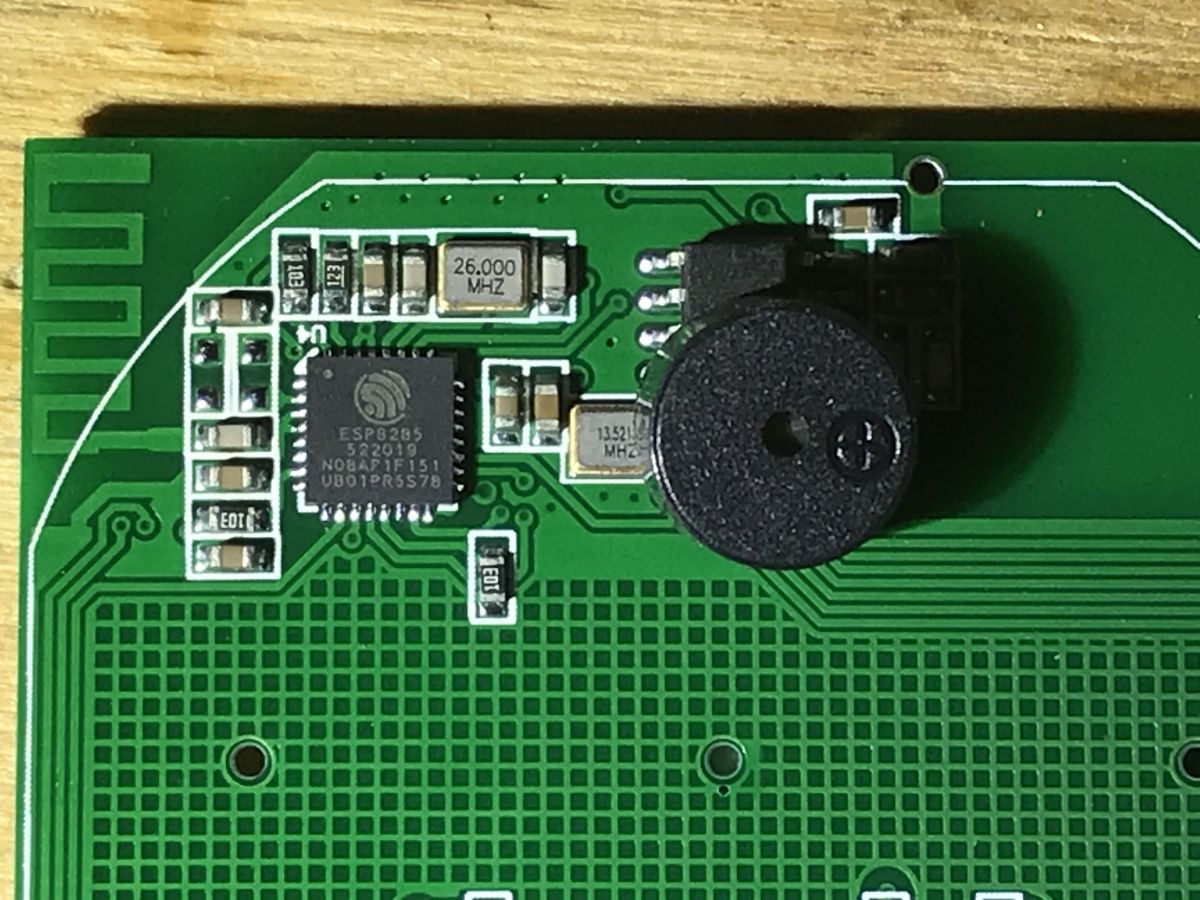
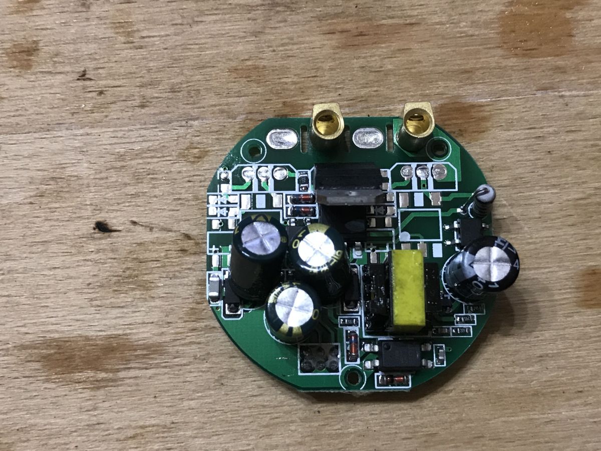
You can see the main microcontroller and WiFi chip at the same time - the famous ESP8285 along with the 26MHz quartz resonator:
 .
.
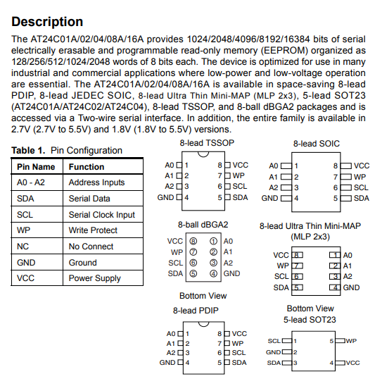
The ESP8285 is essentially an ESP8266 but with integrated 1MB Flash memory in DOUT mode. So while normally with the ESP8266 we have a separate Flash bone, here everything is in one housing.
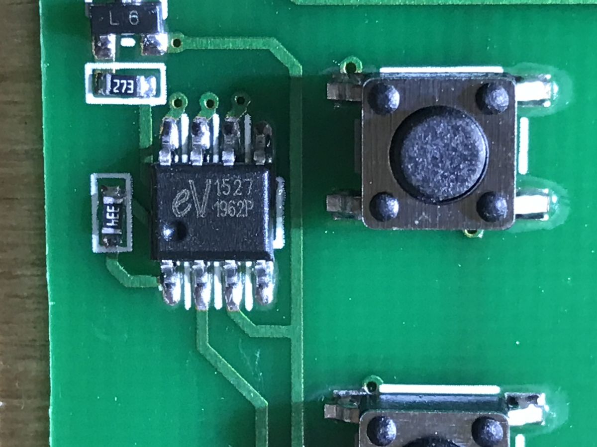
So you can easily upload your own batch and program this chip.
Next to it, we see a buzzer and an IC in SOIC/SSOP from RF433 (the buzzer gives a signal when we pair the switch with the remote control). I've analysed a similar circuit before, and as far as I know the circuit from RF433 is connected to the ESP lead that goes to the touch button. The RF433 chip observes if the button is pressed for a long time and then activates the pairing mode. The RF433 chip also responds to the remote control, in which case it short-circuits the aforementioned line to ground and simulates the touch button press itself in this way.
So basically, the ESP8266 (or 8285) "does not know" that it is working with the RF433 chip. A very convenient solution.
Now let's take a look at this section:
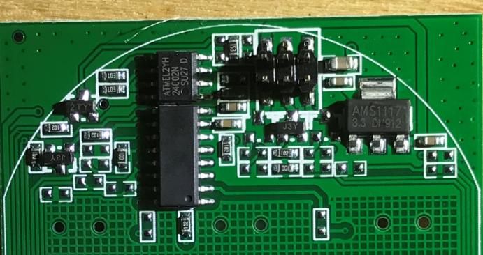 .
.
Here is first of all the LDO AMS1117 3.3V regulator, it provides a stable 3.3V for the rest of the circuit. There is probably some 5V going to this board from the other module. There is a large chip (unsigned) that handles the touch buttons, and there is an ATMEL2YH 24C02N memory die:
 .
.
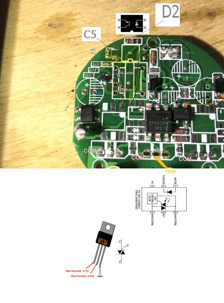
We also have transistors there (J3Y, or S8050), which are used to switch the light on/off, but this time not via a relay but via a triac (but more on that later).
There is also a connector for programming:
 .
.
Programming and Tasmota .
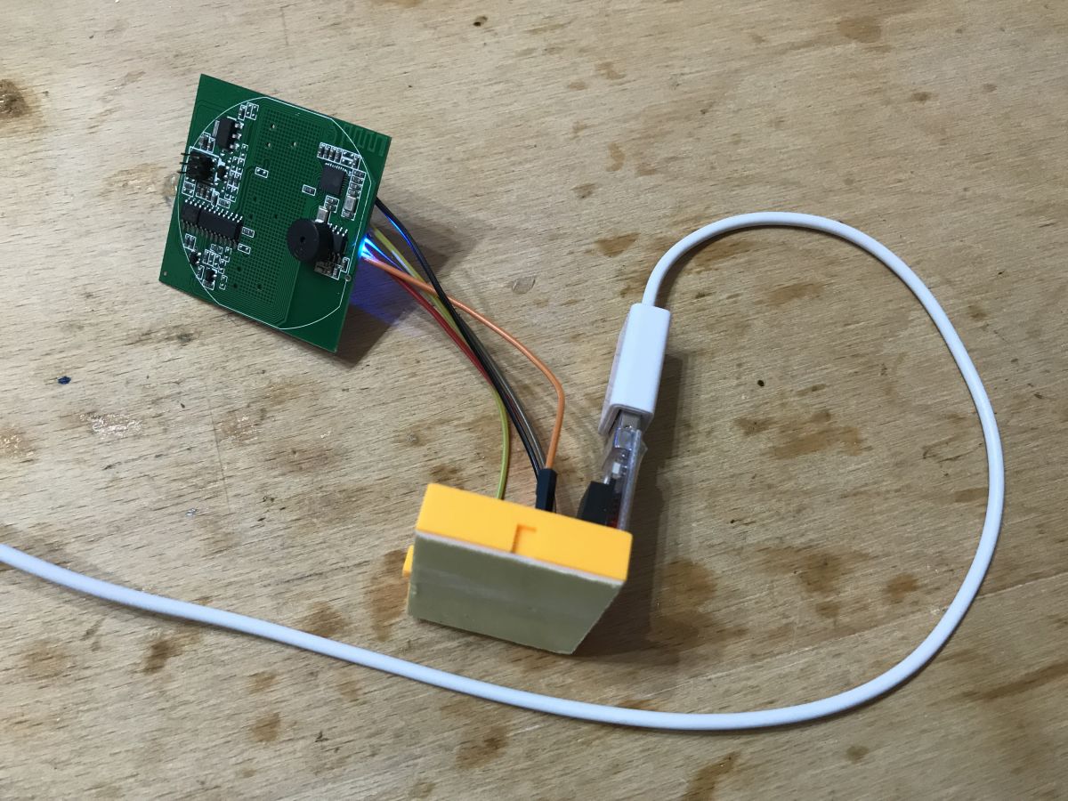
Now we will try to upload Tasmota, the open source software for this type of switch, onto this ESP.
I have traced the pin connections:
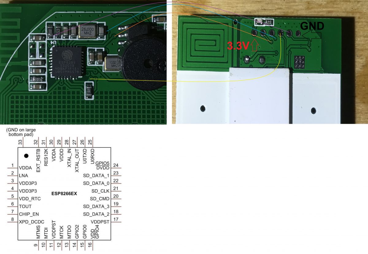 .
.
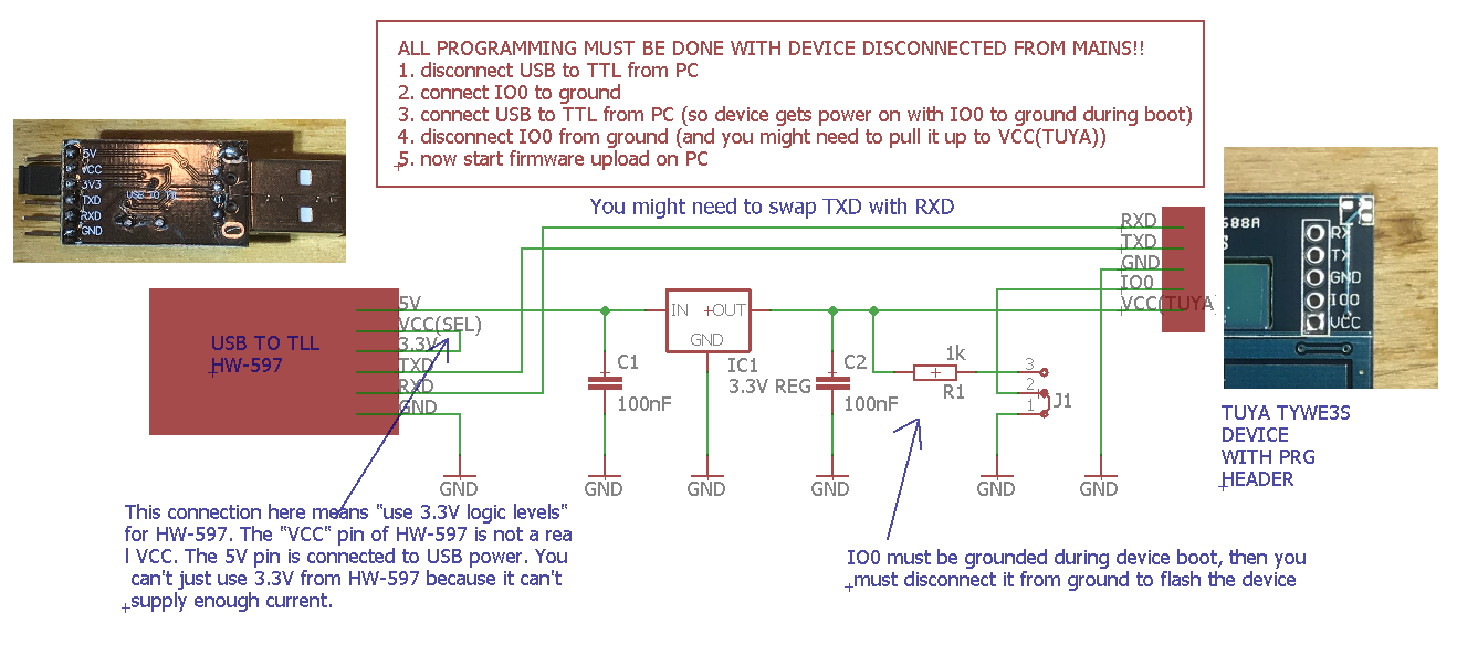
Before any operation on the switch, disconnect it from the mains!!! .
Programming is done here via the UART, according to this diagram which I have already drawn on the forum some time ago:
 .
.
(you will find details of the programming in related topics in this series)
 .
.
 .
.
 .
.
On the computer side, I used the python script esptool.py which I installed with the ESP8266 support package for Arduino.
The command esptool.py chip_id to check if the programmer can see the ESP:
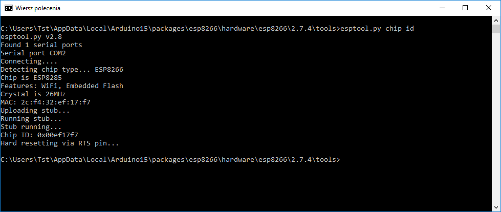 .
.
Command esptool.py read_flash 0x00000000 0x100000 QTouch-20210105.bin to rip the current batch from the ESP to the computer (backup):
 .
.
But at first I had a problem there, there was an error 'Failed to write to target RAM (result was 0107) and the solution was to unplug the GPIO from ground:
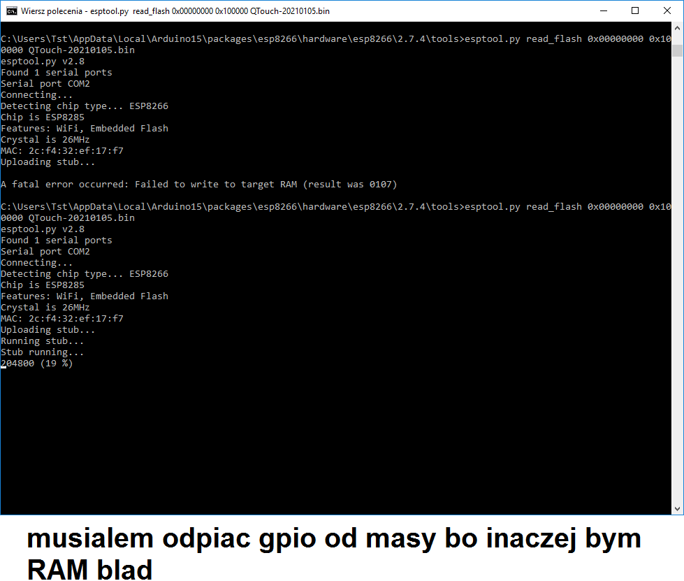 .
.
Command esptool.py write_flash 0x0 tasmota.bin to upload the Tasmota batch:
 .
.
Firmware uploaded. Then the standard (described in previous topics in the series) procedure, Access Point Tasmota:
 .
.
And a pleasant surprise - everything works straight away:
 .
.
Pin configuration (D6 - relay, D7 - LED, D3 - button):
 .
.
Everything works and at this stage I will finish playing with Tasmota for this device. Of course you can then connect Home Assistant, MQTT, but that is beyond the scope of this topic.
I'll still just point out that of course the RF remote continues to work after the firmware change (for reasons discussed earlier), by the way, take a look:
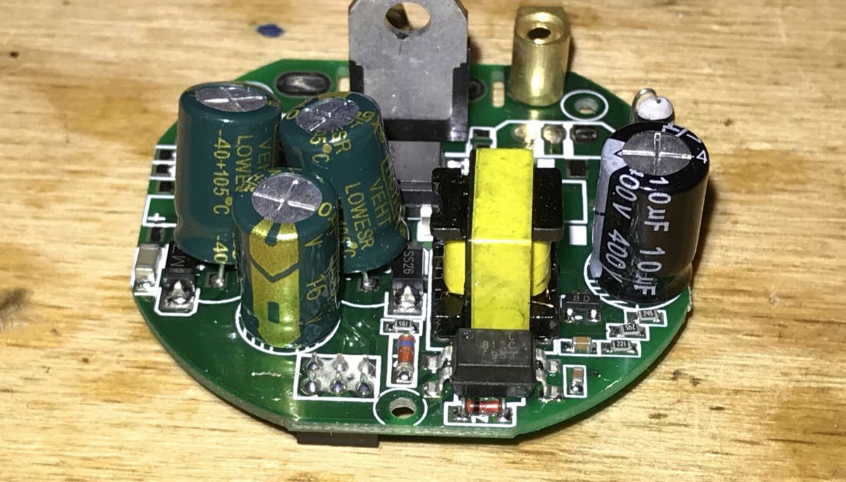
Look at the second board .
Finally, the most interesting part. We'll take a look at the second board from the device, the one that is connected to the network, and try to understand how it all works.
To start with - pictures:
 .
.
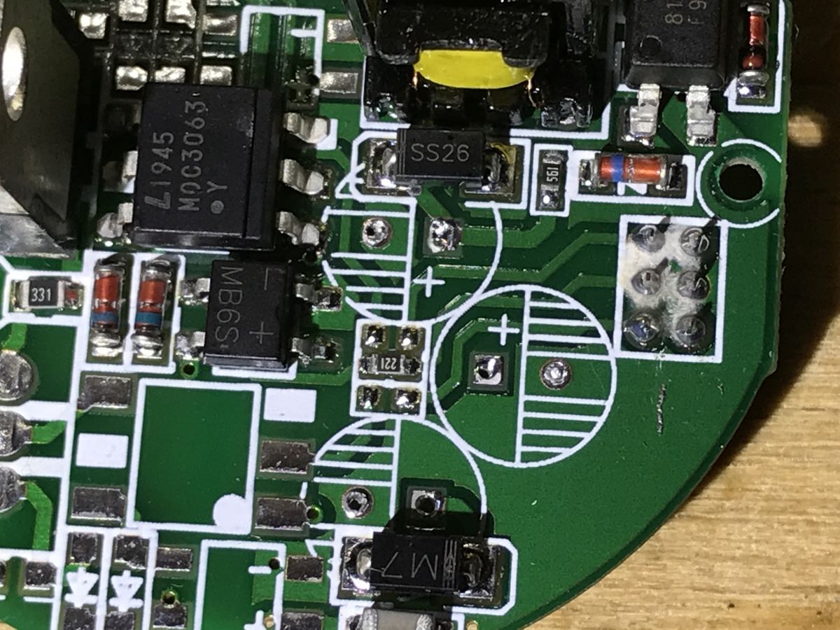
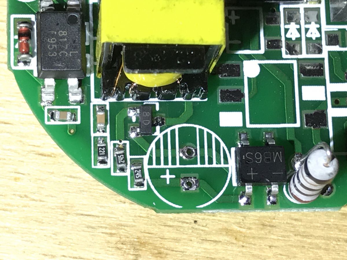
817C, PC817C, optocoupler, schottky SS26 in background:
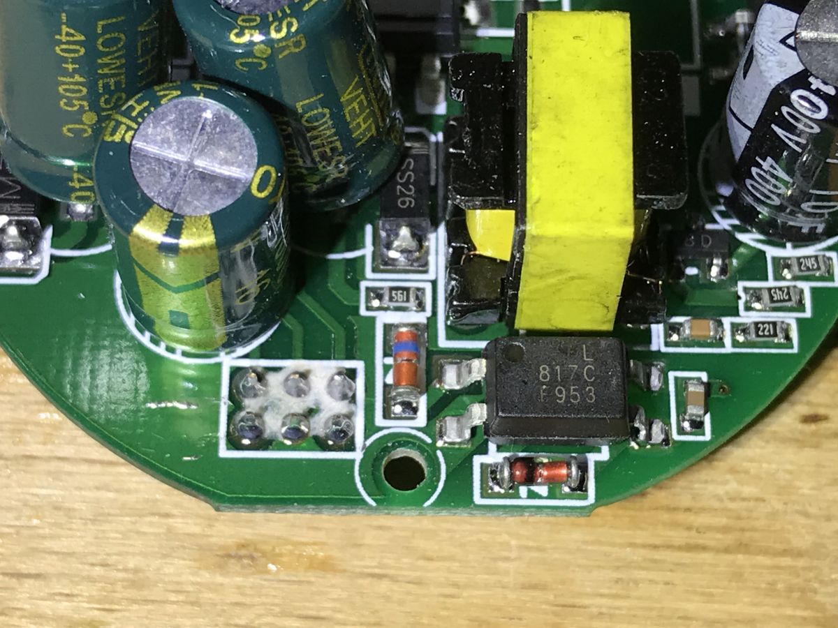 .
.
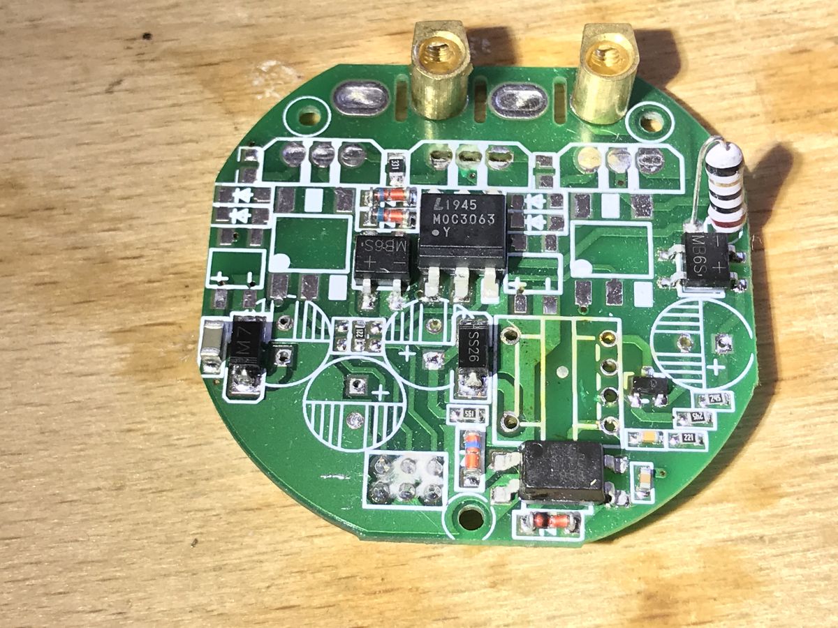
MB6S rectifier bridge, BTA16-600B triac:
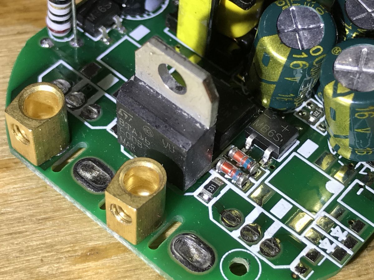 .
.
Yes, this circuit is realised on a triac! Zero relays. This is a big change from what I previously reviewed.
The triac used is a BT16-600B:
 .
.
It is controlled by a MOC3063 optotriac:
 .
.
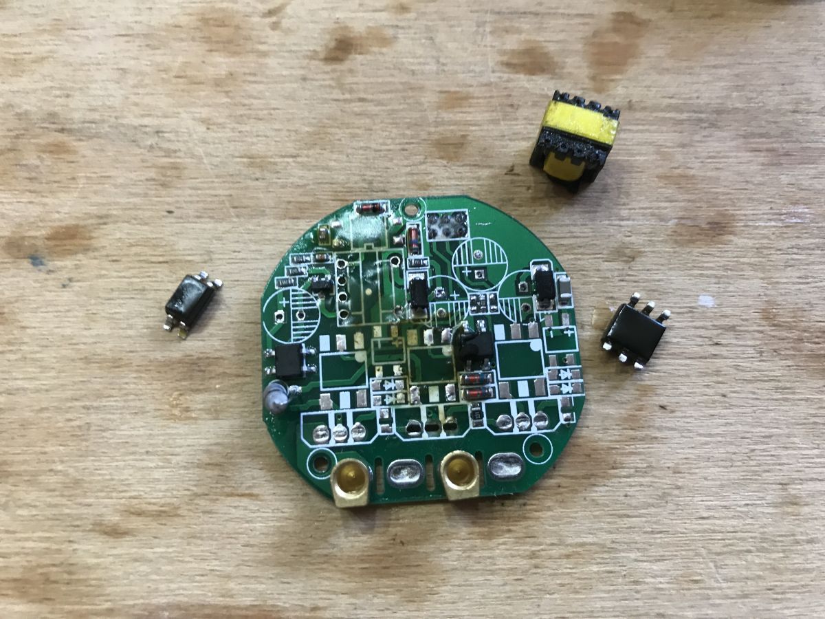
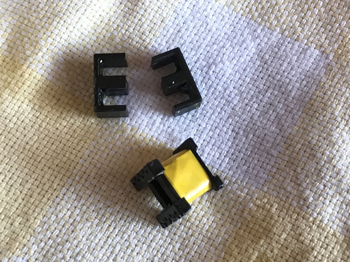
Unfortunately at first glance it can be difficult to tell how it works, so I took the liberty of soldering out some of the components:
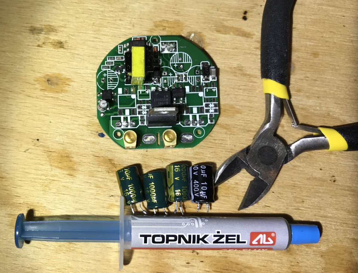
By the way, three capacitors of 1000uF each? That much? That will become clear later.
Soldered out:
 .
.
Close-ups:
 .
.
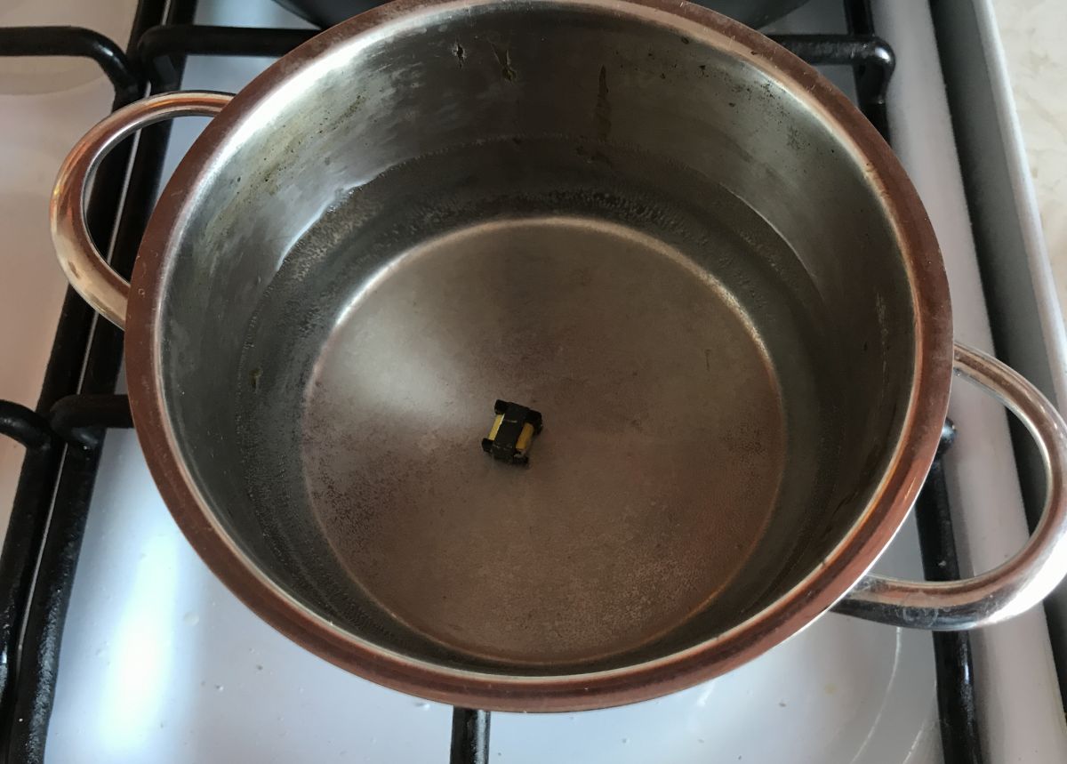
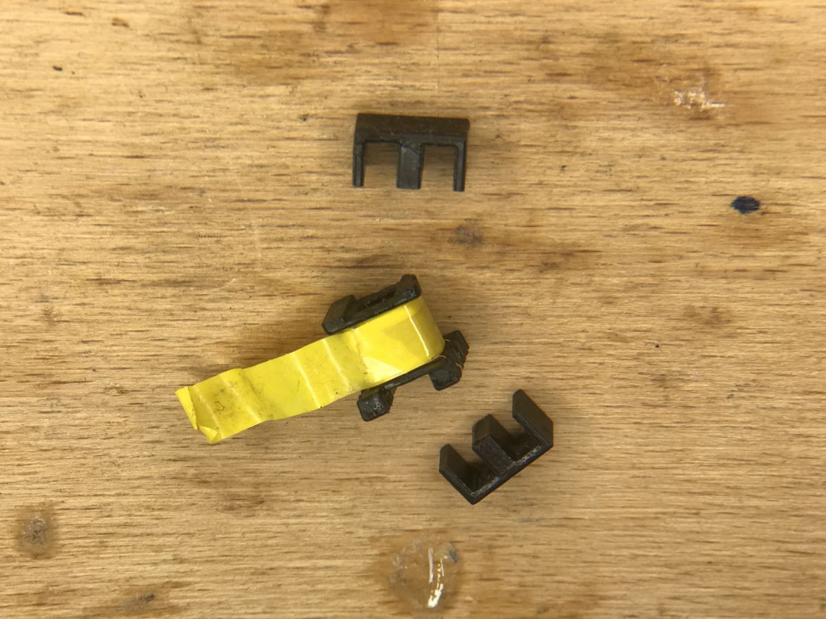
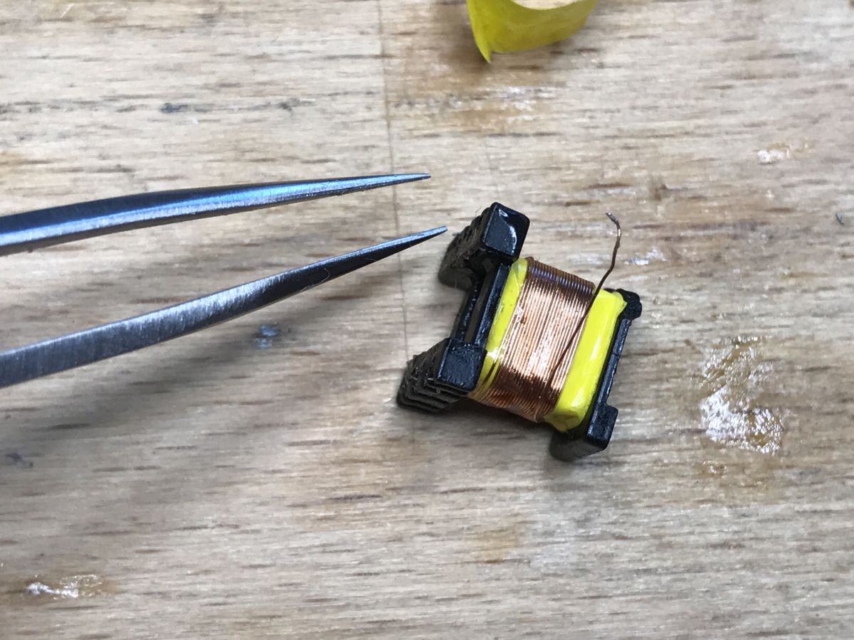
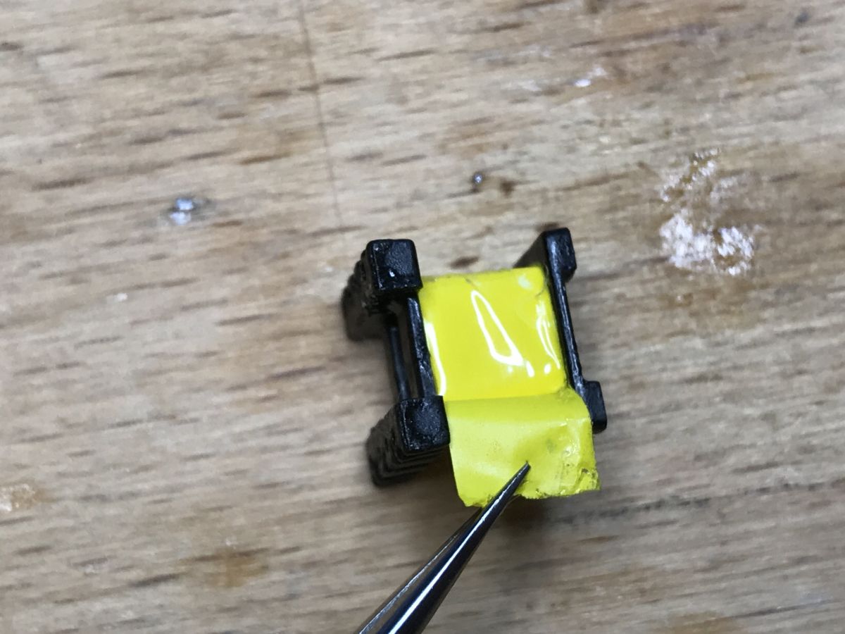
In the end it wasn't enough for me anyway, I was interested in the transformer So I also soldered it out and dissected it:
 .
.
Soldering out additional components to trace the paths:
 .
.
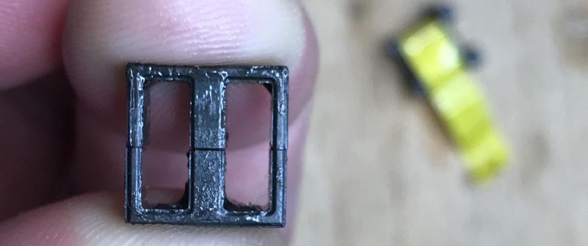
The transformer is generally difficult to open, it is glued together. My way of doing this is to boil it, gradually heating it in water. This helps to remove the glue:
 .
.
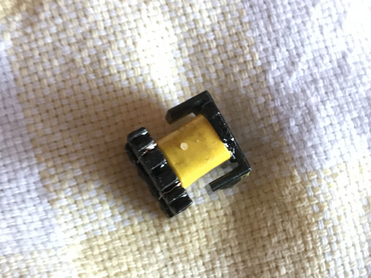
Transformer section:
 .
.
I don't see that it has a core break:
 .
.
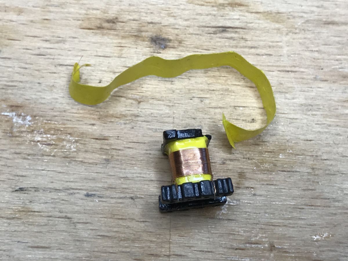
Unwinding:
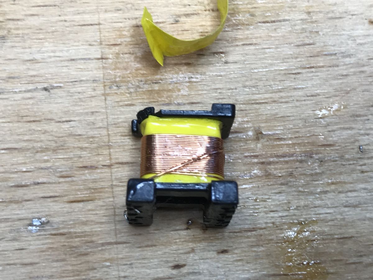
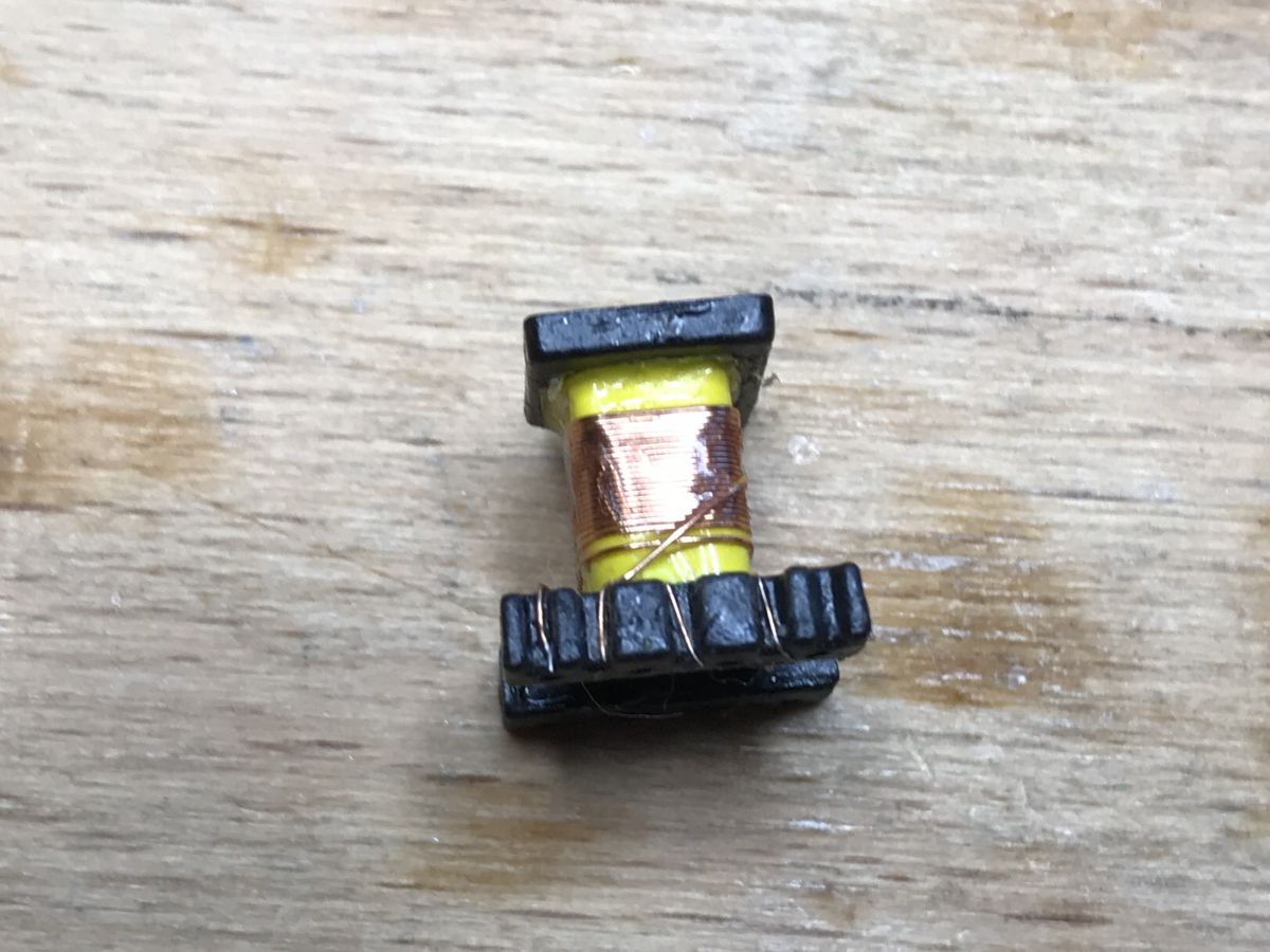
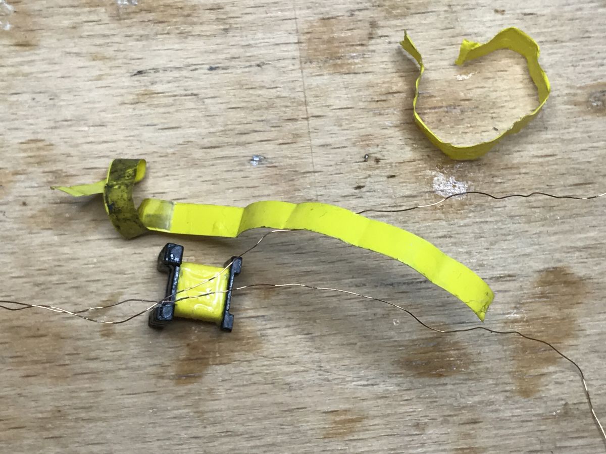
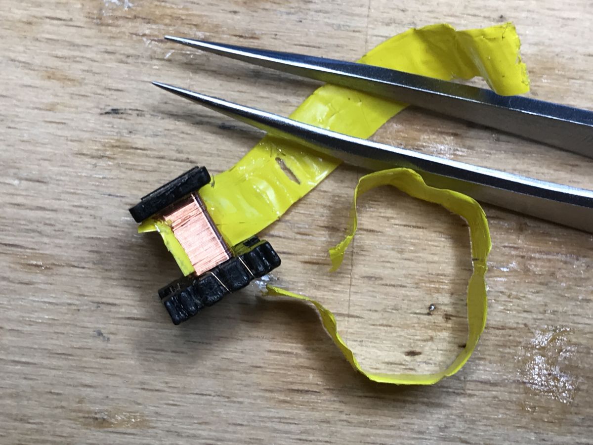
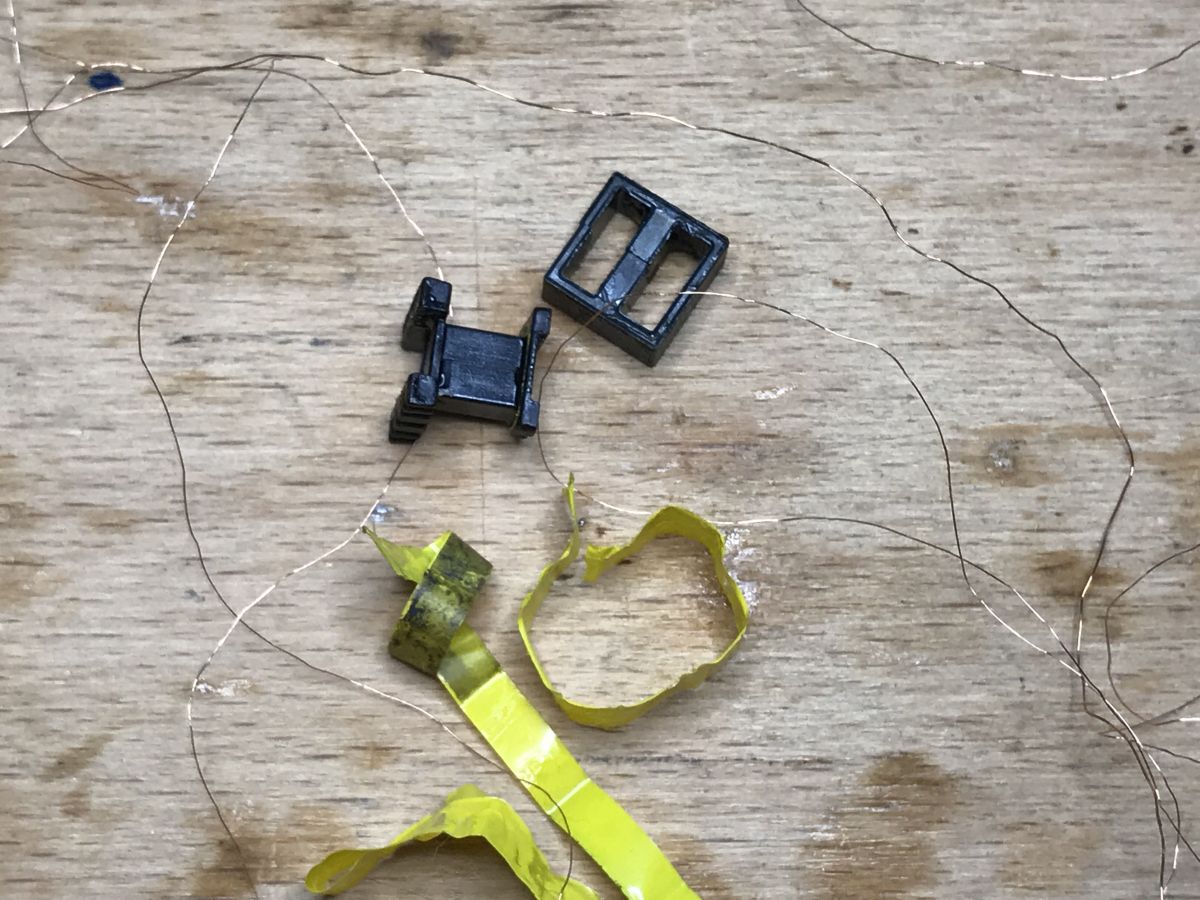 .
.
The number of windings and their configuration I counted and wrote down.
The primary winding 174 windings, the other two 22 windings each.
Schematic of the second board .
Eventually I managed to draw a schematic of the circuit. I also helped myself by describing the board in pictures:
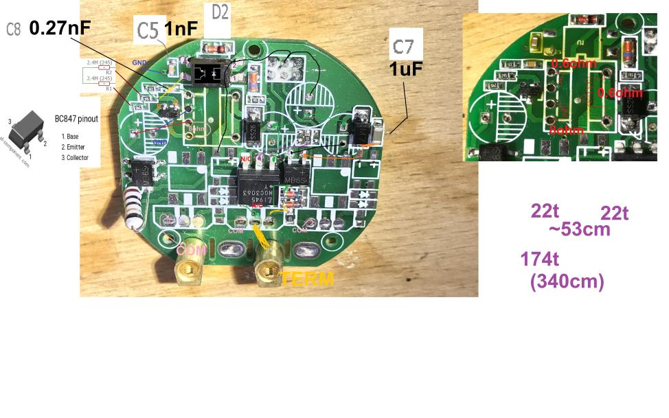 .
.
 .
.
And the result of the work - the schematic (the schematic also shows the "adapter" and the bulb, there is no board from WiFi because we know how it works):
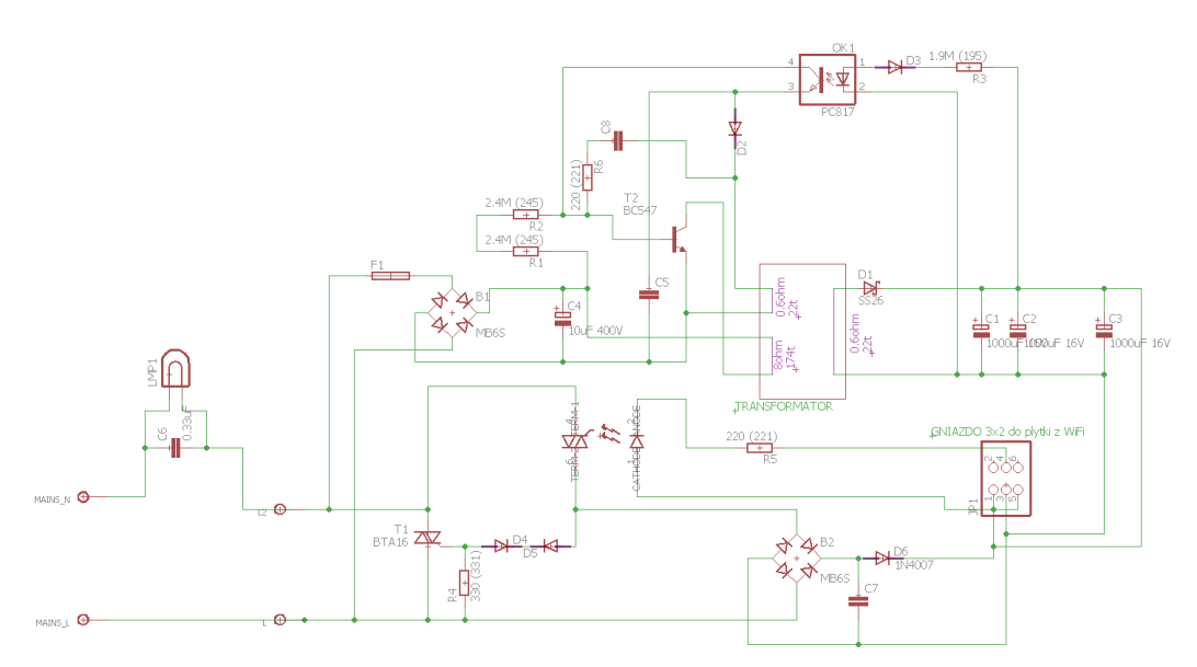 .
.
In my opinion it works more or less like this (if anyone has anything to add, feel free).
There are two modes of operation.
The "lights out" mode - then the circuit feeds the top power supply, this flyback with transformer, realised on a single small transistor in a SOT-23 case with SMD code 8D (in the schematic it is BC547, but this is MJE13001, 0.2A/400V) with coupling on a PC817 optocoupler. It can only work because very little current flows through the circuit (through the 'adapter' and the bulb), this power supply connected normally to the mains would not work. This power supply charges electrolytic capacitors, there are as many as 3 x 1000uF, this is indeed a lot, but for good reason. This allows the WiFi module to work and turn on the triac if it needs to.
Mode "light on" - this is when the ESP8285, via the transistor and MOC3063, turns on the triac, i.e. short-circuits the inputs of the "top" power supply circuit. The triac must be constantly on, because when the current drops it shuts down (I assume the reader knows how the triac works). The top power supply stops working, but the circuit continues to be powered because we also have a 'bottom power supply'. This bottom power supply is just a rectifier bridge, a 1N4007 diode and immediately behind it there are already capacitors for 16V. This is because the BTA16 triac is switched on here with some delay, but the delay is not the responsibility of the ESP, the ESP "doesn't know" about the delay, but the components behind the MOC3063, these two diodes connected by cathodes, probably Zener diodes. The voltage from the mains is, of course, a sine wave, and the triac switches on a moment after the start of the rise cycle, when the voltage only reaches a few volts (that is, the breakdown voltage of the Zener diodes connected by cathodes). And for this short start of the cycle when the triac is off (but the MOC3063 is conducting), the lower power supply charges the capacitors with this low voltage (that's why there are as many as 3000uF), and then the triac turns on and lights the lamp (the lamp doesn't feel that it has cut a short part of the cycle from the sine wave).
Those 3000uF are there to provide the module from WiFi with continuous power, even though the capacitors themselves are charged a little at a time.
In my opinion, this is how the circuit works, if someone has something to add then feel free to do so, the top power supply could also be discussed in more detail (the number of windings is marked, there is a third winding in addition to the primary and secondary windings), but this is no longer relevant to the idea of the circuit itself.
Catalogue notes of the more interesting components:
.
.
Additional - RF433 remote control interior .
Still, let's take a look at what kind of RF433 remotes this seller had (there are different ones in circulation):
 .
.
The remote control is powered by a 27A 12V battery:
 .
.
Interior:
 .
.
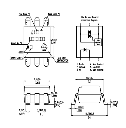
The pilot is realised on an EV1527 1962P:
 .
.
It is an OTP chip manufactured by Sunrom using CMOS technology:
 .
.
There is a diagram of an example application in its catalogue note:
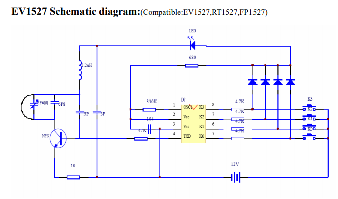 .
.
Full note:
.
Summary .
The qTouch switch works with the eWeLink app, but can also be used with Tasmota and Home Assistant. Inside sits an ESP8285, which can be easily programmed.
This switch can be easily paired with several RF remotes so that each household member has their own remote. The RF remotes work even after changing the firmware on the ESP8285 to your own.
On the switching side, the qTouch switch is done unusually, as it is on a triac rather than a relay. I drew the schematic and posted it earlier.
The switch is also distinctive in that it simply plugs into the L line (in series with the bulb) and this can be useful when you don't have an N in the box, although there is no such situation at my house.
Have any of you perhaps used this type of WiFi switch and indeed do not have the N plugged into the box? .
PS: Of course the triac board has been quite disassembled to take pictures and the transformer section, I don't intend to solder it back, but the parts will come in handy and the WiFi + RF433 board will be used separately, I will give a small 5V power supply, a relay and everything will run with Tasmota.

p.kaczmarek2 wrote 14607 posts with
rating 12622 , helped 654 times.
Been with us since 2014 year.
Comments
Hello Is this transistor definitely a BC547 ?... With a dark bulb this component is practically at full potential around 300V.... The inverter is self-excited, and probably the resistors R1 and R2 are... [Read more]
If I understand correctly, this 'adapter' allows the switch to be powered when the lamps are underpowered. Then this "adapter" allows a certain small capacitive current to flow necessary for the switch... [Read more]
. Thanks for your vigilance. The transistor from this inverter can be seen in the pictures and is code D8. It is not likely to be a BC547 (or thereabouts its surface-mounted equivalent BC847). I'll... [Read more]
. It looks like a colleague is looking for the wrong code, as the 8D is visible in the photo Just out of curiosity, I would also measure this component with a meter directly on the PCB (in the current... [Read more]
No no, the search was ok, just a typo while writing the post just after Easter breakfast . AND it's not a problem as long as I have the pcb to hand: https://obrazki.elektroda.pl/1301645300_1617566122_thumb.jpg... [Read more]
Initial measurements indicate that it is indeed an NPN transistor. Personally, I would take one more measurement in the reverse direction B-E and B-C Anyway, if a colleague finds the time for a more detailed... [Read more]
This measurement was also taken, of course. Now I've finally had time to sit down quietly to do this, and I can say that it's more like a MJE13001 13001 8D 0.2A/400V SOT23. The SMD code agrees. The... [Read more]
The biggest problem I see with equipment from China is that it does not fit P&P into the standard installation boxes used in Poland. Can a colleague share his knowledge as to how in this case? Does... [Read more]
Now it would all add up... The only thing to bear in mind is that such a switch should not be regarded as a guaranteed break in an electrical circuit. Regards. [Read more]
. There is no problem with this. I've bought switches from various manufacturers (you have a list of topic-reviews in the first post) and as far as I can see they are standardised. And if you have concerns,... [Read more]
. Agreed, especially as there is no visible insulation break.... However, the fact is (as long as you establish the absence of voltage) that a classic circuit breaker can be treated as a specified safe... [Read more]
And I thought THEY were ahead, and look at this: in order to make it work, a capacitor is needed to power a 10 W LED bulb, and when it turns on, it only uses the drop on the triac, not stupid at all, but... [Read more]
I think my colleague has a poor appreciation of polish.... [Read more]
I only appreciate myself;. Those. who do not value. Added after 21 [minutes]: . I remember when they switched on the transformer, there were no meters, everyone paid 10 zł for two months when they... [Read more]
eh, silly talk again.... :| https://biznes.interia.pl/gospodarka/news-w-polsce-powstal-najszybszy-jednosilnikowy-odrzutowiec-na-sw,nId,5145326 You have a rather poor idea of what a Pole can come up... [Read more]
Hello, I have 2 single (kitchen and bathroom) and 2 double switches (small room and large room) installed in my flat The switches were bought in 2019. The first double switch broke after initial disassembly... [Read more]
Hello, I also use these Chinese light switches, most of them have similar electronics, I will leave pictures of two of them for your perusal, the remote control is the same but you can also connect another... [Read more]
Hello! An hour ago in a double Qtouch switch I blew a 10u/400V capacitor behind the bridge. The load was two LED lights of 3W on one branch and two LED lights of about 7W on the other, so almost nothing.... [Read more]
400V isn't much of a stick in such a small enclosure. Probably crap quality capacitors, and they're still connected to the power supply, as far as the eye can see he's at the input of the inverter powering... [Read more]