 Hello my dear.
 Here I will test a WiFi driver / dimmer for a single-color LED strip compatible with the SmartLife application. Then I will show its interior and sketch its diagram. I will also check how high the currents it can withstand and repair a minor defect that will arise as a result of my tests.
Related Topics I have already written a few topics about ESP-based WiFi products. I mainly show interiors there.
I also describe the process of programming such a switch there and using it with the manufacturer's application (Blitzwolf, SmartLife, Tuya, eWeLink) or Tasmota.
I recommend that you familiarize yourself with these topics, I will not repeat all the information several times and as a rule, they apply to all products of this type.
List below:
-
BW-LT30, i.e. a WiFi adapter for a light bulb - test, teardown and uploading ESP firmware -
WiFi-controlled electrical socket - BW-SHP8 - start-up and tests -
Test and interior of the BW-SS3, i.e. the WiFi light switch from Blitzwolf -
PS-16-M WiFi socket / plug and eWeLink / Coolkit application - test and teardown -
SmartLife switch - test, interior and WiFi light switch programming (similar switch, but without RF and description of programming it in Arduino via cables)
-
SC3-01 SmartLife switch and uploading ESP firmware via WIFI (tuya-convert / OTA) (this time programming via WiFi, no need to open the housing, no soldering of cables)
-
WiFi QTouch switch can only be plugged into the L cable - test, interior, diagram Additionally, a second topic about Tasmota:
-
ESP8266 and Tasmota - step-by-step control of the WiFi relay Additionally, I recommend the topic about Home Assistant (which can control a collection of such devices):
Home Assistant Tutorial - configuration, WiFi, MQTT, Zigbee, Tasmota In some of the topics above, I also discuss the possibility of creating automation for devices of this type (eg rules such as "automatically turn on the lighting when it is after 10 p.m.", or "turn on the lighting when the motion sensor detects the presence of a person in the room", etc.).
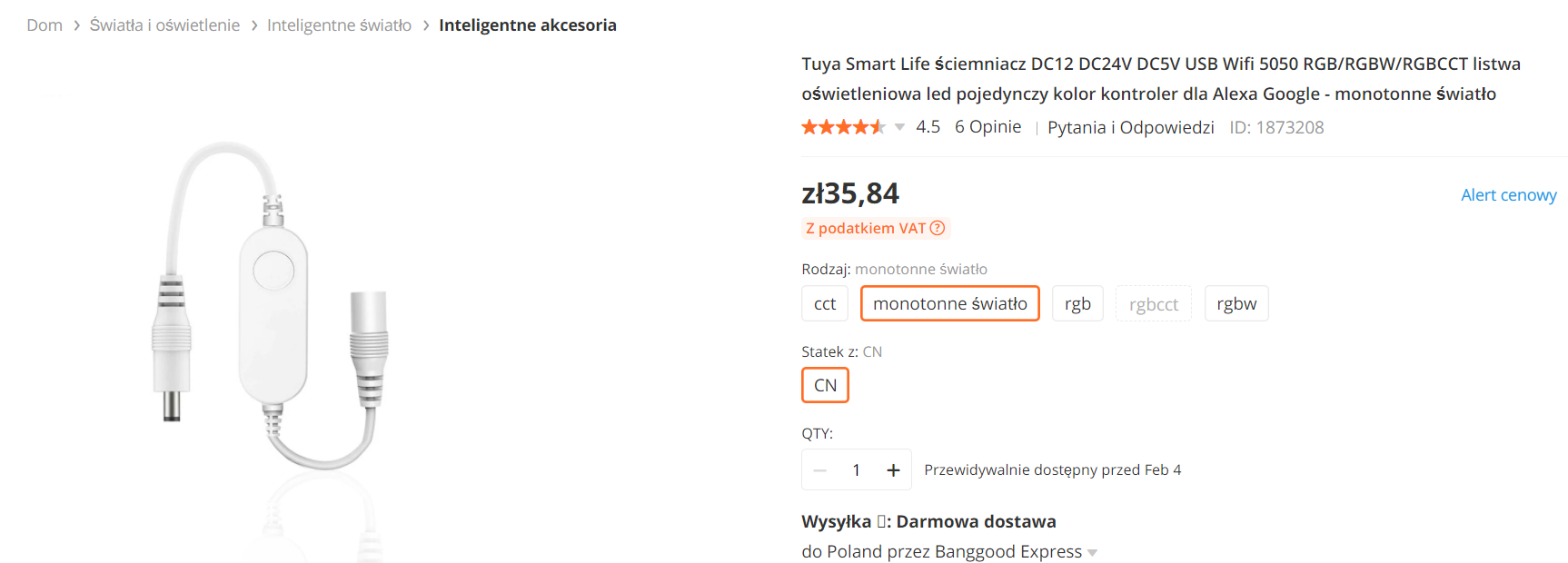
Purchase and first impression I found the dimmer on the network under the password
Tuya Smart Life Dimmer DC12 DC24V DC5V USB Wifi 5050 RGB / RGBW / RGBCCT Led Light Strip Single Color Controller for Alexa Google - Monotone Light for about $ 10 (including shipping), or PLN 40. Below is a screenshot of the offer (as I was buying, the price was probably slightly different):
Working parameters according to the seller:
Quote:
Item Type: RGB Controler
Material: Plastic
Power Source: DC
Voltage: DC 5-24V
Max. Load Power: 96W
Wattage: 96W
Remote Distance: about 20m
Applicable Lights: DC5-28V
Oscillation frequency: 2.4G
Model Number: WIFI 371
Controled Method: Smart phone APP control
Connection Mode: Commond connect
Certification: CCC CE ROHS
Features: Single Color WIFI controller
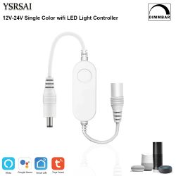
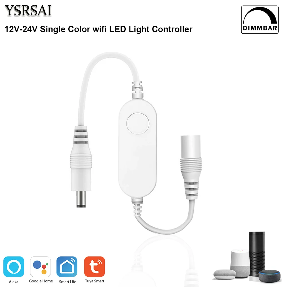
Artwork from the seller:
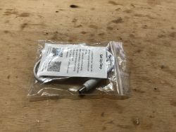
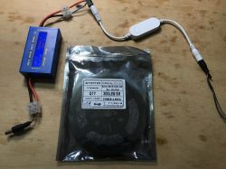
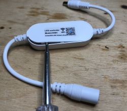
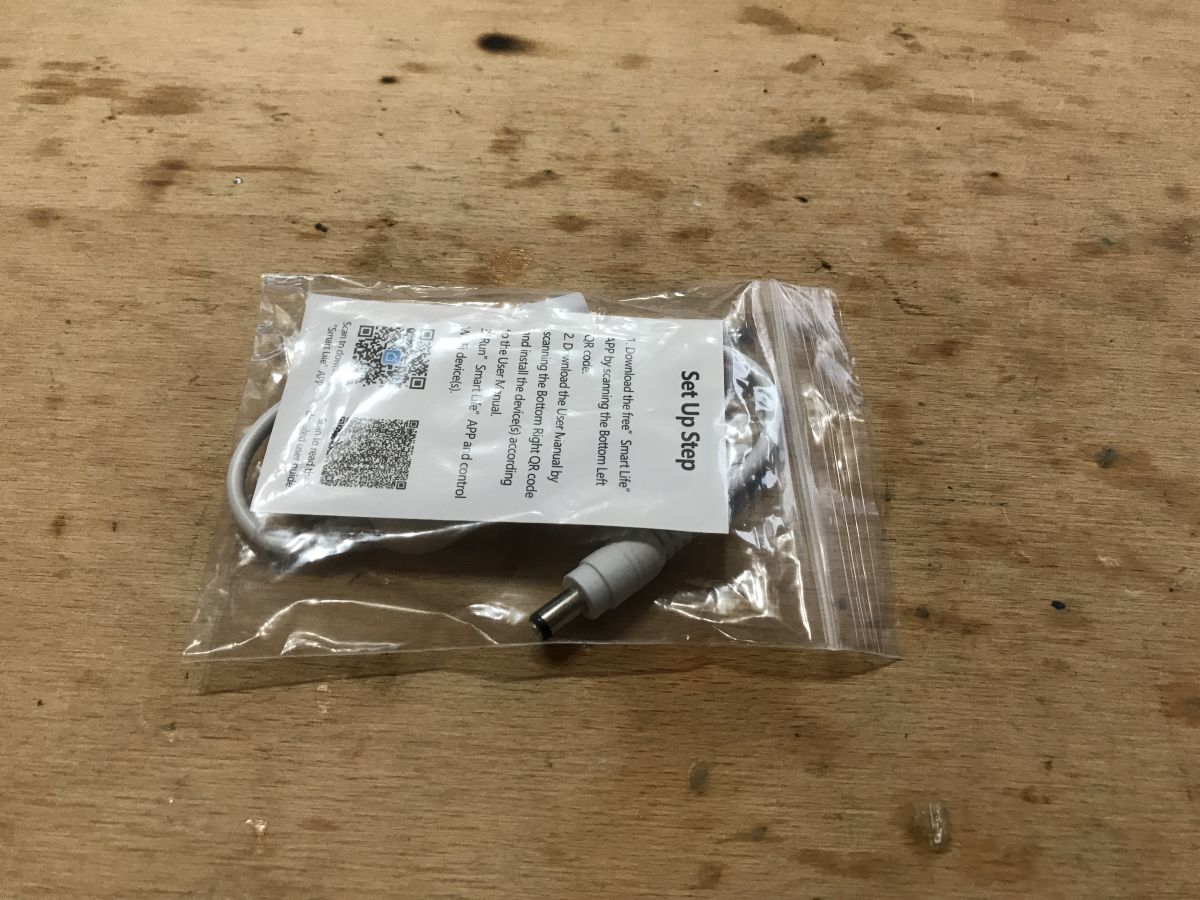
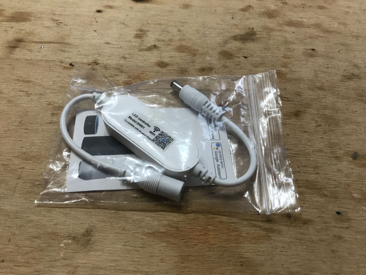
The product itself came to me in such a bag, without instructions but with QR codes:

However, QR codes lead to:
https://www.evernote.com/shard/s223/client/sn...cd37a43aef1599b0e3&sn=https%2F2.%3%ardote.com 2Fsh% 2Feb53e52d-3397-489b-979a-3b7ca059a3ce% 2F70498f1cd35bf8cd37a43aef1599b0e3 & title = USER% 2BMANUAL
Below I am attaching the instructions from this link:
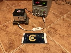
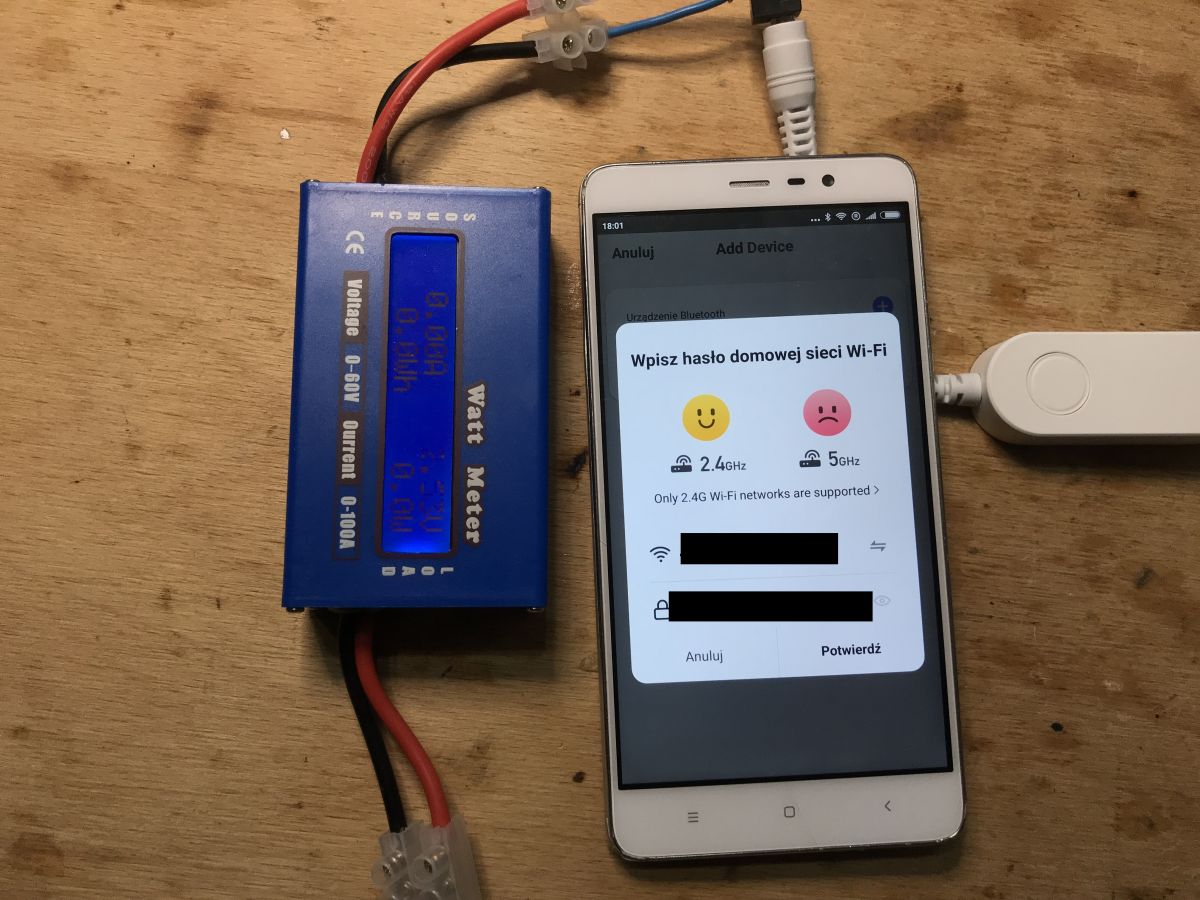
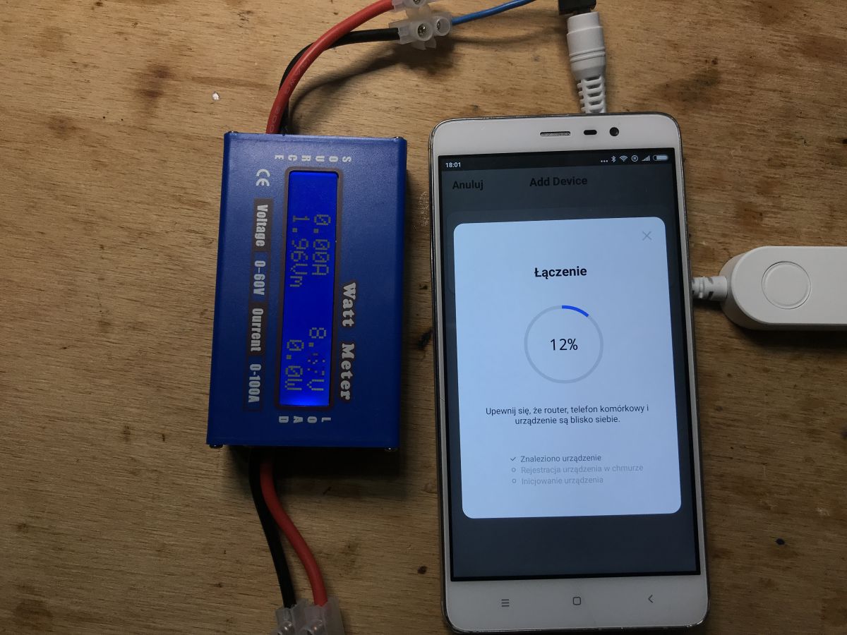
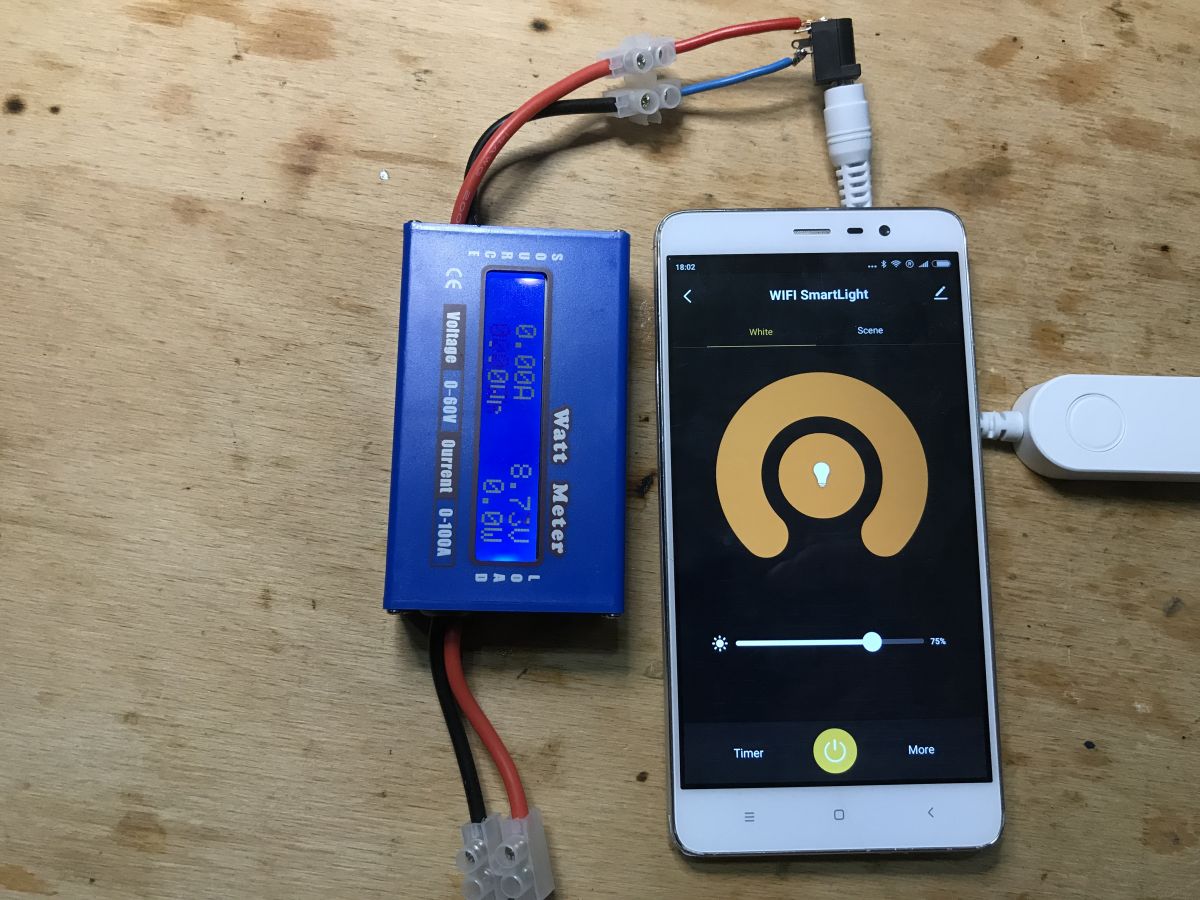
Wi-Fi Ligh...Manual.pdf (995.51 kB)You must be logged in to download this attachment. Wi-Fi LED ...Manual.pdf (2.02 MB)You must be logged in to download this attachment. Pairing with the application Pairing is really very simple. The dimmer was detected automatically, I barely launched the SmartLife application on my Android phone (without that, you probably would have to put it into the Reset state by pressing the button for a long time):
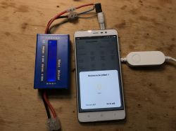
The device is displayed under "bluetooth devices":
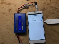
You need to enter the password of our WiFi network, it must be a 2.4GHz network (5GHz is not supported):

Evaporation:
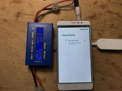

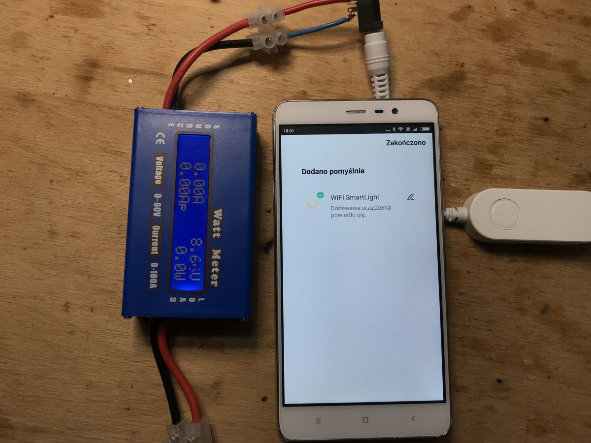
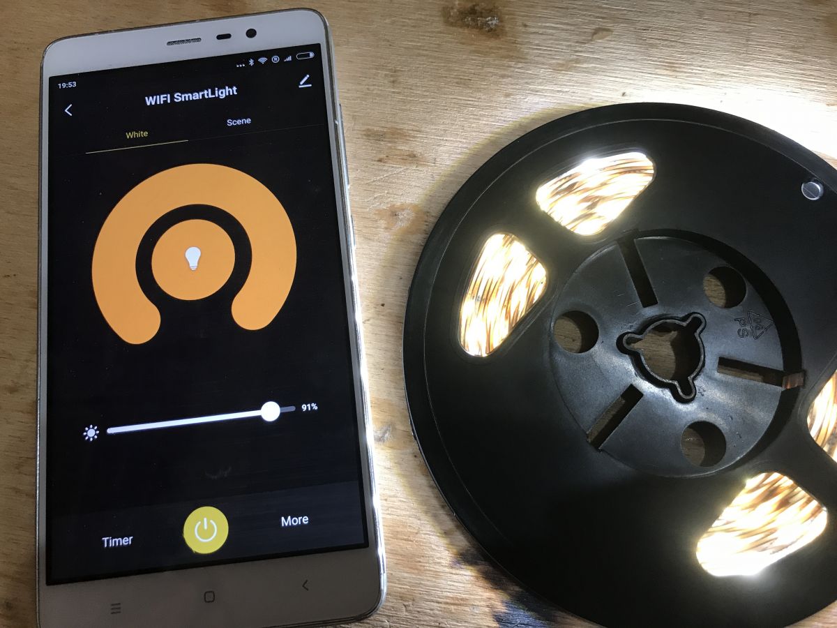
After pairing, we get smooth brightness control and the ability to turn on / off via WiFi:
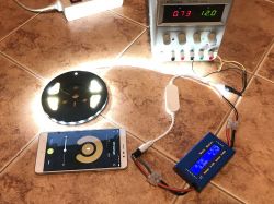
 LED strip test
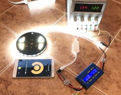
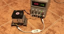
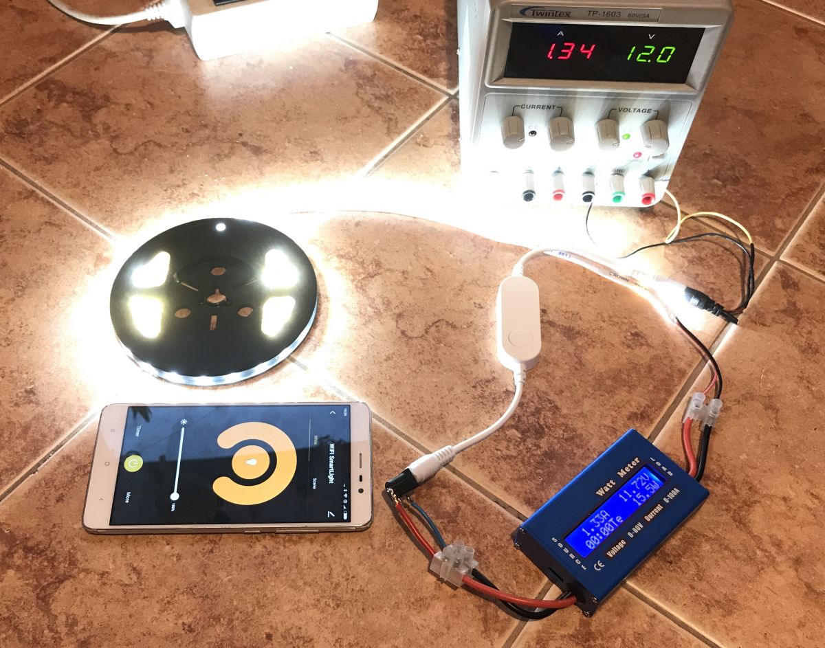
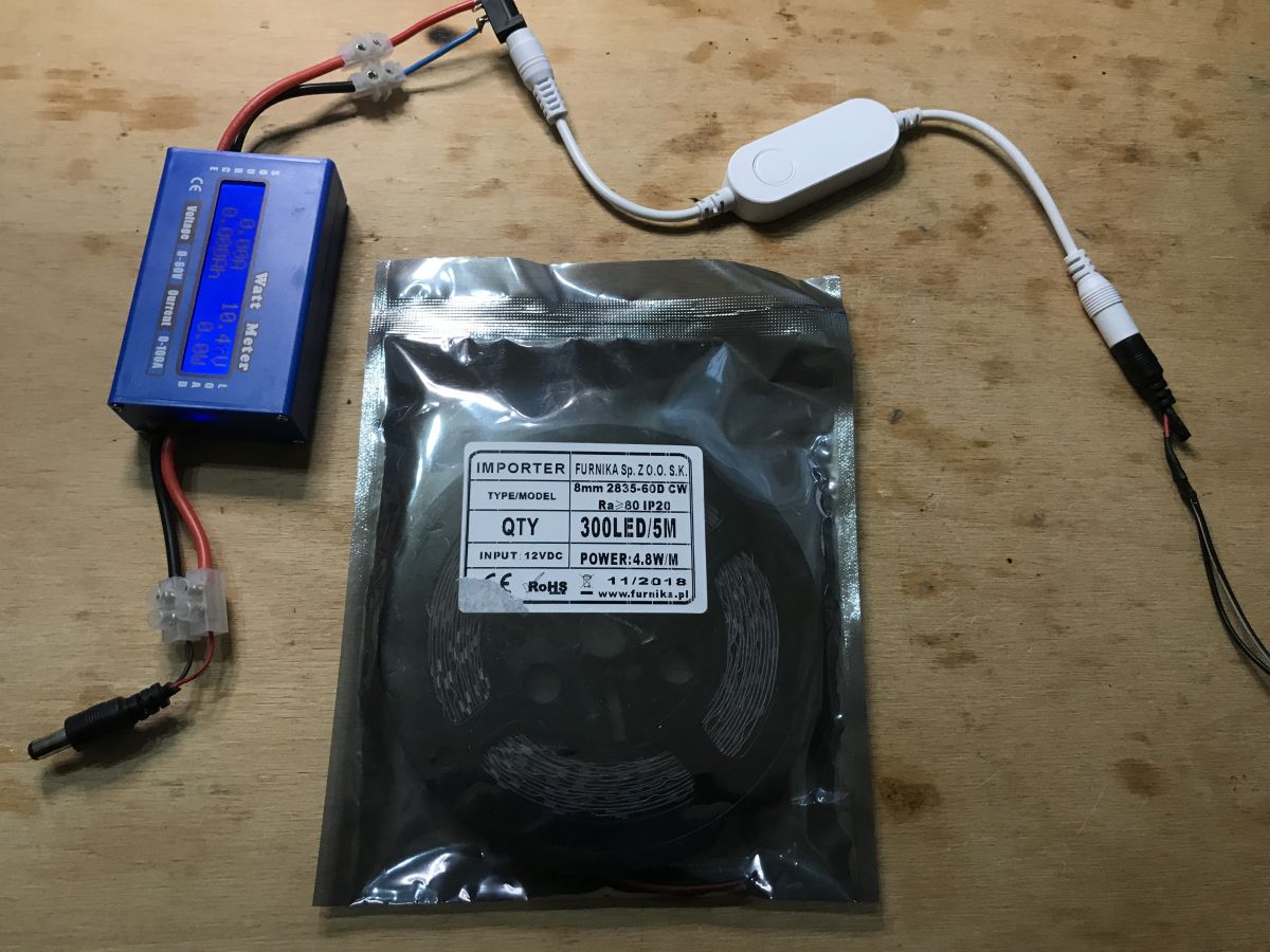
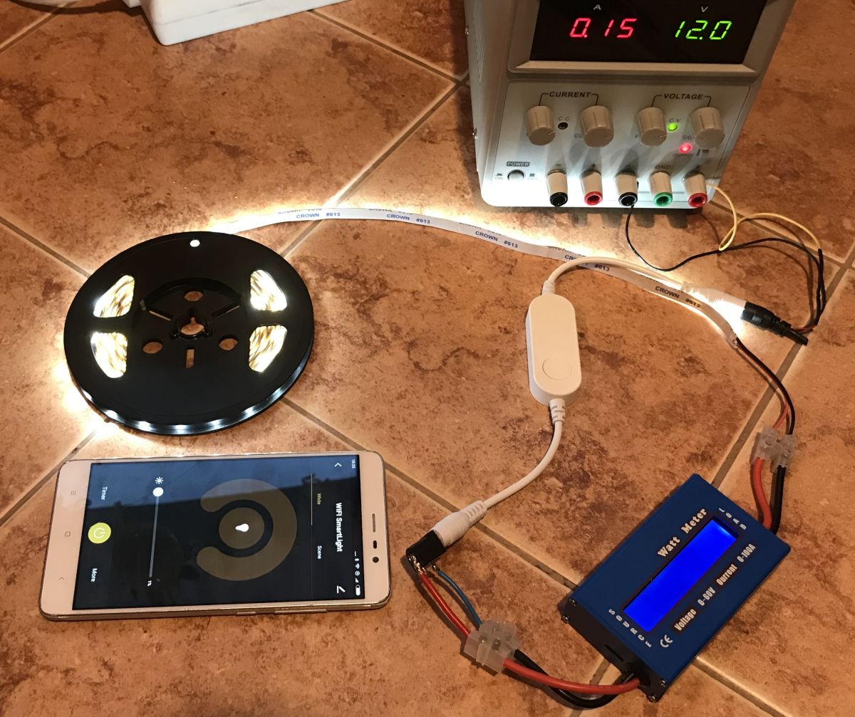
 It's time to test with the LED strip, here the white strip at 12VDC, 5 meters, 4.8W * 5 = 24W (in practice it turned out to be smaller, but this is not the case).
For the test, I used the Twintex TP-1603 laboratory power supply. The output voltage is 12V, you can read the current from the photos. Additionally, a second "Watt Meter" is plugged in behind the tested device.
Full brightness:
50%:
1%:
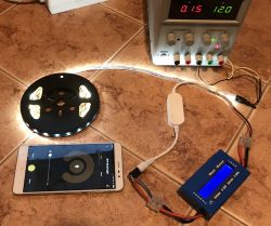
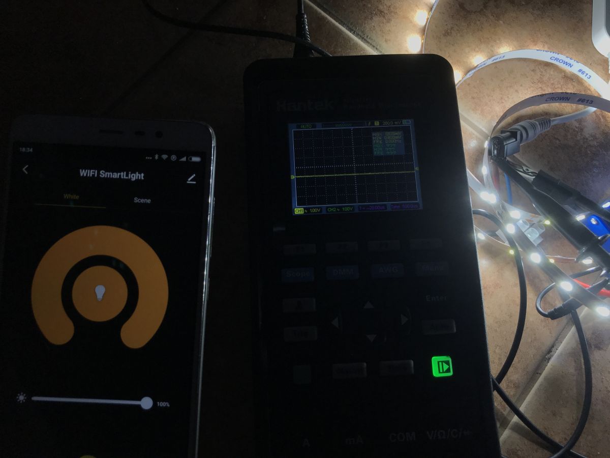
Let's see how the lighting power is regulated. Obviously, this is a 1kHz PWM. The LEDs are simply turned on for a given time and then turned off, but it is done so quickly that the human eye does not feel the flashing.


NOTE: Do not turn on such LED strip for more than a few moments without unfolding. It can get really hot.
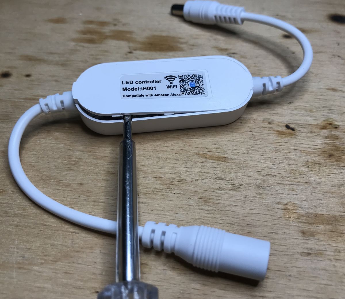
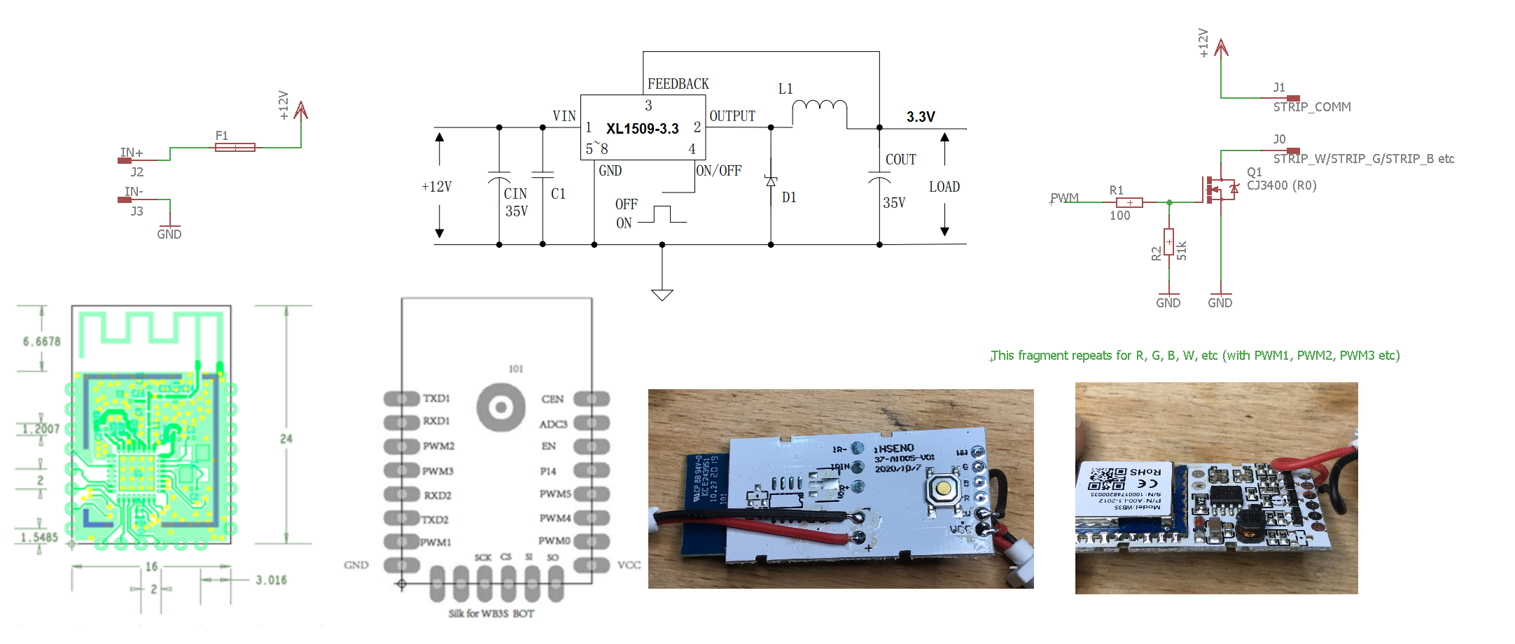
Interior There are no screws, we just pry up the base:
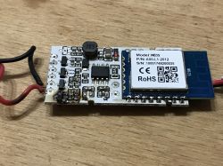
And we immediately see the interior:
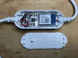
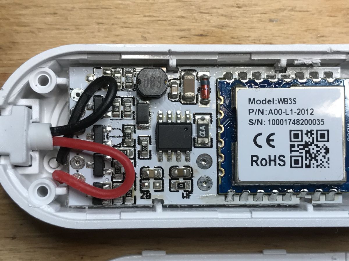
Unfortunately, this is not for any ESP8266 or ESP8285 (TYWE3S, TYWE2S). This is WB3S:
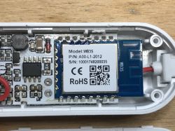
WB3S, an energy-saving WiFi + Bluetooth module from Tuya, based on the BK7231T chip.
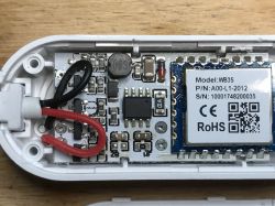
Additionally, we have what looks like a converter and transistors:
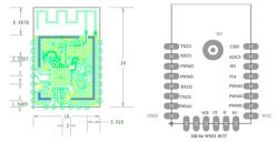
From the bottom, we have space for additional layouts. There are no programming pins. There are pins with roles:
- IR-, IRIN - probably this board also supports remote control in another version ...
- W, R, G, B - this PCB probably also supports separate control of 4 channels in a different version (separate PWM for R - red, separate for G - green, etc., red green blue white).
Let's take a better look at the inverter:
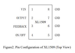
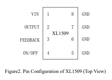
The converter is a xl1509-3.3e1 by XLSemi.
It is more precisely a step down converter (buck) which works on input voltage from 4.5V to 40V, and gives 3.3V at the output (there are also versions giving 5V and 12V). So this circuit provides power to the WB3S.

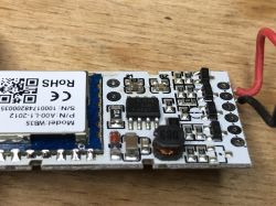
There are still transistors. The designation for R0 might point to a few different ones, but my searches show that these are probably CJ3400 or similar:

So MOSFET transistors with an N channel in the SOT-23 housing, with a very low RdsON, just right for switching high currents.
There is also a fuse on the board, which is always a plus in this type of product.
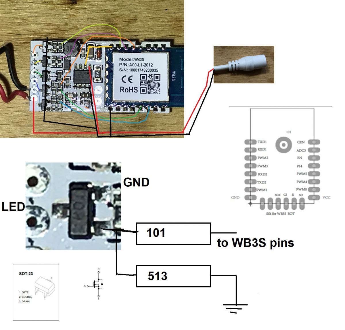
Diagram Finally, I decided to sketch a schematic of the entire circuit. It is based on the Eagle and diagram in Application Note XL1509.
First, the 'rough draft':

And the diagram:

A few notes about the scheme:
- on the board we have 5 places for transistors (4 of them are occupied), but only one transistor is used (I do not know why the others are soldered, maybe the manufacturer initially made the RGBW version and then changed his mind)
- transistors are controlled by the PWM outputs of WB3S (PWM frequency is 1kHz)
- I have the impression that there is one additional diode on the board that is not in the diagram, it is related to the step down converter circuit, probably there is some additional protection
Catalog notes of the elements from the inside:
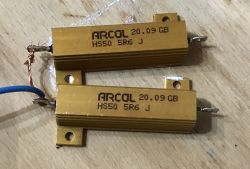
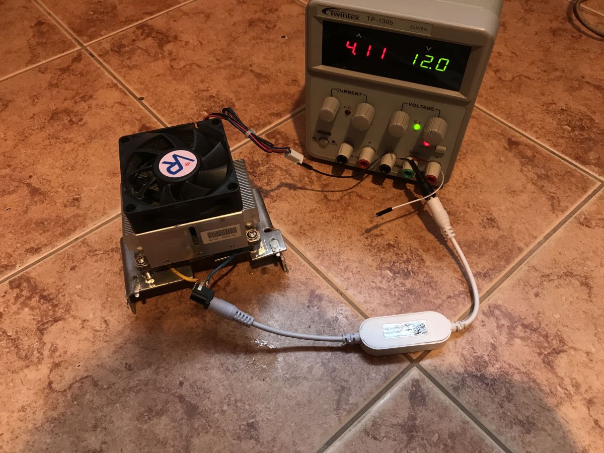
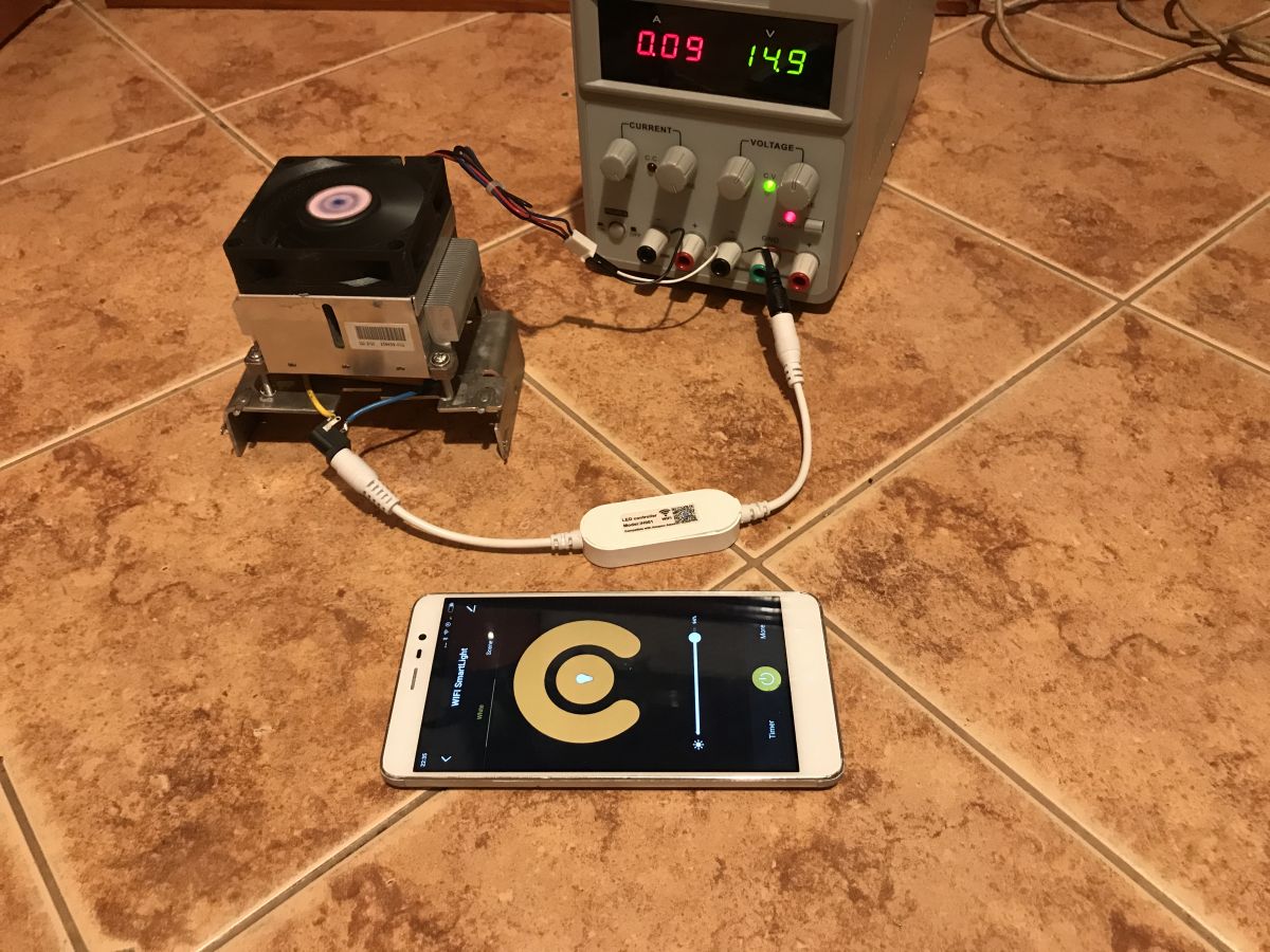
CJ3400_C19...ech-CJ.pdf (169.13 kB)You must be logged in to download this attachment. XL1509 dat..eet.pdf (383.28 kB)You must be logged in to download this attachment. BK7231T CO...tation.pdf (6.07 MB)You must be logged in to download this attachment. WB3S Modul...cs (3).pdf (636.03 kB)You must be logged in to download this attachment. Test under load - 48W I was about to finish, but I was tempted to check how much this device heats up, at the beginning with a load of 48W. For this I used 50W 5.6 ? wire resistors, two connected in parallel give 2.8 ?. When powered by 12V, a current of about 4.28A should flow, but this is without taking into account the voltage drop across the MOSFET in the center of the circuit.
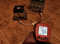
Test circuit - Twintex TP-1305 power supply. At 12V, it flows at 4.11A:

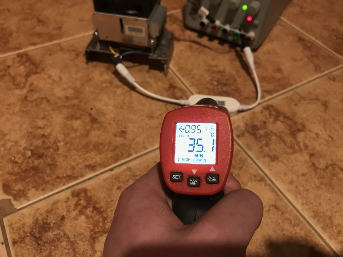
After a few hours:

Only 35 ° C, so approx.
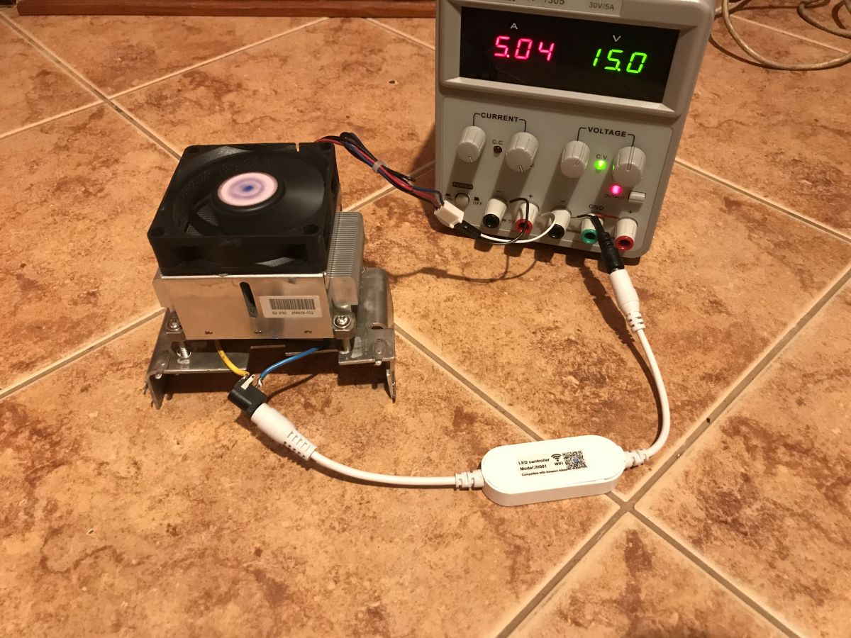
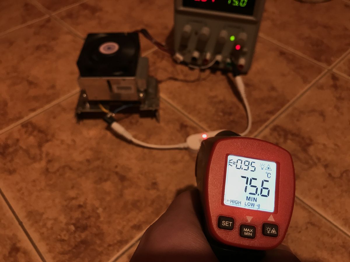
Test under load - 75W At around 48W it was okay, what will be at 75W? According to the manufacturer, up to 96W is ok ... we will check. I increased the voltage to 15V:

After about an hour:
A little later - a sad surprise. There must have been damage, burnout of the transistor and an interruption of the circuit:
75W was too much for this device.
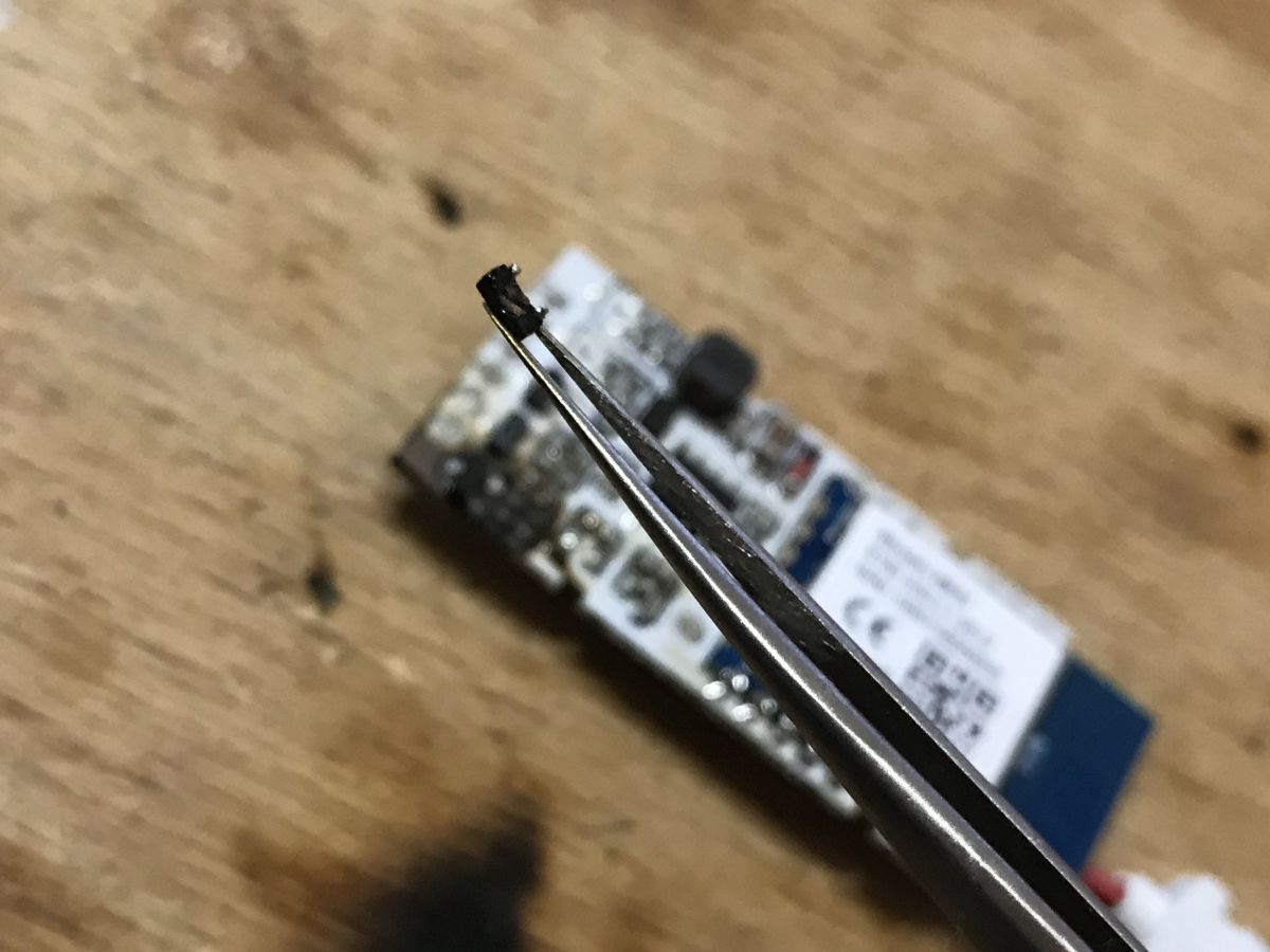
Repair after damage Well, now let's look inside what broke. Initial test shows that the WiFi module is still working and the phone sees the device:
The defect is obvious - the transistor has burned out. The resistors are ok. The transistor is now a break in the circuit:
Fortunately, we have three spare pieces, right next to the PCB. As I wrote earlier, they are not used by the system, I do not know why the manufacturer soldered them there.
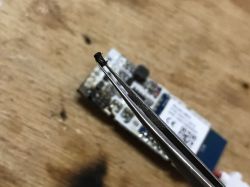
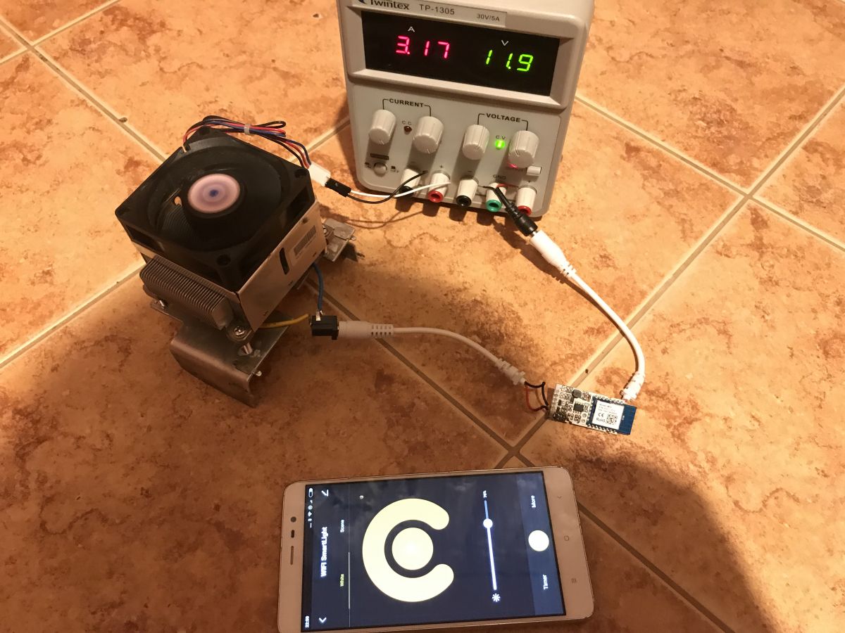
After replacing the transistor, everything works again:
 Can the device be controlled when we disconnect the router from the Internet (but the phone and the device are in one LAN)?
 I checked it by simply disconnecting quite the main cable from the router. I don't have any mobile internet on my phone, so my LAN has been separated from the world:

Even so, you can still control the brightness from the app. Another plus for this product.
Summary The product works well with the SmartLife application, but unfortunately we cannot upload open software such as Tasmota / Domoticz because it is not implemented on ESP, but on WB3S. This greatly limits the potential use of it in DIY.
The only hope is that the outputs are compatible with TYWE3S / ESP12 so that it can be easily soldered there, but then I do not know about PWM - maybe they would have to be implemented by software.
As for the rest of the circuit, the 3.3V power supply is done on the XL1509 step down converter and the switching (and PWM dimming) on the CJ3400. In addition, you can see that the product was initially prepared to separately control the RG and B channels of the strips, there are even additional transistors soldered to it. Maybe it could be modified to support it, if the WB3S SDK was run (in fact, you could probably even modify it to control ws2812b, only then you need a separate power supply and a separate pin with the control signal).
In terms of power, the product can handle around 48W of the load without any problems, while 75W is too much for it and ends up with a burnout of the transistor. So the seller is exaggerating a bit by advertising it as "up to 96W". But I didn't expect that much power anyway, so the 48W LED strip on one transistor is also good.
Anyway, it's not bad, but I'll be looking for a similar product anyway, only for ESP.


Comments
Cool. I can't see Alexa cooperation tests. No external control tests. For example, a device connected to the home WiFi network and control from a phone from the mobile Internet, we do not know if it... [Read more]
It was tested at the beginning of the series (probably one of the linked topics) and I do not repeat these tests anymore as there is another device from the SmartLife / eWeLink / Tuya / Blitzwolf series.... [Read more]
Yes, I know. I have several devices that work with this application. However, I chose Mi-Light to control the lighting. In addition to the app and Alexy, they offer remote control and wall panels. My bulbs... [Read more]
To me, it looks like a PCB "universal" for various programs - from one channel / color to 5. Contrary to appearances, making a PCB for full filling in SMD and only partially does not differ significantly... [Read more]
Is the layout of the photo known? I'd like to modify it. Add a relay control output (if RGB works, it should disconnect the main lamp and enable full 100% PWM on all channels because G / B are about... [Read more]
I think I have it: https://obrazki.elektroda.pl/5496610300_1670846238_thumb.jpg https://obrazki.elektroda.pl/4550409000_1670846238_thumb.jpg The programming and configuration procedure is as... [Read more]