Reflashing a MOES/Andeli TuyaMCU glass-panel Wi‑Fi wall switch with OpenBeken and linking it to Home Assistant.
The switch uses a WB2S main board and a relay/power daughter board; OpenBeken maps TuyaMCU channels through autoexec.bat with startDriver TuyaMCU and linkTuyaMCUOutputToChannel.
The device is rated for 100-250V 50/60Hz, 10A, and 2.4GHz Wi‑Fi.
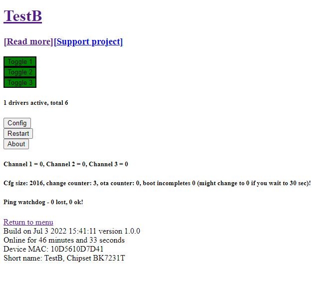
After reboot, the relay buttons appear in OpenBeken and Home Assistant can control each gang through MQTT like an ordinary switch.
dpID1-dpID4 control the relay states, while dpID7-dpID10 are optional delayed-toggle values; the mapping can differ across switch versions.
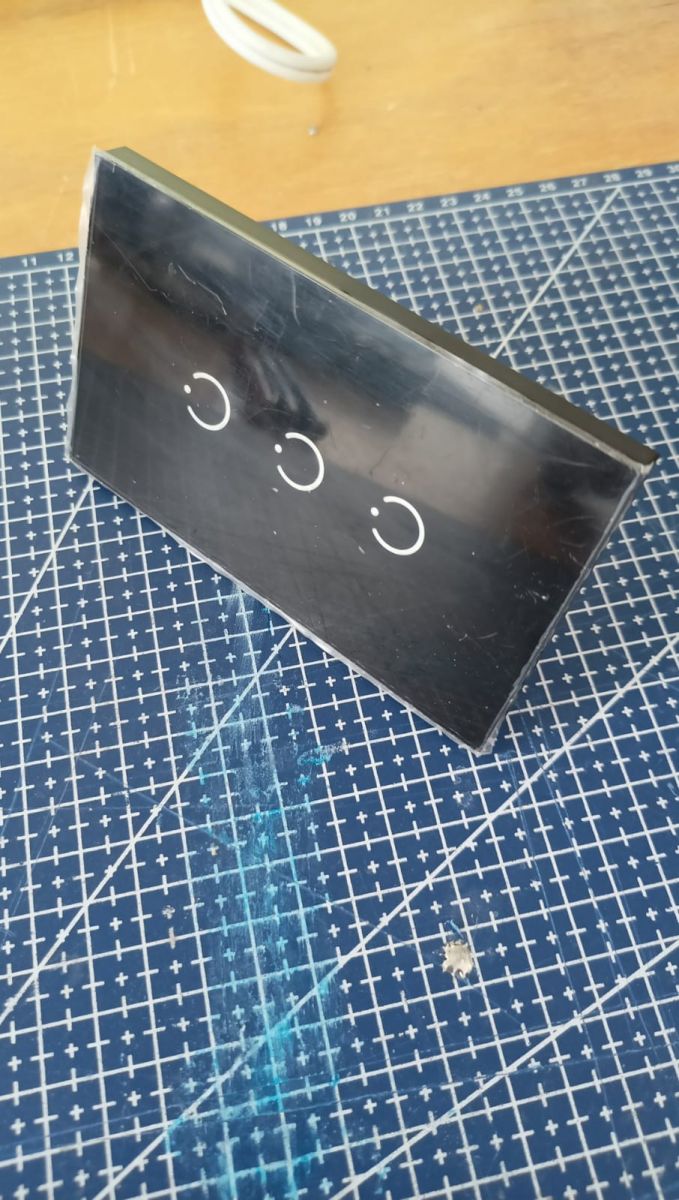
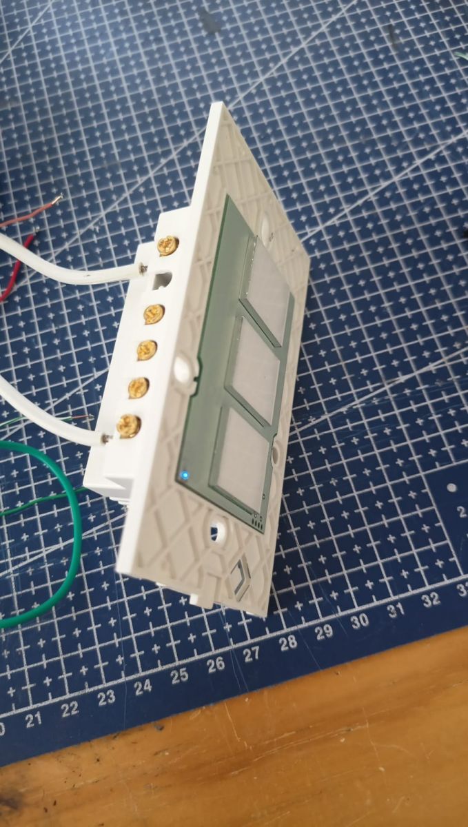
Where to purchase the switch The switch was bought from AliExpress by searching: ANDELI Tuya Smart Life Wifi Light Switch with Glass Panel US Standard Touch Sensor Wall Switches Voice Control Alexa Google Home However, other people refer to this switch as a MOES Switch so it's very likely that this is a dropship product and multiple brands will have the same internal components.
The voltage range of the device is 100-250V 50/60Hz and a max current of 10A. It connects to WiFi using a 2.4GHz signal.
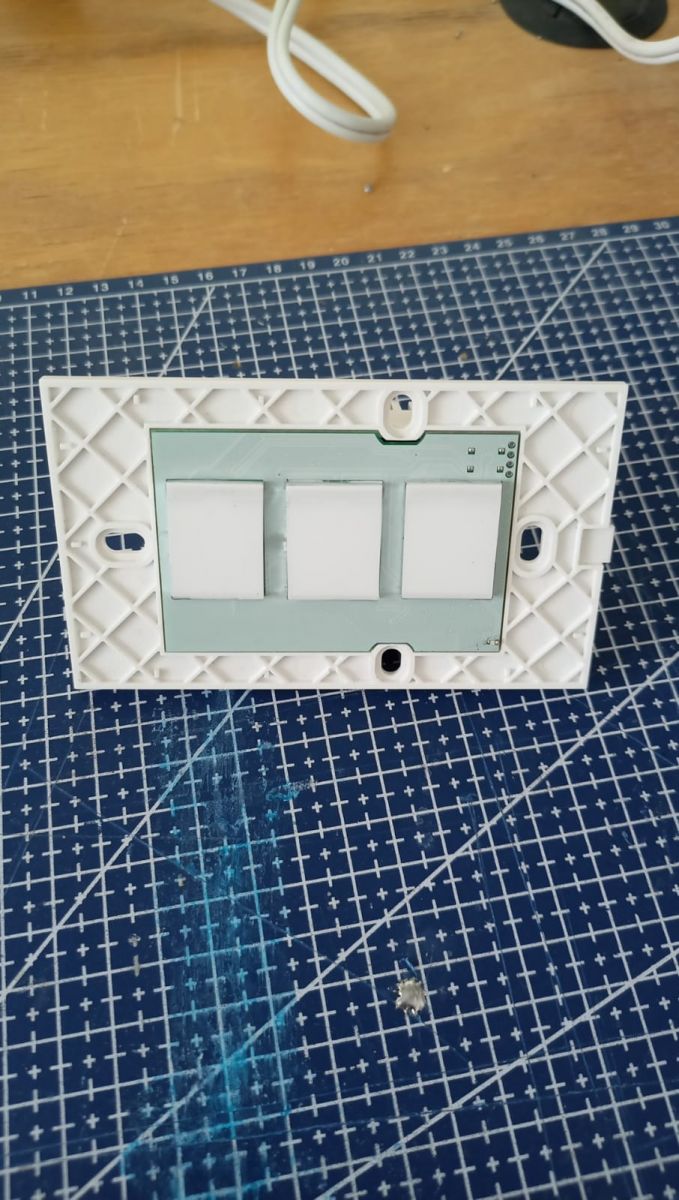
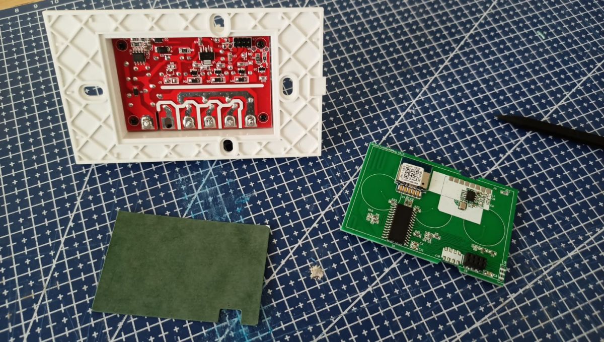
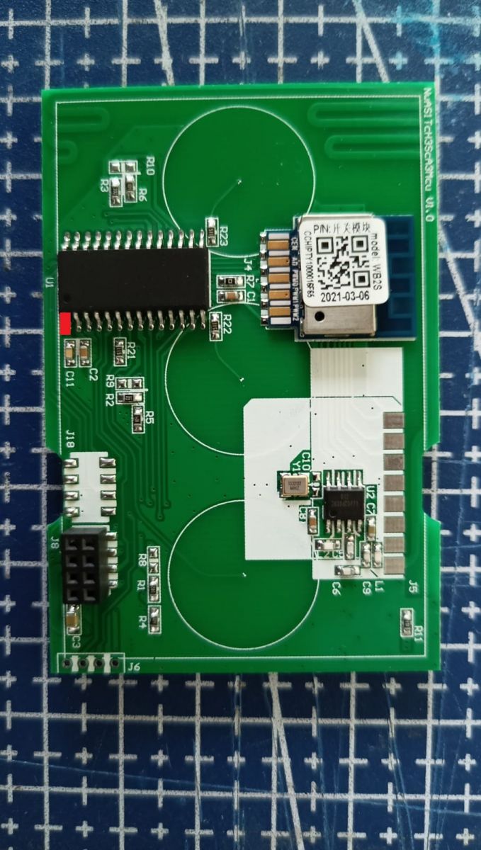
The interior of the switch Since it is designed to be mounted on a wall, the glass plate can be easily removed, allowing us to dissasemble it without any tools. The switch is composed of two boards, the main board: Where the TuyaMCU and the WB2S chips are located, and a daughter board, where the relays and power are located.
We are only interested on the main board.
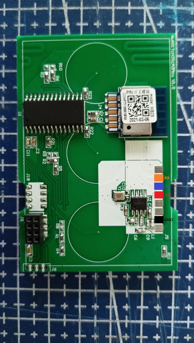
Flashing the WB2S The main board comes with some pads that link directly to VCC, GND, TX and RX. Here is an example of which ones where on my board. Verify that they are correct in your board, as I've seen other revisions on the internet.
I did some tests and it seems that it is not necessary to remove the TuyaMCU chip from the board for the WB2S however, in case that you're having troubles, desolder pin 1 to disconnect it
Flash the chip following the instructions from OpenBeken in my case, I was only able to do it using python. The flash tool needs to be at 3.3V
Once the chip is flash it, remove the soldered cables, reconnect the TuyaMCU if you had desoldered it and reassemble the box, as it seems that the TuyaMCU does not fully boot unless it is plugged to the daugtherboard (probably the reason we can flash it without desoldering).
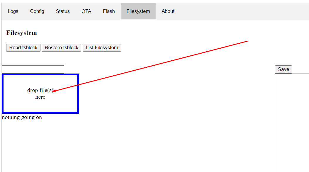
OpenBeken configuration After basic configuration is done (see OpenBeken), a startup file named autoexec.bat with the following contents.
In the App panel, drag the file to the OBK file system:
This file will be automatically executed after every reboot. It needs to be restarted manually the first time
Meaning of individual commands:
- startDriver TuyaMCU - runs the TuyaMCU driver
- setChannelType n toggle - set the type of channel number n to On / Off
- linkTuyaMCUOutputToChannel n bool 1 - connects TuyaMCU dpID number 1 with bool type channel number 1
The dpID values can be different for different kinds of devices. If we want to add support for something new, we need to get to know it, e.g. by listening for packages. The dpID values can also be taken from the descriptions of devices intended for Tasmota, because Tuya often only changes the WiFi module and the rest remains the same.
In the case of this switch there are 4 dpID values (dpID1 trough dpID4) that set the state of each relay, there are four as this chip is used for al versions of switch (from 1 to 4 gang), so only the dpID's for the switches that are physically present are needed.
There is another set of 4 dpID (dpID7 to dpID10) which are of type val which toggle the relay after a number of seconds have passed (the user input's the number) I didn't link them as I don't have any use for them, however I'll document it in case they are needed for your application.
After restarting, the buttons are now visible:
Home Assistant Support Pairing with Home Assistant is very simple, all thanks to the automatic mapping of OpenBeken channels to TuyaMCU variables. The TuyaMCU switch is operated from the HA level in the same way as an ordinary switch. Here is a sample Yaml code:
In this video ("Final test") you can not see what is happening when controlling from a smartphone. Unless my browser is hiding it. [Read more]
p.kaczmarek2
08 Jul 2022 14:09
Thank you for inserting the test and I'm glad that TuyaMCU works for you. Basically, I tested TuyaMCU only on the basis of the Moes dimmer, but I can see that the well-implemented protocol also works... [Read more]
krisRaba
08 Jul 2022 14:29
There is probably a white backlight of the circle and at least on the second and third individually switched on, you can see that the backlight turns on gently ... But you actually have to strain your... [Read more]
Anonymous
08 Jul 2022 14:35
The author should frame the video to the smartphone itself and this gadget from Tuya. It does not matter that it has four T12 bits :) [Read more]
FAQ
TL;DR: 100-250 V input range and 10 A load make the TuyaMCU wall switch globally usable; "well-implemented protocol" enables painless OpenBeken flashing [Elektroda, Tow96, #20092751; Elektroda, p.kaczmarek2, #20093348]. Reflash WB2S at 3.3 V, drop an autoexec.bat, and link up to three gangs to Home Assistant in ≈15 min.
Why it matters: One inexpensive cloud-free flash puts your smart wall switch fully under local MQTT control.
What hardware sits inside the MOES/Andeli Tuya wall switch?
The main board holds a WB2S Wi-Fi module and a TuyaMCU coprocessor; a separate daughterboard carries the 10 A relays and power supply [Elektroda, Tow96, post #20092751]
Which pads do I connect to flash the WB2S?
Locate the VCC, GND, TX, and RX pads shown in the teardown photo, then verify the silkscreen because board revisions differ [Elektroda, Tow96, post #20092751]
Must I desolder the TuyaMCU before flashing?
Usually no. Tests show WB2S enters bootloader without removing TuyaMCU; if flashing fails, lift TuyaMCU pin 1 to isolate RX [Elektroda, Tow96, post #20092751]
What voltage and tool should I use to flash OpenBeken?
Unsolder wires, re-attach daughterboard, power up. The TuyaMCU only boots when both boards are connected [Elektroda, Tow96, post #20092751]
How do I configure a 3-gang model in OpenBeken?
Drop an autoexec.bat containing three pairs of setChannelType and linkTuyaMCUOutputToChannel commands (dpID 1-3). Reboot once to load them [Elektroda, Tow96, post #20092751]
Create MQTT switch entities pointing to topic //set and /get; OpenBeken auto-maps channel states, so no extra templates are needed [Elektroda, Tow96, post #20092751]
Why is the backlight barely visible in the demo video?
LED rings glow softly; viewers needed to "strain your eyesight" to notice changes, as noted by forum users discussing the clip [Elektroda, krisRaba, post #20093383]
What should the video have shown on a smartphone?
It should display on-screen toggles switching while the physical LEDs react; the posted video did not frame the phone, causing confusion [Elektroda, khoam, post #20093237]
Flashing the 600 kB OpenBeken binary at 115200 bps finishes in about 45 s, excluding solder time [OpenBeken Docs].
What language improvements are planned?
Polish strings will be cleaned up; current interface uses machine translation, "there are incomprehensible fragments" per maintainer [Elektroda, p.kaczmarek2, post #20093348]

Comments
In this video ("Final test") you can not see what is happening when controlling from a smartphone. Unless my browser is hiding it. [Read more]
Thank you for inserting the test and I'm glad that TuyaMCU works for you. Basically, I tested TuyaMCU only on the basis of the Moes dimmer, but I can see that the well-implemented protocol also works... [Read more]
There is probably a white backlight of the circle and at least on the second and third individually switched on, you can see that the backlight turns on gently ... But you actually have to strain your... [Read more]
The author should frame the video to the smartphone itself and this gadget from Tuya. It does not matter that it has four T12 bits :) [Read more]