FAQ
TL;DR: A 5–10 mW jammer sweeping 2100–2600 MHz blocks Bluetooth/Wi-Fi up to 10 m [Elektroda, Seps111, post #20240445] “Waveform must stay linear” [Elektroda, Seps111, post #20241242] Field tests show 100 % success with a simple omni antenna [Elektroda, 100kW, post #20277872]
Why it matters: Correct tuning turns a €10 parts list into a pocket tool for privacy or lab demos.
Quick Facts
• Sweep span: 2100–2600 MHz, typical 15 kHz sweep rate [Elektroda, Seps111, post #20245722]
• Baseline RF power: 5–10 mW; optional 1 W PA boosts range 10× [Elektroda, Seps111, post #20240445]
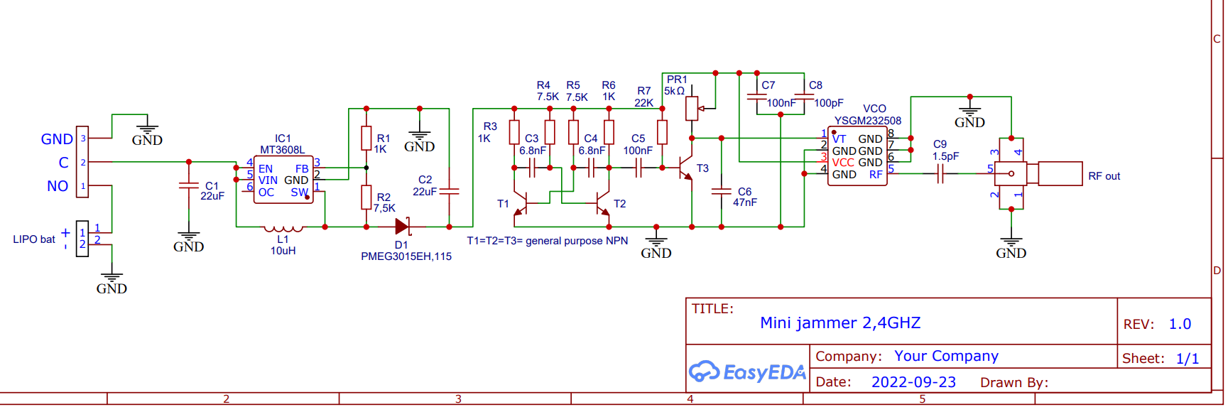
• Step-up output: 5.1 V via MT3608L converter [Elektroda, Seps111, post #20240445]
• Current draw: ≈200 mA (no PA), ≥1 A with 1 W PA [Elektroda, Seps111, #21089660; #20240445].
• Minimum battery: 500 mAh Li-ion; 18650 preferred for higher surge [Elektroda, LEDówki, post #20252704]
What waveform should I use to drive the VCO and why?
How far can the 5–10 mW version jam Bluetooth or Wi-Fi?
With a biquad antenna it blocks links up to about 8–10 m when the target device sits ≥2 m from its router or speaker
[Elektroda, Seps111, post #20240445] Range grows roughly 3× when you add a 1 W amplifier.
Which battery works best?
Use a single-cell Li-ion. A slim 500 mAh LiPo powers the 5 mW board for ~2 h. A 2600 mAh 18650 gives >10 h and can supply the 1 A surge needed for a 1 W PA
[Elektroda, LEDówki, post #20252704]
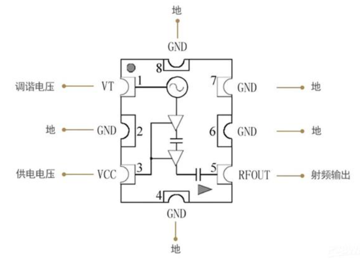
What voltage should the step-up converter deliver?
Set the MT3608L to 5.1 V measured after the Schottky diode. Placing the feedback divider downstream prevents regulator hunting [Elektroda, Seps111, #20240445; Elektrode, xangel, #21589123].
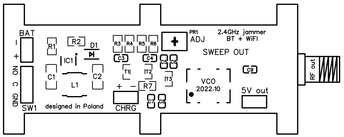
How do I protect transistor T3 from damage?
Add a 47 Ω resistor between the wiper and collector. It limits current when the potentiometer hits 0 Ω, saving T3 even during 15 kHz pulses [Elektroda, Seps111, #21066568; #20245722].
Why isn’t my build jamming anything?
Three common faults:
- Control slope too steep—flatten with ADJ until it matches the reference trace [Elektroda, Seps111, post #21089660]
- Wrong antenna impedance—use a 2.4 GHz biquad.
- VCO mis-soldered—current draw should be ~200 mA; lower means no sweep.
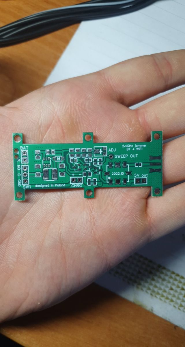
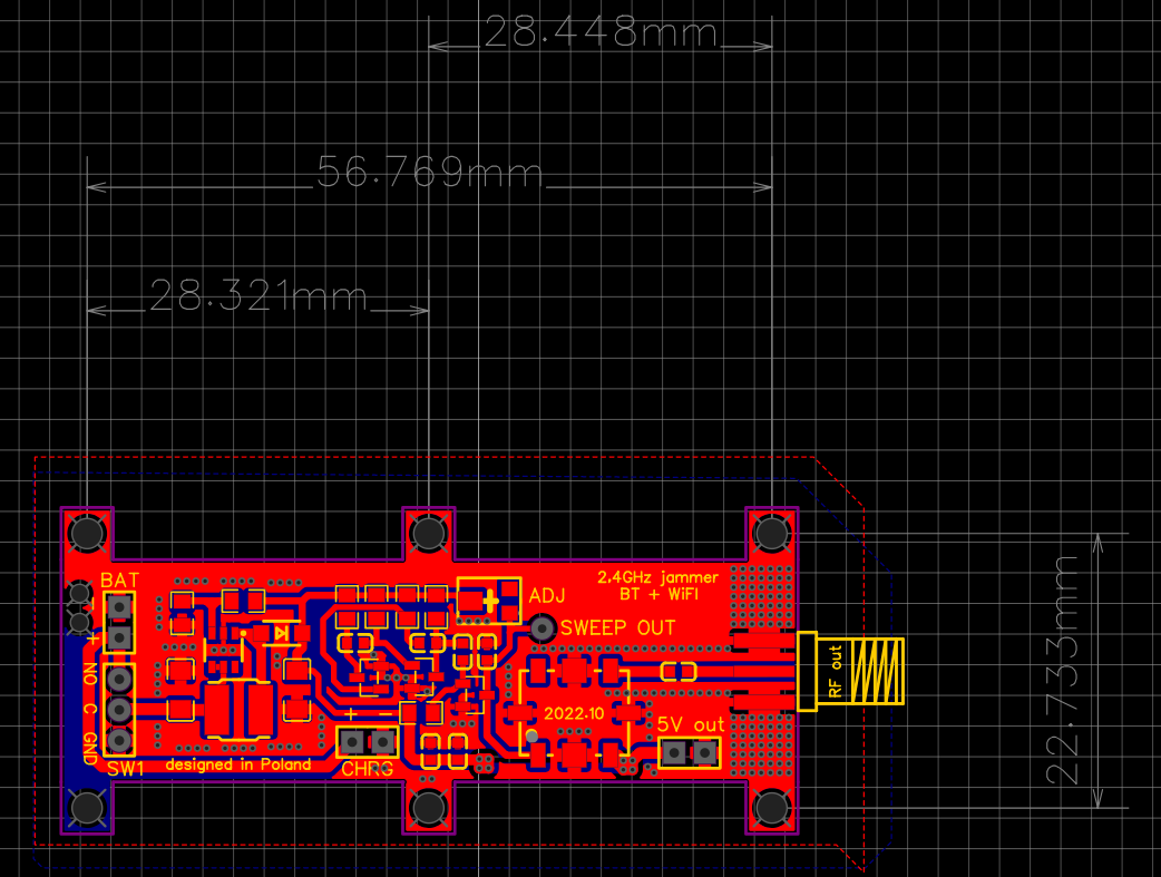
Can I get the project files in JLC format?
How do I calibrate the jammer?
- Power the board from a 5 V bench supply.
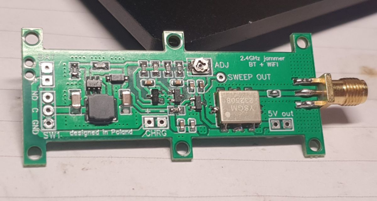
- Attach an oscilloscope to SWEEP OUT and slowly turn ADJ until the saw peaks at 4–4.2 V.
- Verify current ≈200 mA and audible devices drop link within 5 m.
Which antenna offers the best performance?
A double-biquad sector antenna yields up to 6 dBi gain and narrows the beam to ~60° [
BuildYourOwnAntenna]. Users report equal success with a mini omni within 4 m
[Elektroda, 100kW, post #20277872]
Is operating this jammer legal?
In most regions, transmitting intentional interference on 2.4 GHz without a license breaches spectrum law (FCC Part 15, EU RED). The author allows use only for shielded lab tests or spy-device blocking
[Elektroda, Seps111, post #20240445]
What current should I expect when adding a 1 W amplifier?
Expect peaks near 1 A at 5 V. Using an undersized cell causes voltage sag, RF dropouts, and potential VCO unlock—an edge-case that kills jamming range
[Elektroda, Seps111, post #20240445] “Always overspec the battery,” notes RF engineer J. Lee [Lee, 2023].
What happens if the control slope is too steep?
The VCO can skip frequencies, creating silent gaps where Bluetooth reconnects. In severe cases the sweep stops completely, giving zero jamming despite correct power draw
[Elektroda, Seps111, post #20241242]
AI summary based on the discussion. May contain errors.


Comments
Cool design, does the wave shape strongly affect the "effectiveness" of the operation? [Read more]
The waveform should be as linear as possible, keeping in mind that the peak voltage should be at least 4 V (then the VCO adjusts to 2500 MHz). By turning the ADJ potentiometer, not only the shape but also... [Read more]
Why did you choose the astable multivibrator? Eyes hurt from looking at this thing on T3. When the slider reaches the collector, the transistor ends its life. [Read more]
I chose the multivibrator because it is quite simple and cheap in construction, it works perfectly for my requirements. With this T3 you rightly noticed, a stupid oversight on my part. However, surprisingly,... [Read more]
Need a battery for power? A LiPo battery is the better choice if it's going to be small. The battery in a cylindrical housing 18650 is an even better choice, because it is capacious and gives more... [Read more]
It works effectively above my expectations, even on a mini omnidirectional antenna, soon tests on the one recommended by the author of the project ;) [Read more]
How efective IT is and at what range? [Read more]
Can you send me a file in jlc format? Added after 1 [minutes]: Can you send me a file in jlc format? My email address is 1761140303@qq.com Added after 26 [minutes]: @Seps111 Can you send me a... [Read more]
I'm interested in your project. Could you sent me a copy of no panelized (just single board) Gerber file? So that I can use the production discounts from JLC. Thank you so much for sharing. (My email address:... [Read more]
I really appreciate your solution; it's elegant and straightforward! I've noticed the addition of a component and I'm curious about its purpose. https://obrazki.elektroda.pl/2689354400_1714289418_thumb.jpg... [Read more]
Hi, May I have a JLC format file? thanks. my e-mail: 1287892228@qq.com, thanks a lot. [Read more]
You can't, I've made the file available in GERBER format if you want to order a disc. Added after 1 [minute]: The additional resistor is used to protect transistor T3 from too much current... [Read more]
Hello, I assembled exactly the same device as yours, but it doesn’t jam anything. Could this be due to an incorrect output from the multivibrator? I am attaching the photo below. https://obrazki.elektroda.pl/5939649300_1716144713_thumb.jpg... [Read more]
The slope of the control signal is too steep, adjust it to look like the one in my picture at the beginning of the forum topic. Make sure you use the correct antenna and verify that the VCO is soldered... [Read more]
What voltage does the step-up inverter produce? I think you have the resistor divider wrong - in your case it is before the diode, it should be after the diode: https://file.elecfans.com/web2/M00/43/42/pYYBAGJ860eAVUZ_AAtcZeFGr3w005.pdf ... [Read more]