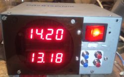
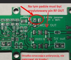
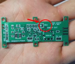
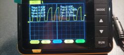
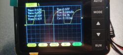
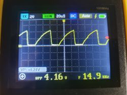
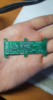
A simple but effective 2.4 GHz jammer. This module can block BT and Wi-Fi. I designed it so that the cost of its implementation was as low as possible due to the semiconductor crisis. The circuit includes a simple astable multivibrator with a square wave to saw converter for generating the VCO control signal. The 5.1V power supply is provided by the MT3608L converter, so the device can be powered by any LiPo battery, but please make sure the battery can supply at least 500mA of current, if you want to use the amplifier, the current must be at least 1A. The VCO generates the sweep signal in the range 2100-2600 MHz. The output power is about 5-10mW, you can use an amplifier if you want more range. The CHRG fields are used to charge the battery, the 5V out pad is used to connect an external device, e.g. an amplifier. The SWEEP OUT pad is used to calibrate the output wave, the ADJ potentiometer adjusts the waveform, the correct signal should look something like this:
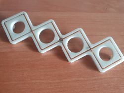
To emit a signal, a biquad antenna works best, I attach a link with an interesting article on how to make it and a model for printing a 3d antenna frame
https://buildyourownantenna.blogspot.com/2014...-biquad-sector-antenna-for-2450-mhz-wifi.html
3D printing model: https://www.thingiverse.com/thing:4734227
To disrupt the signal, point the jammer at the receiver, remember that the effectiveness of the interference depends on the distance between the transmitter and receiver. When the phone is 20 cm from the loudspeaker, jamming is almost impossible, but when the phone is 2 m away, the jammer can easily block the signal within a range of several to several meters.
An example of a 1W amplifier: https://pl.aliexpress.com/item/10050023541036..._list.0.0.37e01c24IXT8Uk&gatewayAdapt=glo2pol
Cheaper 100 mW amplifier: https://a.aliexpress.com/_EJz6Zs5
VCO used: https://pl.aliexpress.com/item/1005002503822581.html
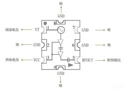
You can use a model other than YSGM232508, such as SV2450 or SM2400, the pinout should look like this:
Schematic diagram:

Tile appearance:
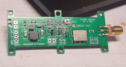
Assembly diagram:

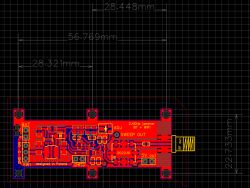
Mounting holes spacing:
In the attachments I include the GERBER file to order the board and the list of materials (BOM), if, for example, you want a PDF file for etching or purchase a printed circuit board (boards sold out!), I invite you to a private chat.
Please remember that interference with Wi-Fi or bluetooth is illegal, a device for private use only to block, for example, spy devices (webcam, listening loudspeaker). The author is not responsible for improper use of the jammer, post and the information contained therein solely for educational purposes.

To emit a signal, a biquad antenna works best, I attach a link with an interesting article on how to make it and a model for printing a 3d antenna frame
https://buildyourownantenna.blogspot.com/2014...-biquad-sector-antenna-for-2450-mhz-wifi.html
3D printing model: https://www.thingiverse.com/thing:4734227

To disrupt the signal, point the jammer at the receiver, remember that the effectiveness of the interference depends on the distance between the transmitter and receiver. When the phone is 20 cm from the loudspeaker, jamming is almost impossible, but when the phone is 2 m away, the jammer can easily block the signal within a range of several to several meters.
An example of a 1W amplifier: https://pl.aliexpress.com/item/10050023541036..._list.0.0.37e01c24IXT8Uk&gatewayAdapt=glo2pol
Cheaper 100 mW amplifier: https://a.aliexpress.com/_EJz6Zs5
VCO used: https://pl.aliexpress.com/item/1005002503822581.html
You can use a model other than YSGM232508, such as SV2450 or SM2400, the pinout should look like this:

Schematic diagram:

Tile appearance:


Assembly diagram:

Mounting holes spacing:

In the attachments I include the GERBER file to order the board and the list of materials (BOM), if, for example, you want a PDF file for etching or purchase a printed circuit board (boards sold out!), I invite you to a private chat.
Please remember that interference with Wi-Fi or bluetooth is illegal, a device for private use only to block, for example, spy devices (webcam, listening loudspeaker). The author is not responsible for improper use of the jammer, post and the information contained therein solely for educational purposes.
Cool? Ranking DIY


