What microcontroller powers the NAS-SC01W series?
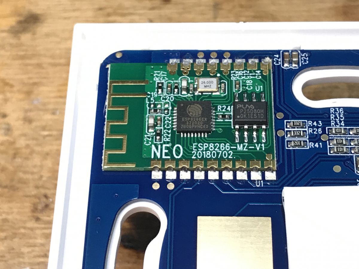
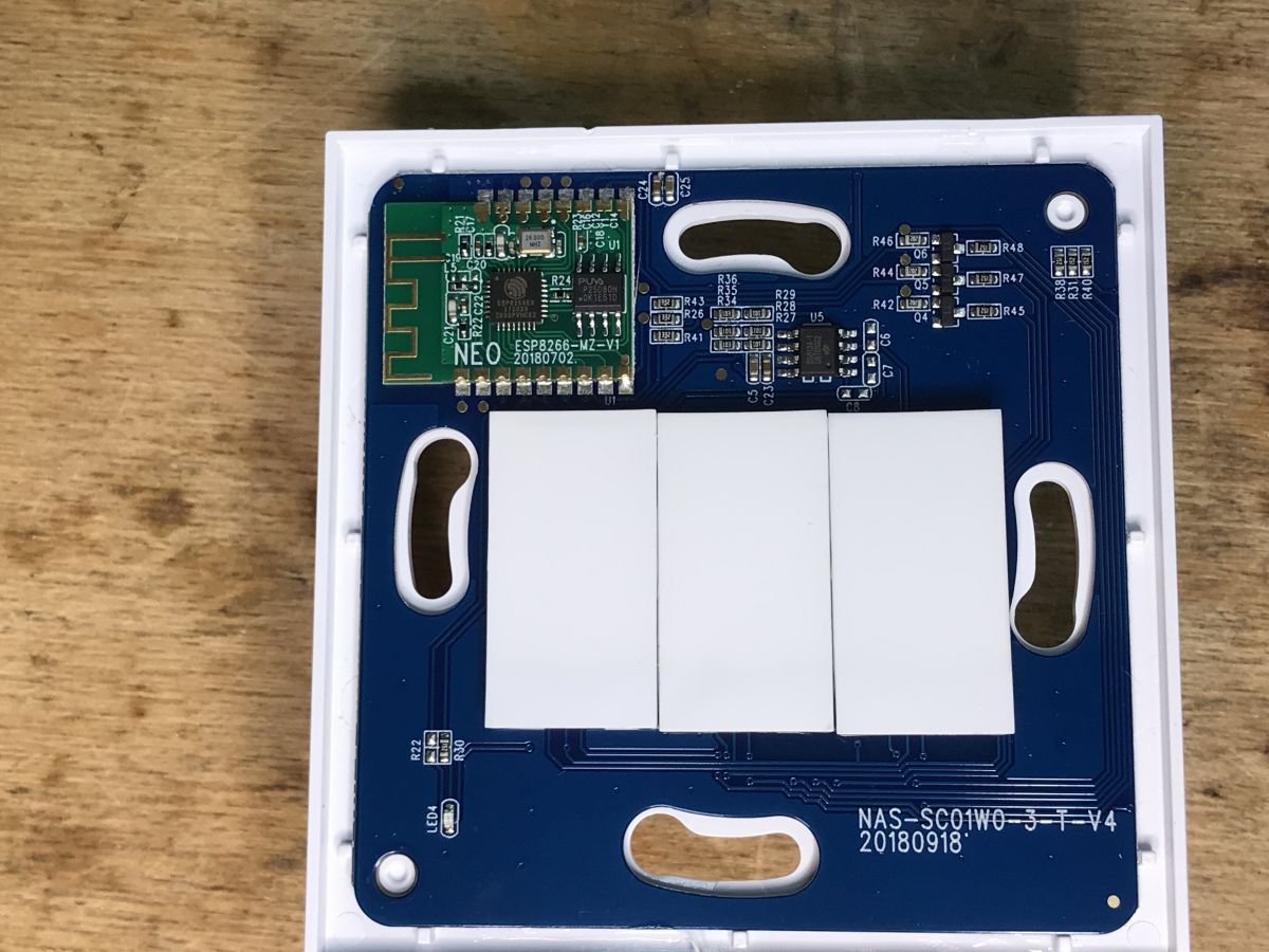
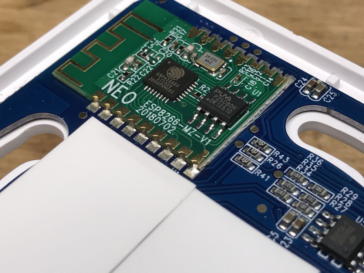
All NAS-SC01W-1/2/3 switches use an ESP8266-MZ-V1 module, dated 2018-07-02 [Elektroda, p.kaczmarek2, post #20280388]
Czy wolisz polską wersję strony elektroda?
Nie, dziękuję Przekieruj mnie tam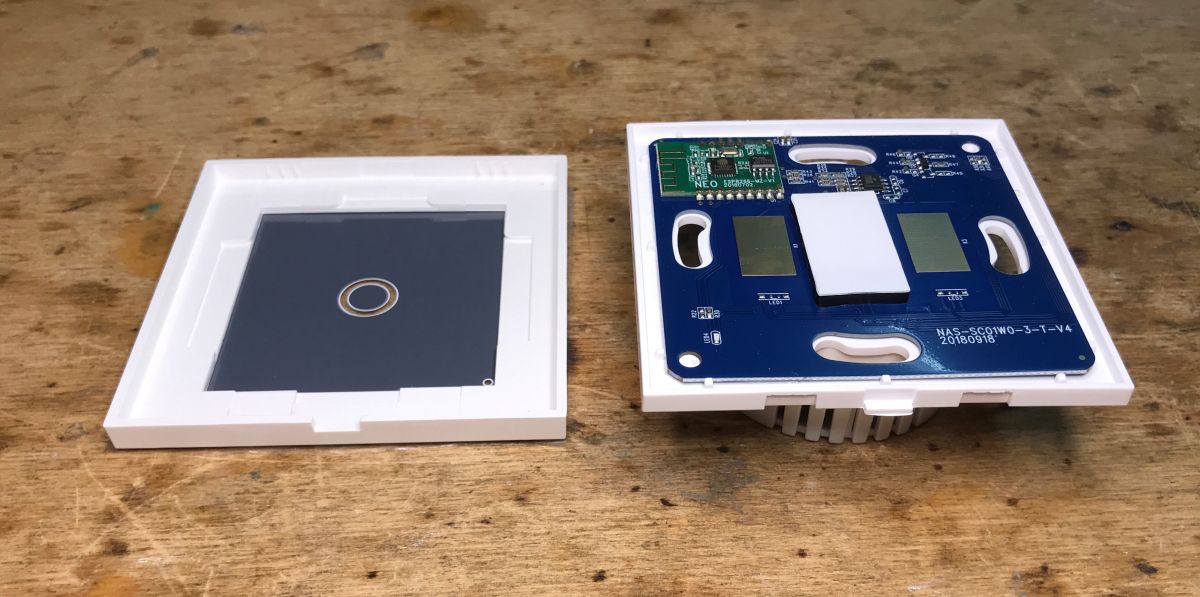
Quote:
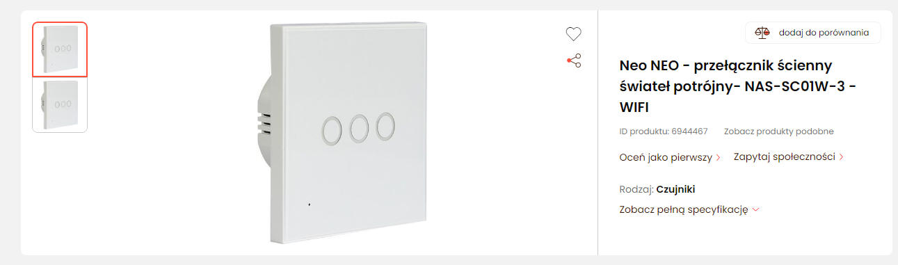
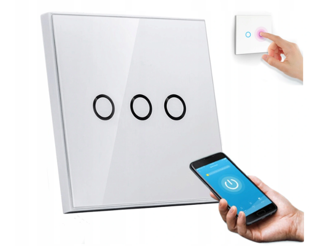
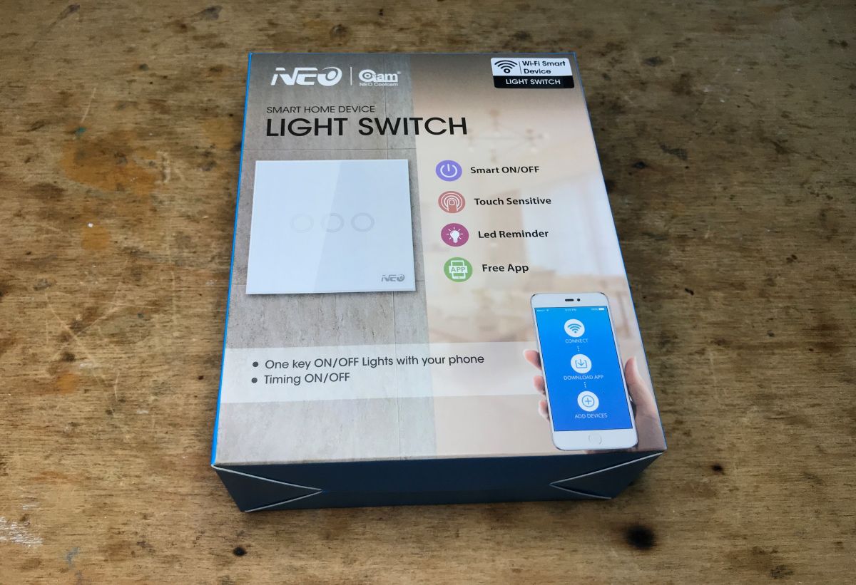
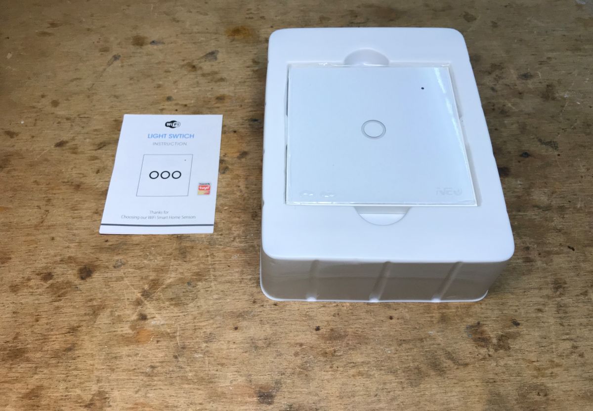
- Touch panel made of tempered glass
- Wireless operation on WIFI network
- No delay in operation
- Control of one circuit
- Range up to 40m from router
- LED indication of channel status
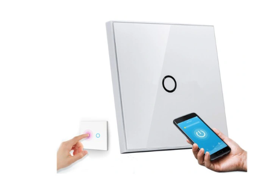
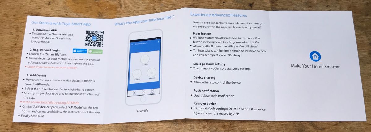
- Free TUYA app for iOS and Android
-. Ability to create scenes with the switch
- Ability to set a schedule
- Ability to work with GOOGLE assistant
- Ability to work with AMAZON ALEXA
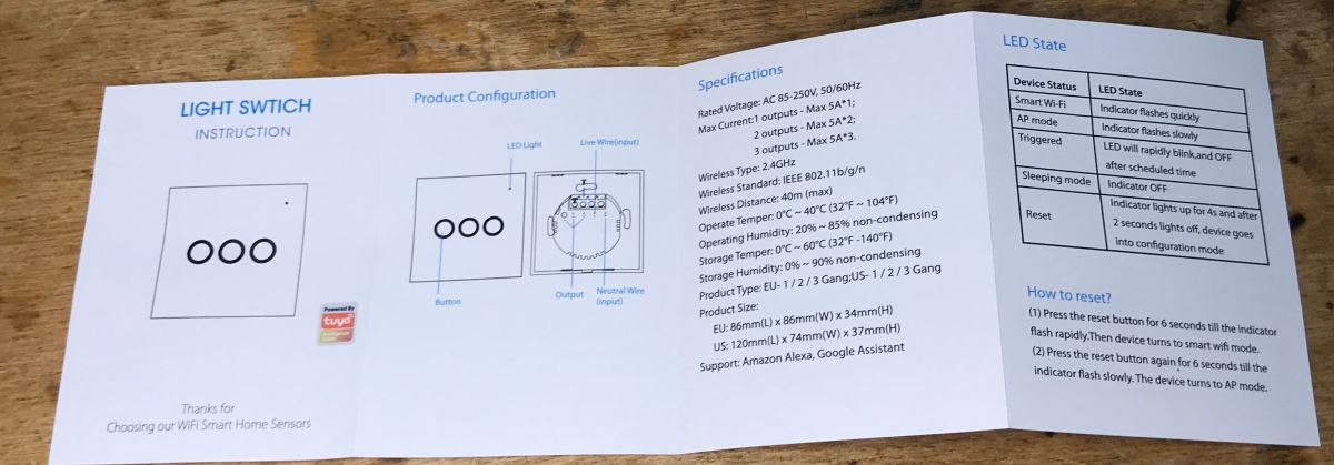
- Compact shape and excellent workmanship
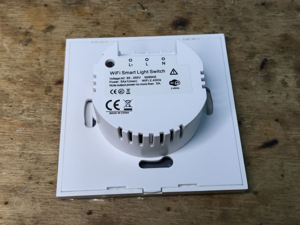
 Interior NAS-.SC01W-1 We remove the cover and see the ESP8266-MZ-V1 dated 20180702. You can upload Tasmota, although I don't know what is in the same switches but produced after 2018 or, for example, in 2022....
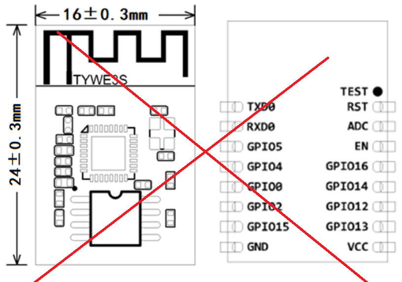
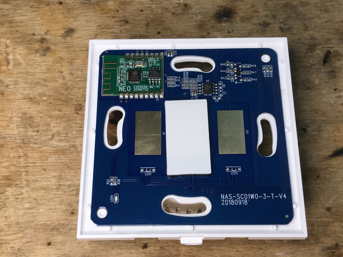 Only now a note - this module has no leads compatible with TYWE3S, or there with ESP12F, ESP12E .
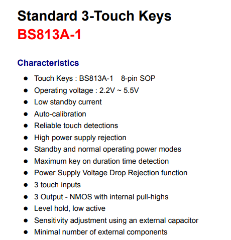
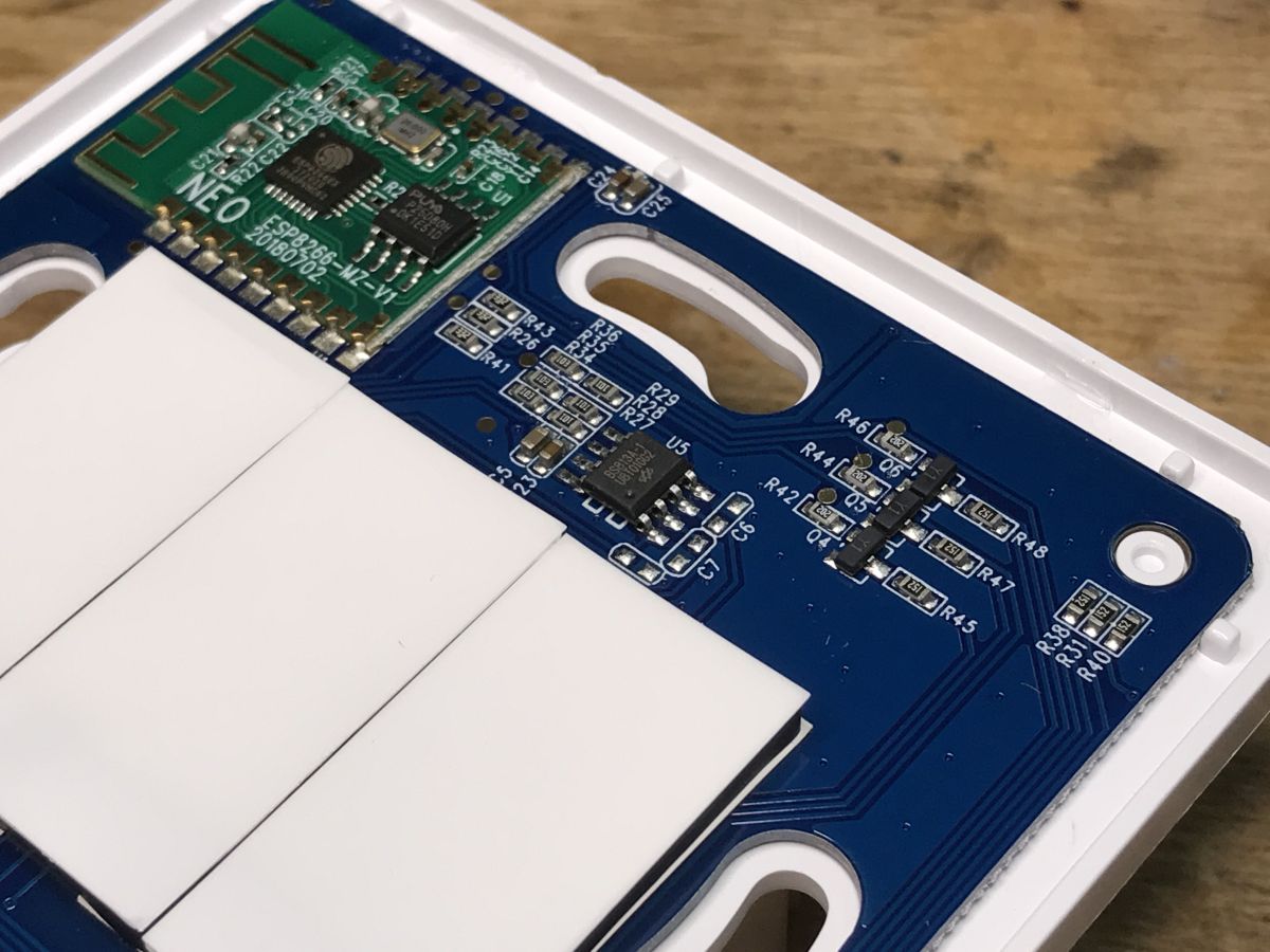
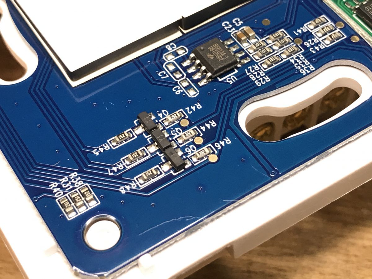
 BS813A is a touch button controller, production of Holtek.
 8cb911fbb
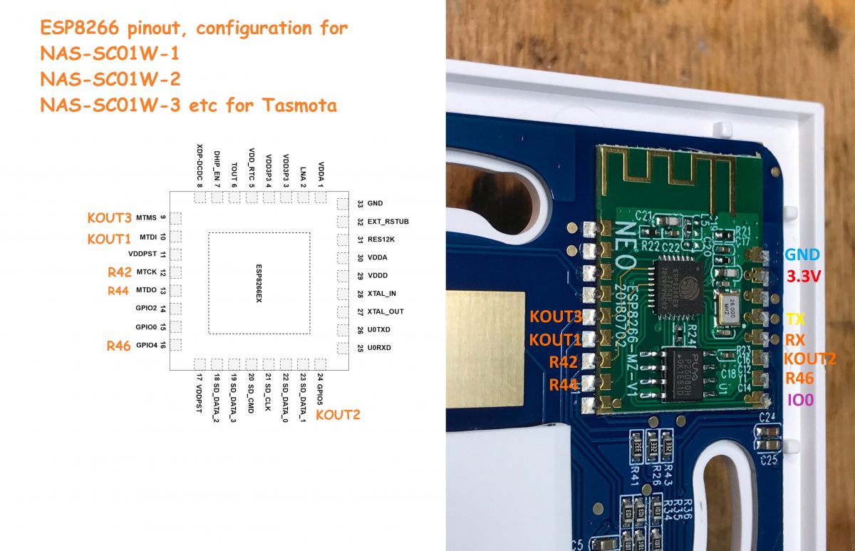 For programming, use 3.3V, GND and TX, RX and IO0 marked on the picture! All as, among others. here:
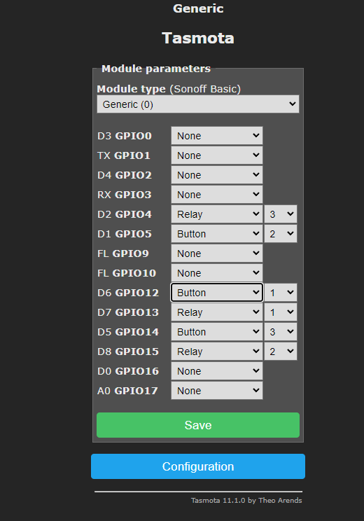
| Role | [td] Pin ESP |
| Button 1 | [td] MTDI/GPIO12 (10) |
| Button 2 | GPIO5 (24) |
| Button 3 | MTMS/GPIO14 (24) |
| Transmitter 1 | MTCK/GPIO13 (12) | [/td]
| Transmitter 2 | MTDO/GPIO15 (13) |
| Transmitter 3 | GPIO4 (16) |
| LED WiFi | XDP-.DCDC/GPIO16 (8) |
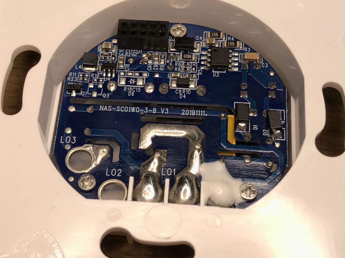
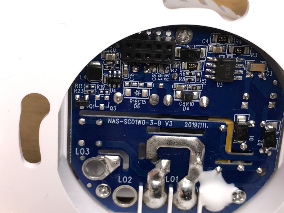
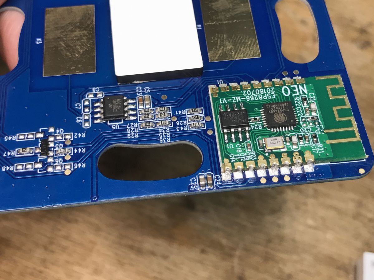
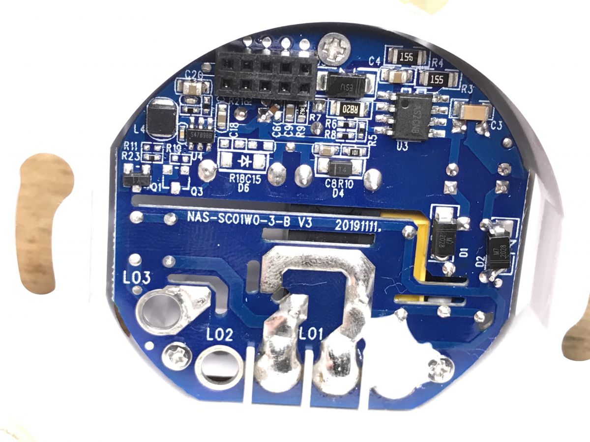 From what I can see, the power supply here is on ASZCNB (decipher anyone?) in SOIC8, the relay turns on Y1, and the 3.3V is provided by S47B9BB.

TL;DR: NAS-SC01W touch switches cost about 100 PLN (~25 USD) and claim "up to 40 m Wi-Fi range" [Elektroda, p.kaczmarek2, post #20280388] "UART lines are not busy" for easy flashing [Elektroda, p.kaczmarek2, post #20280388] Why it matters: You can re-use these ESP8266-based wall switches for custom smart-home projects without soldering.
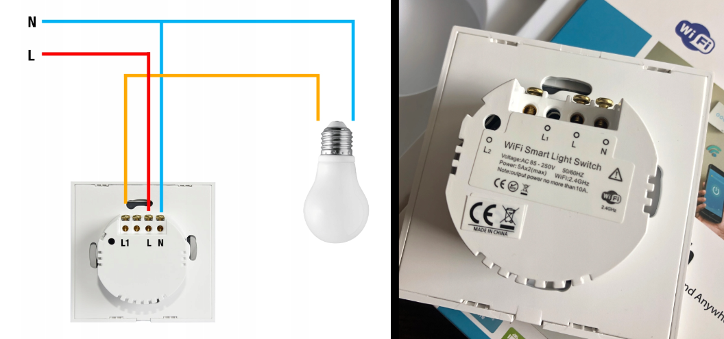
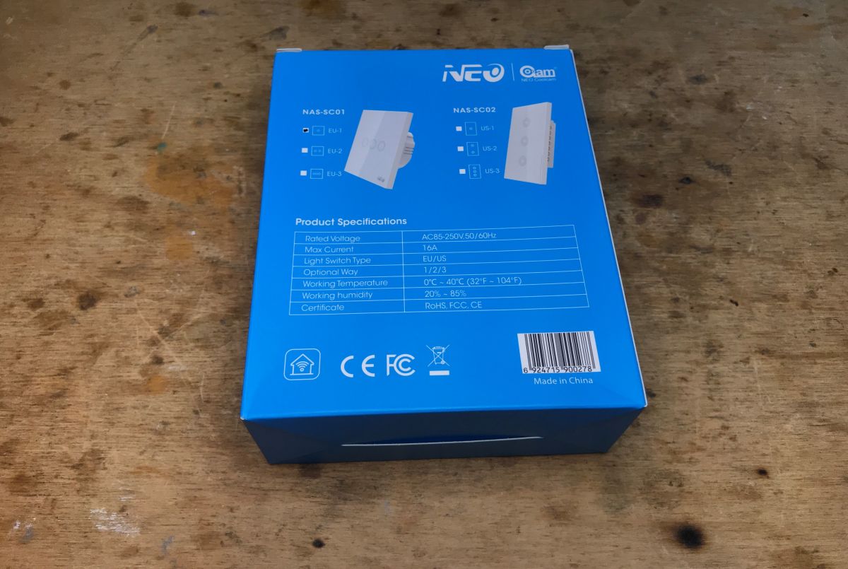
• MCU: ESP8266-MZ-V1, 2 MB flash [Elektroda, p.kaczmarek2, post #20280388] • Supply: 100–240 VAC input; on-board 3.3 V LDO (S47B9BB) [Elektroda, p.kaczmarek2, post #20280388] • Dimensions: 86 × 86 × 34 mm [Elektroda, p.kaczmarek2, post #20280388] • Claimed Wi-Fi range: ≤40 m @ 2.4 GHz [Elektroda, p.kaczmarek2, post #20280388] • Street price: ~25 USD per gang [Elektroda, p.kaczmarek2, post #20280388]
Comments
Out of curiosity, would it give to upload this regular arduino and e.g. use some unused pin e.g. for temp measurement? [Read more]
You can easily program it through a regular Arduino or PlatformIO and that with a bootloader over WiFi and do whatever you want with the pins. I once even described it with Arduino IDE: https://www.elektroda.pl/rtvforum/topic3749207.html... [Read more]