A while back I posted the teardown and OpenBK configuration of the Cool/Warm White only version which can be found
here. Finally I gotten around to flash the RGB variety of these downlights.
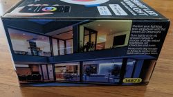
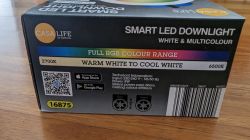
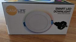
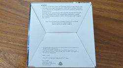
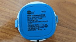
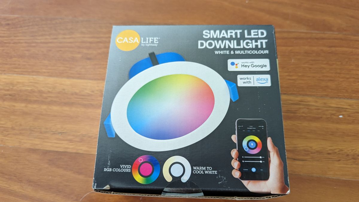
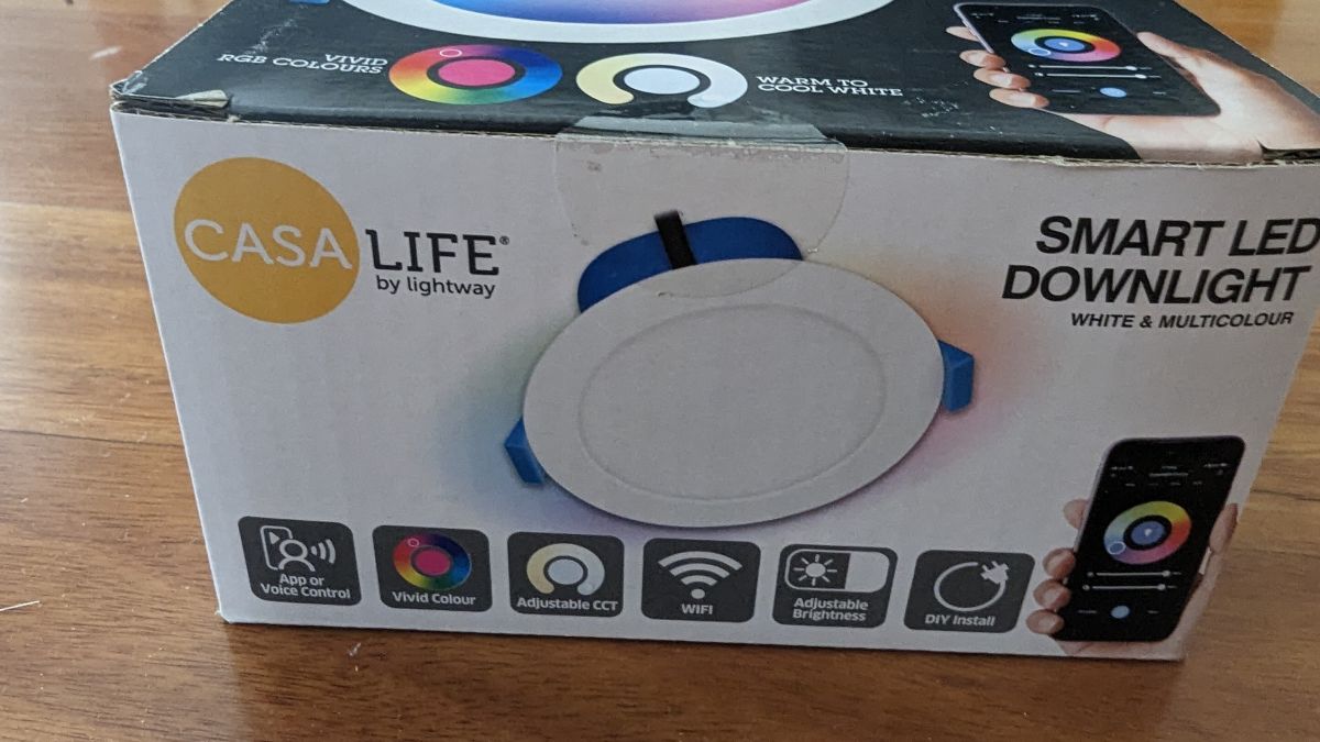
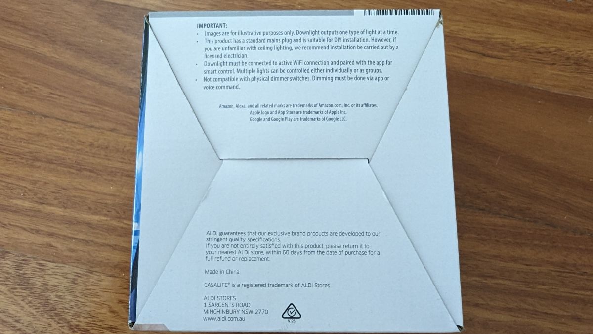
Starting with the pictures of the box:


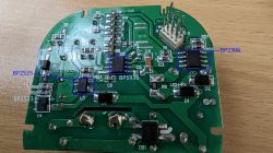
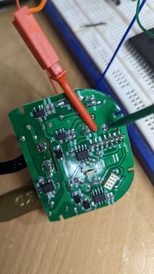
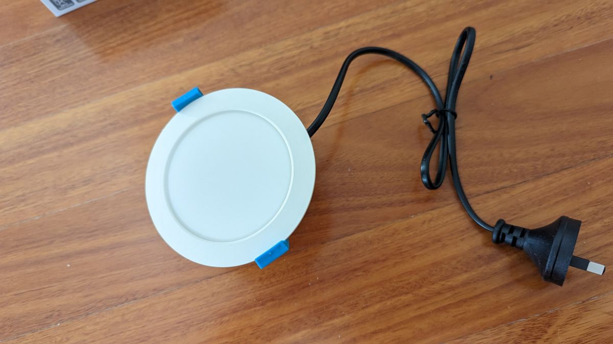
 Pictures of the device:

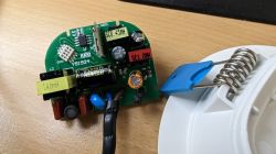
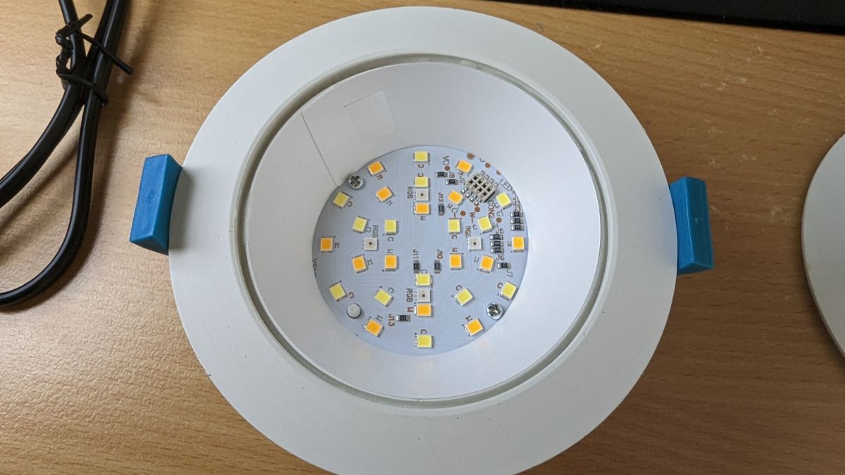
 Opening up:
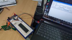
 Flashing:
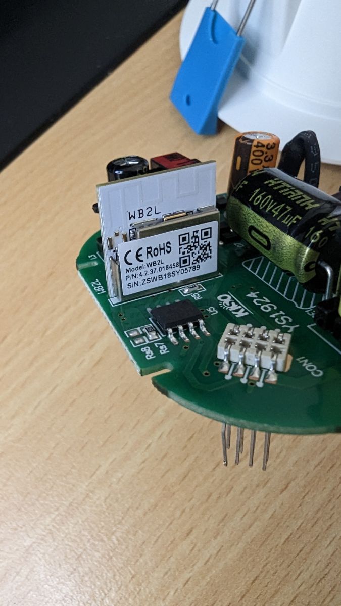
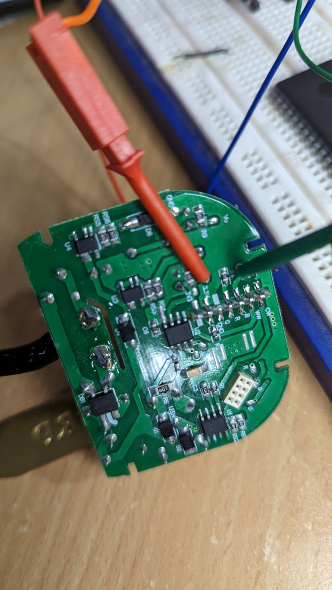
I dreaded the thought of having to de-solder the chip, soldering the flashing wires, re-soldering, and then multiply that 20 times!! So I attempted a no solder method which actually worked.
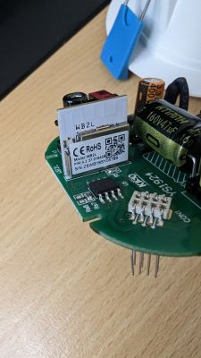
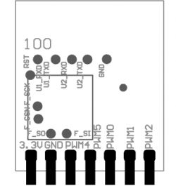
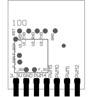
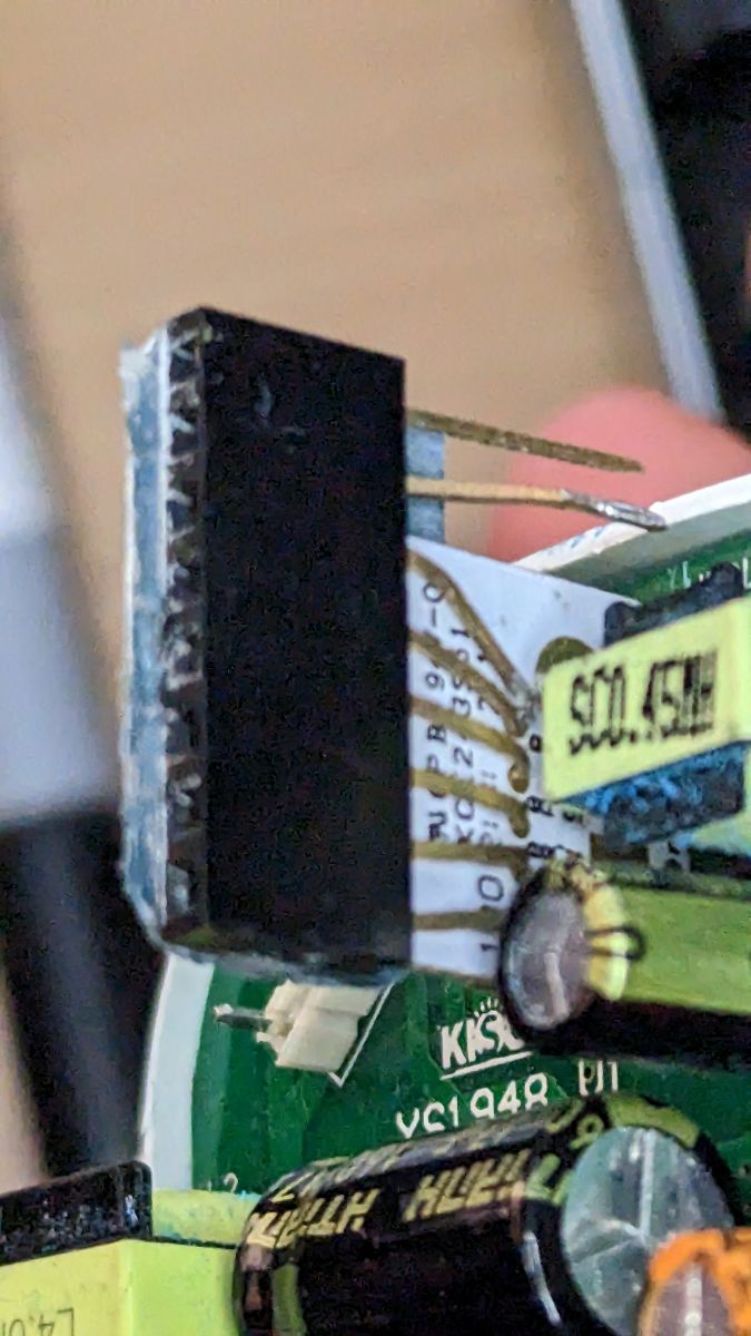
First I built a connector for the 4 pads on the WB2L module corresponding to the 2 UART interfaces lined up at the top of the module.
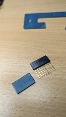
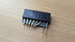
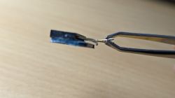
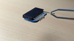

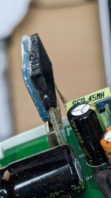
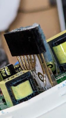
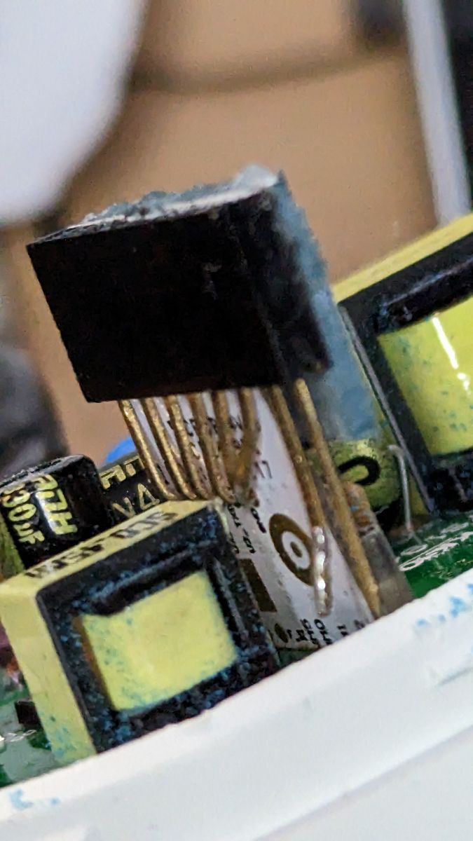
I took an 8 pin header left over from another ESP controller, and super-glued a piece of plastic to one side, and bent the pins of the header in such a way that it lined up with the appropriate pads, but also the springiness of the metal clamps the connector to the WB2L module.
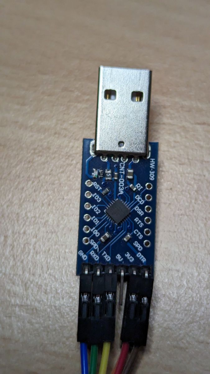
The UART-USB interface I used was CP2104, it is a good idea to leave the 5v pin disconnected, and can connect the ground pin and 3.3v to the convenient points located at the back of the board using a mini probe.

* The flasher I used was
BK7231GUIFlashTool.
* Before flashing it is a good idea to first hook up the UART-USB to UART2 and use Putty to confirm that the pins from the connector have good contact, and the UART interface is supplying enough current at 3.3v to power the WB2L module.
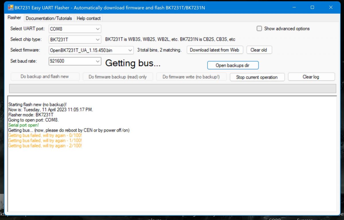
Flash Sequence:
1. Connect up the UART-USB interface to UART1 on the WB2L module, and the ground pin. Leave the 3.3v disconnected for now
2. Start the firmware write on the flasher tool and observe the "Getting bus..." message.
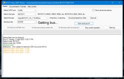
3. Connect the 3.3v to the WB2L module and observe flash write progressing.
4. Once the flash completes, connect to the open access point, navigate to 192.168.4.1 and update the wifi credentials, as per previous instructions.
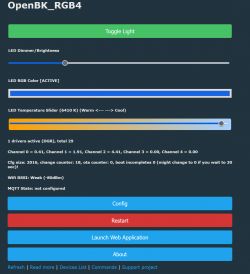
Configuring:
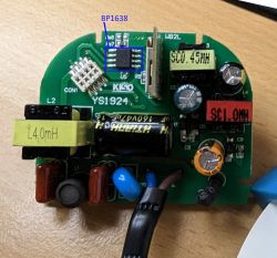
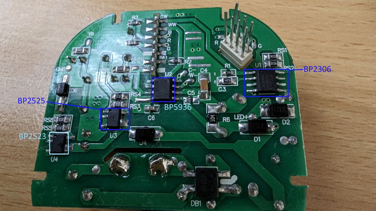
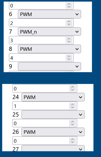
Here is the pin configuration:
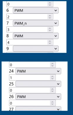
RED - CH0: PIN26: PWM
GREEN - CH1: PIN24: PWM
BLUE - CH2: PIN6: PWM
C/W TEMP - CH3: PIN7: PWM_n
C/W BRIGHTNESS - CH4: PIN8: PWM
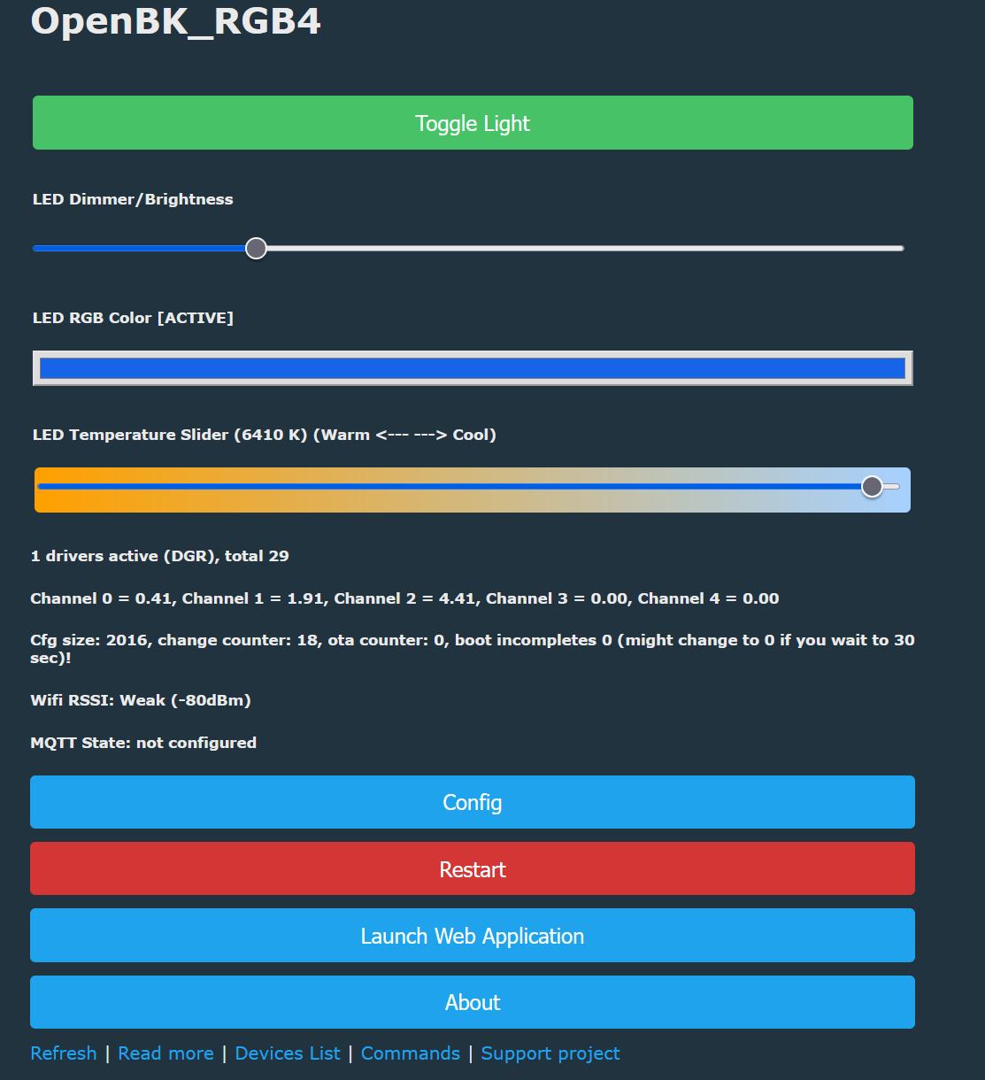
As with the CW white downlight version, the PWM channels control the temperature and brightness directly. Therefore the "Flag 8 - [LED] Alternate CW light mode (first PWM for warm/cold slider, second for brightness)" should be enabled in the Configure General/Flags section.
If all goes well you should see the RGB controller on the main page.
 Added after 18 [minutes]:
Where do I post the template:


Comments