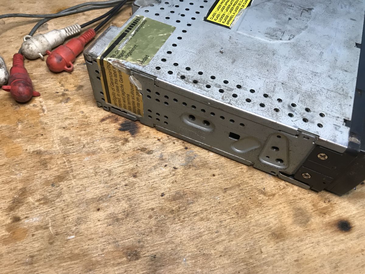
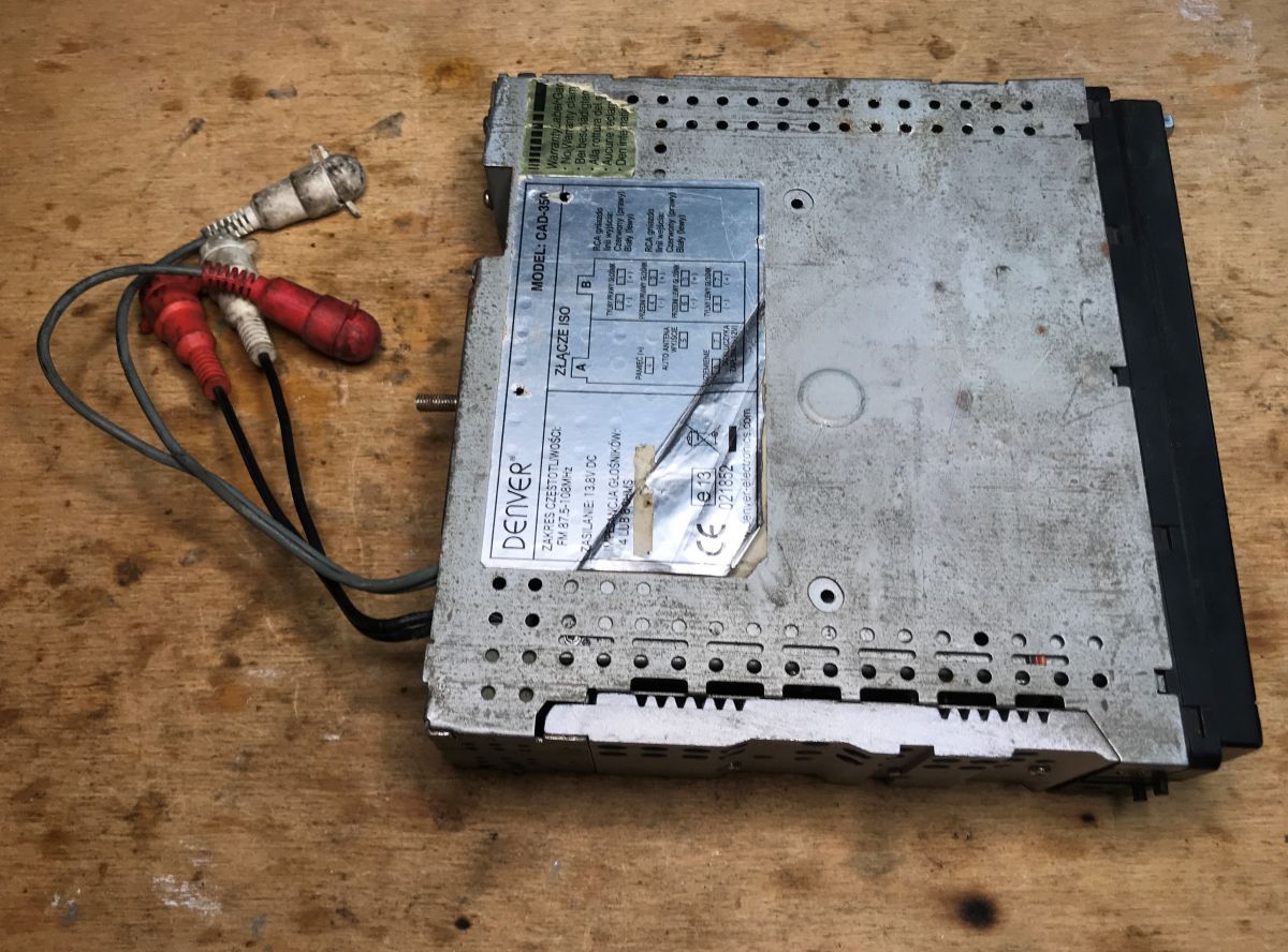
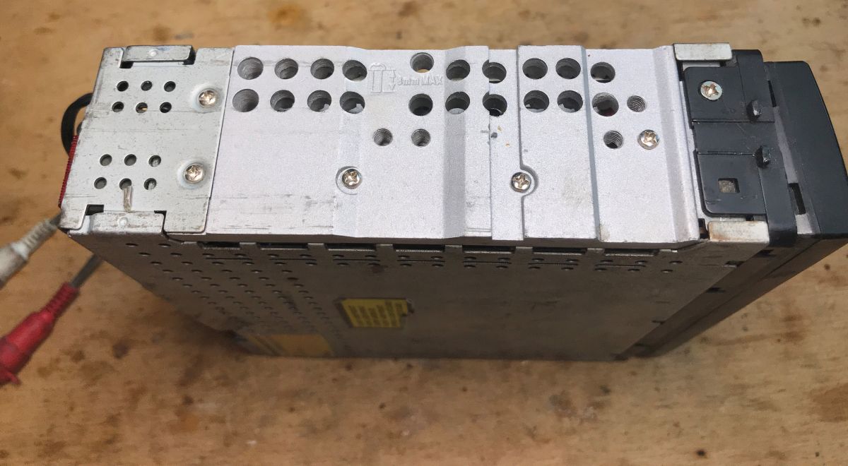
A Denver CAD-350 car radio was dismantled to recover its LCD panel and PT6523 controller for Arduino-driven experiments.
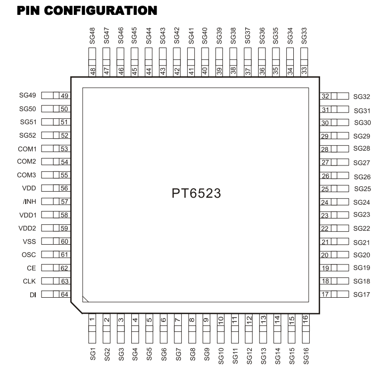
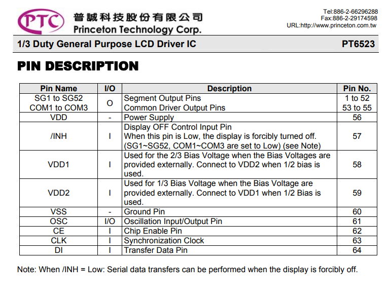
The display uses a simple serial interface—DI, CLK, CE and INH—while the controller also has an RC oscillator and LCD power decoupling on the module.
The radio’s schematic shows the PT6523 SPI lines through 680 ohm resistors with 33pF capacitors to ground, and the backlight runs from 12V.
Using a GitHub PT6523 library, the LCD powered up correctly, showed text and symbols without segment mix-ups, and the module was trimmed into a compact breakout.
The main limitation is the need to preserve ground connections when cutting the PCB and to add a separate 12V step-up for the backlight.
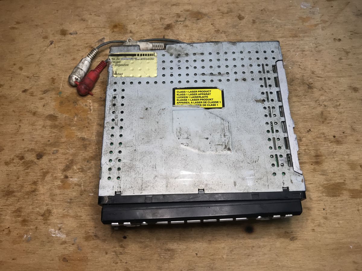
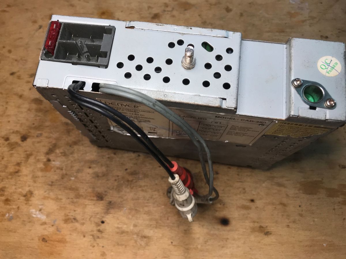
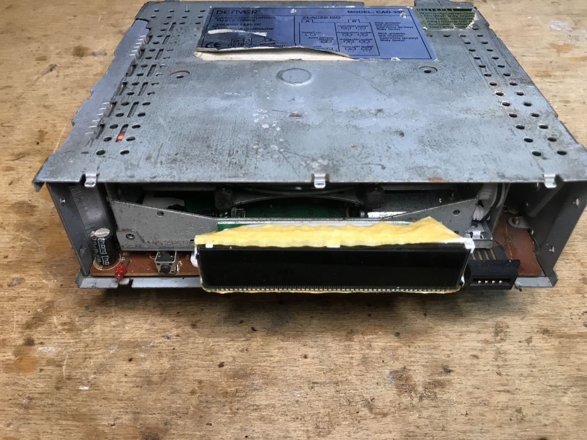
Interior of Denver CAD-350 . It's time to take a closer look at what I was able to find this time. Denver car radio, capable of receiving FM 87.5-108MHz and playing music from disc. The sticker describes the connections to the ISO connector.
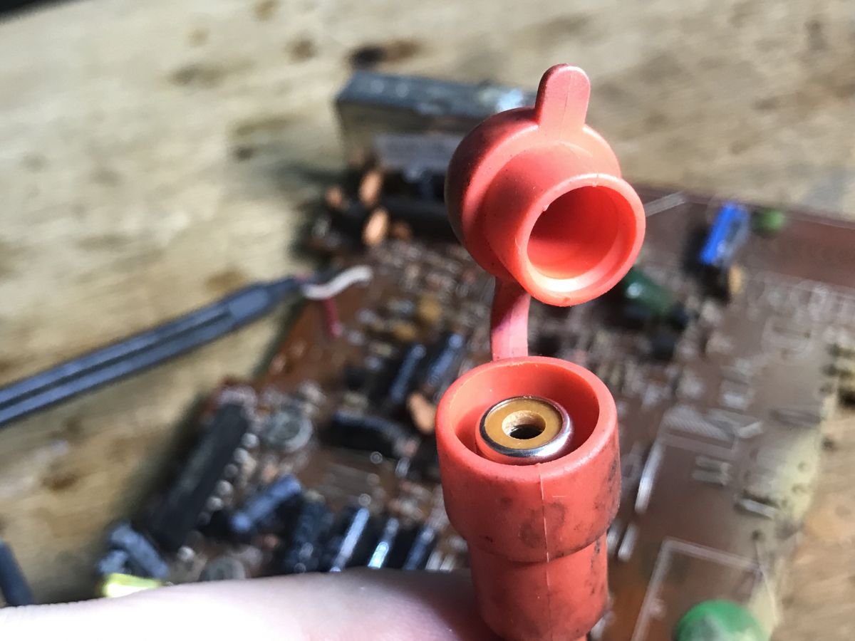
. These connectors on the back are RCA:
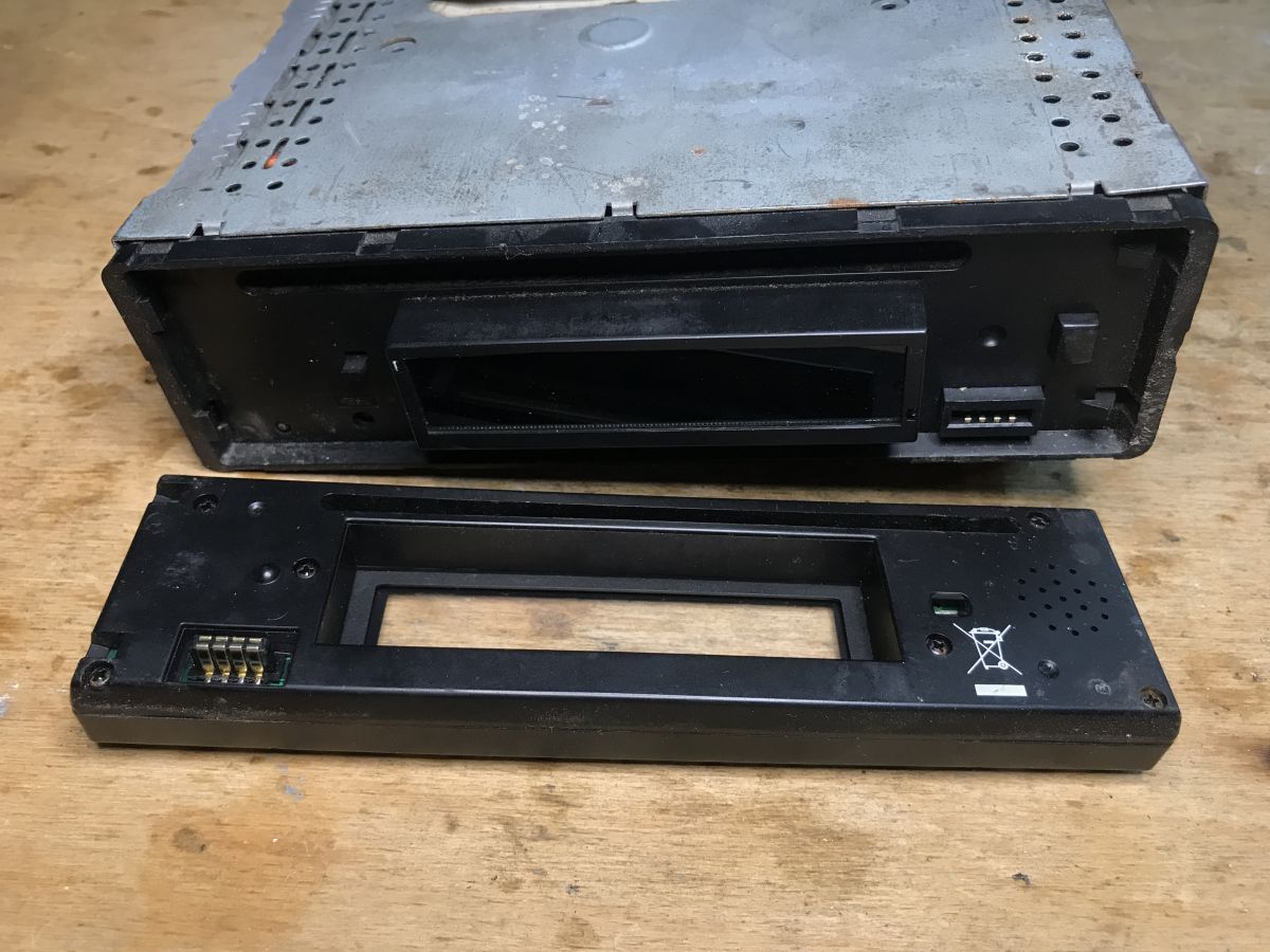
The front is removable, I don't know why they were designed that way. Maybe someone sitting in the "car" will explain it.
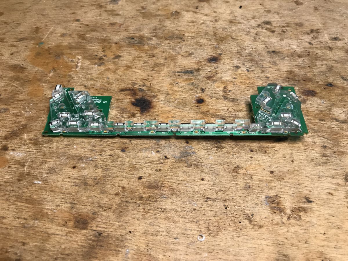
The panel with buttons and LEDs is rather not interesting to us: We continue unscrewing the case, we can already see the LCD display:
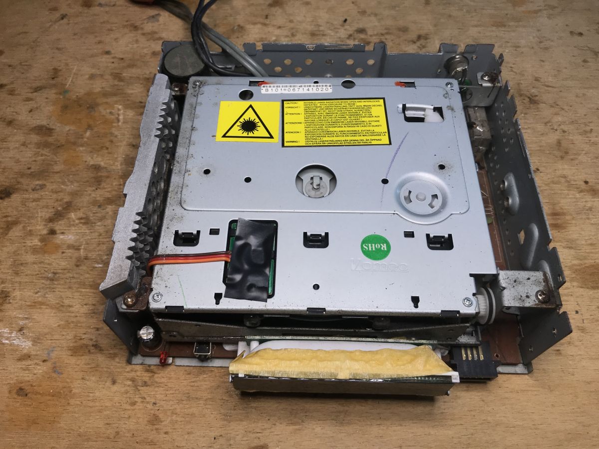
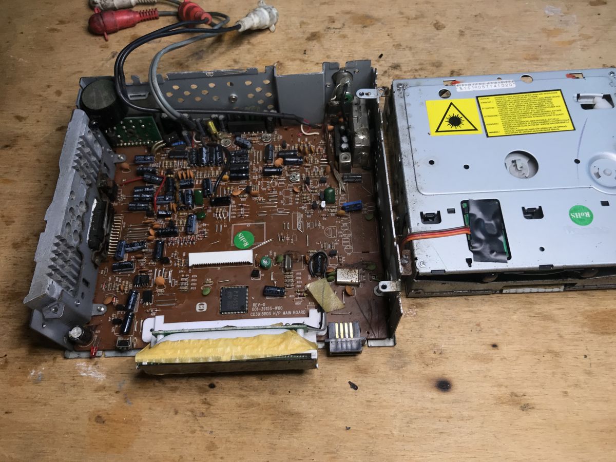
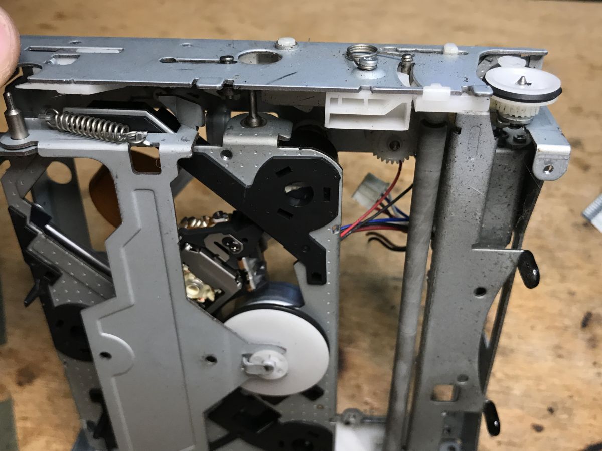
Inside of the radio:
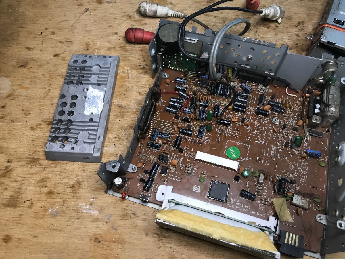
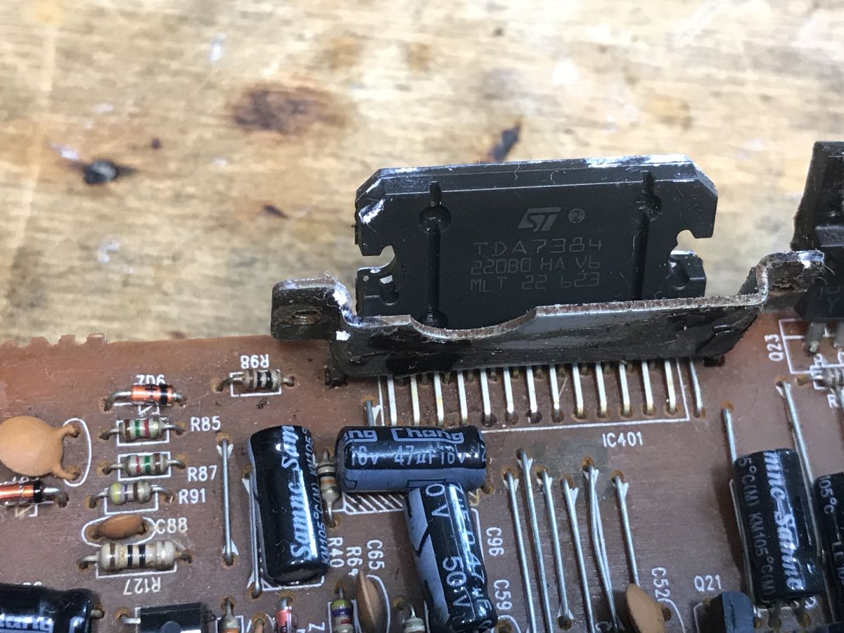
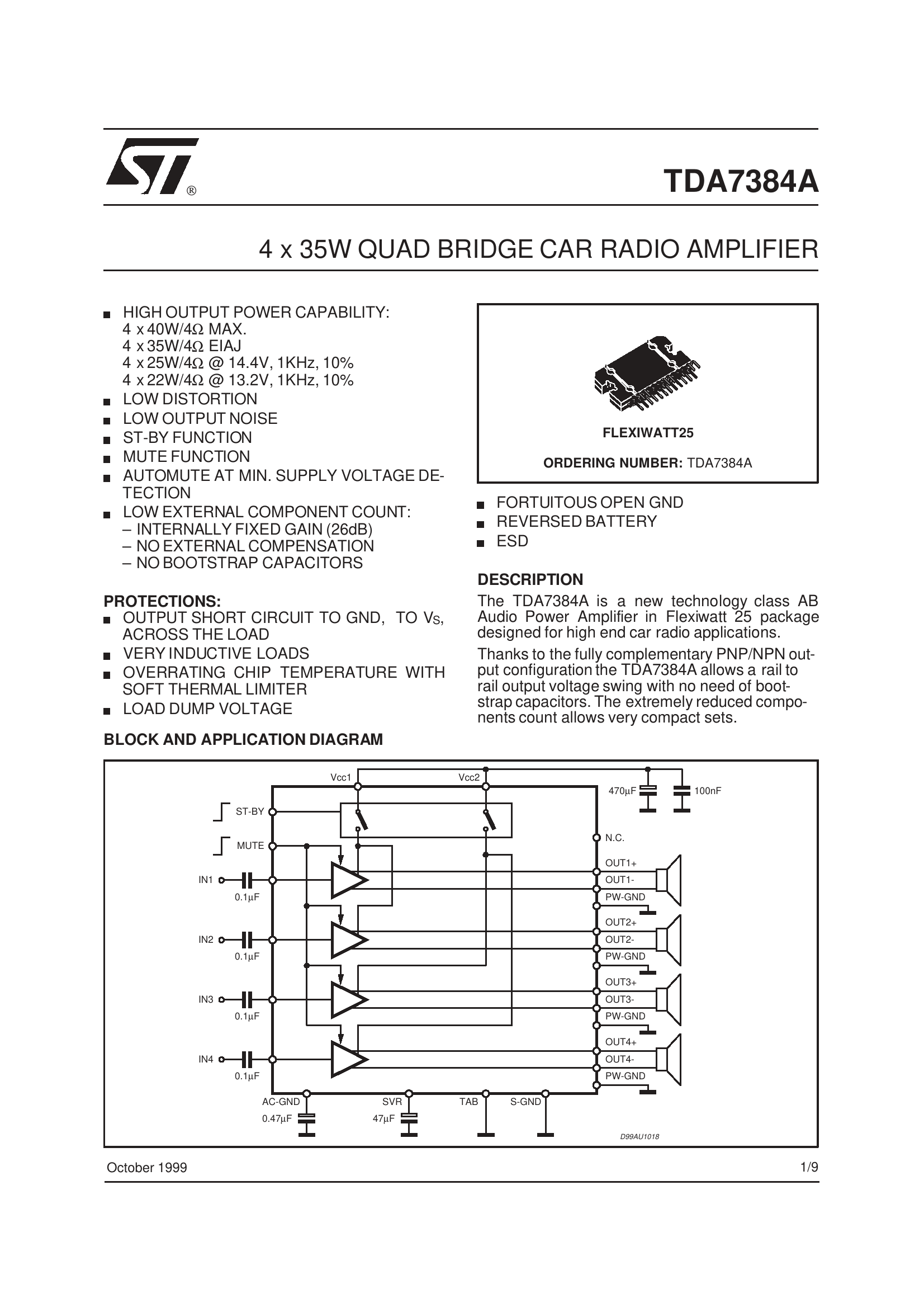
Dismantling the heatsink from the audio amplifier: From what I can see, the TDA7384 is playing here:
4x35W, this must have played pretty well:
This could be used for DIY, but I'm not as interested in audio as I am in, for example. microcontrollers.
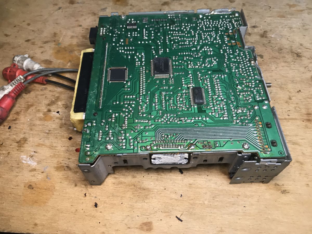
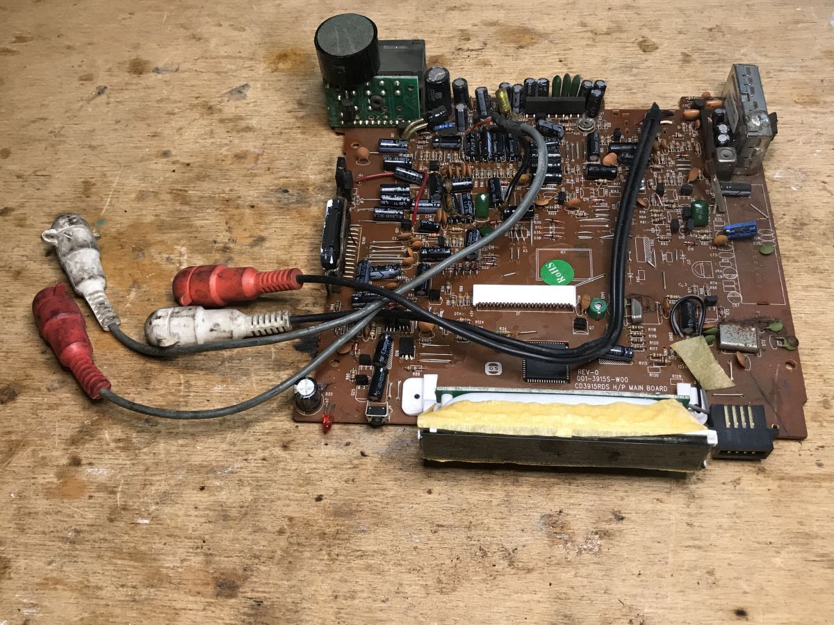
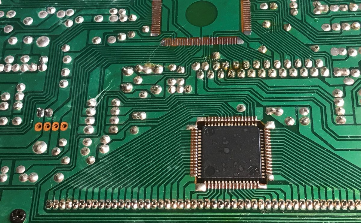
A glance at the underside of the PCB shows us that virtually everything here is THT-mounted, with only a few major ICs surface-soldered:
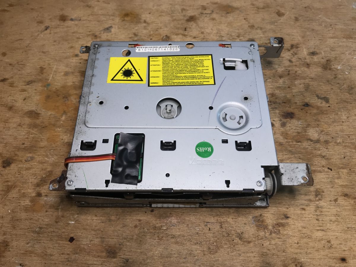
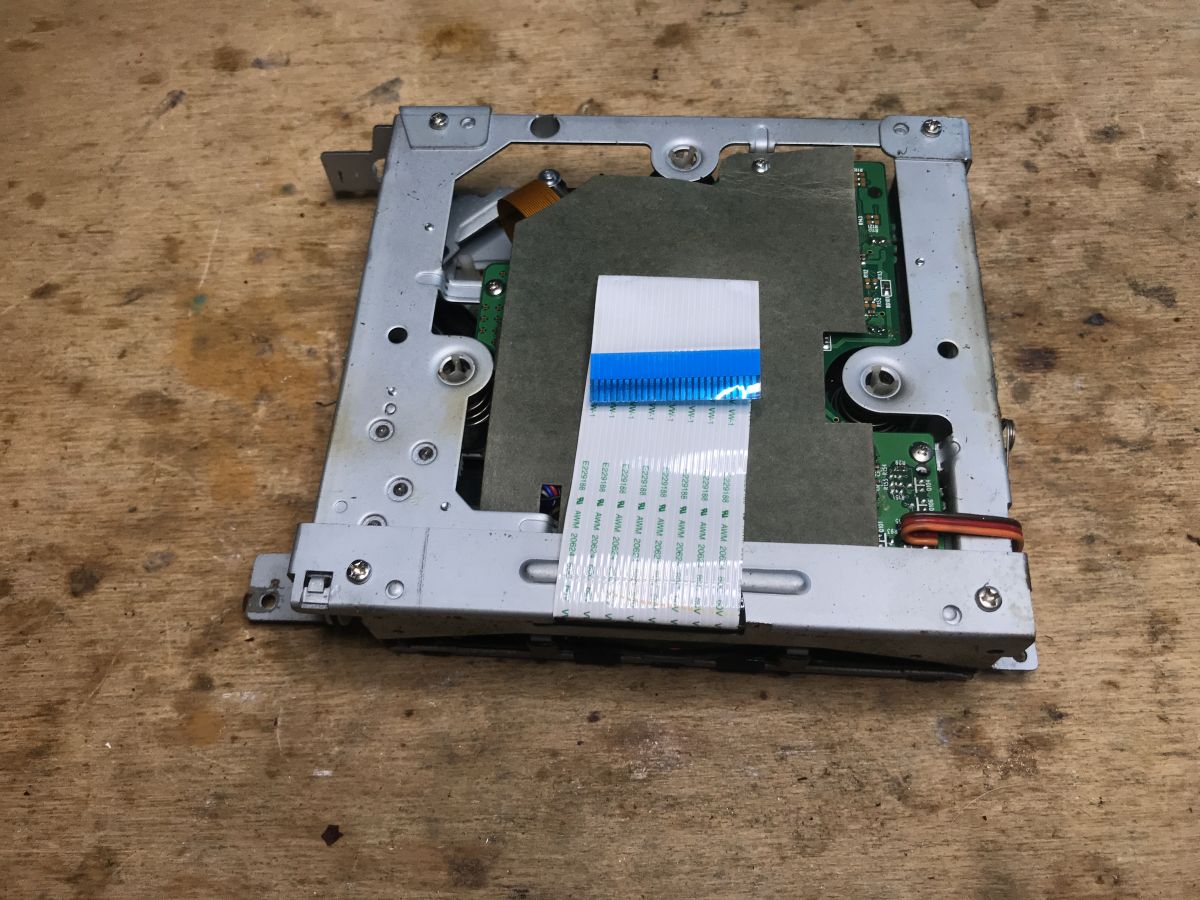
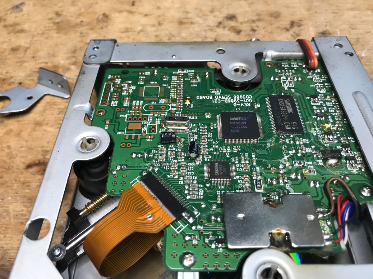
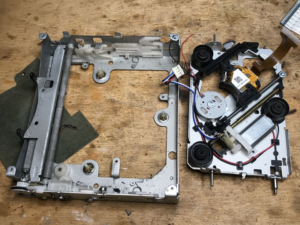
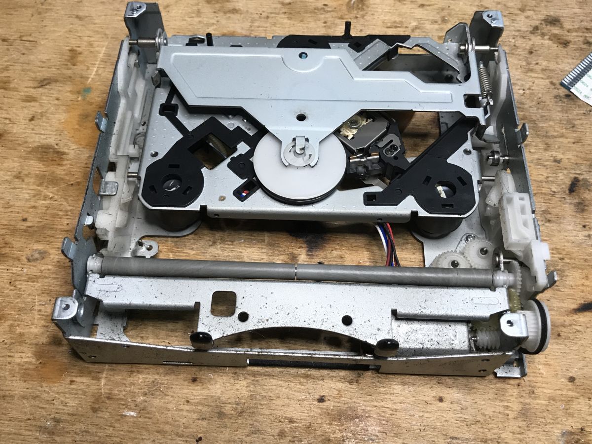
Let's take a moment for the CD player :
Samsung 9226X01 and S5L8310W, the chips themselves designed for the CD player. Nothing interesting. The K4S161622H, on the other hand, is an SDRAM, but we're not likely to find it useful either. Too many lines are needed to "talk" to it. More cool are Flash and EEPROM memories which can be found in monitors, often in SO8 cases, or there those from older TVs, still in DIP8, with I2C or SPI interfaces.
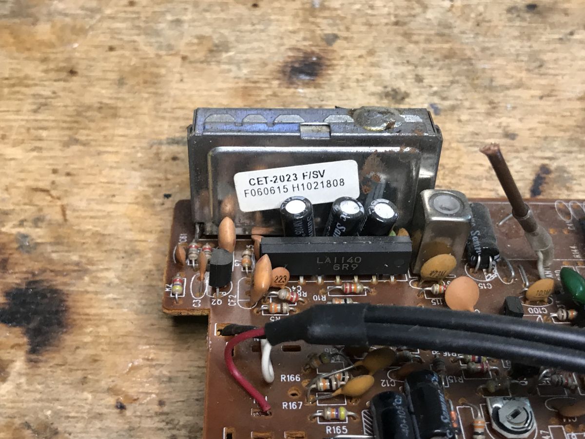
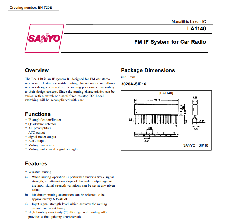
Sometimes you can also remove a fairly powerful laser diode from them, but that's from DVD recorders, here I'd rather not count on one. Rather nothing useful. Back to the rest of the radio. This is what the PCB freed from the inside looks like: By the FM head I see LA1140, the IF (intermediate frequency) handling circuit:
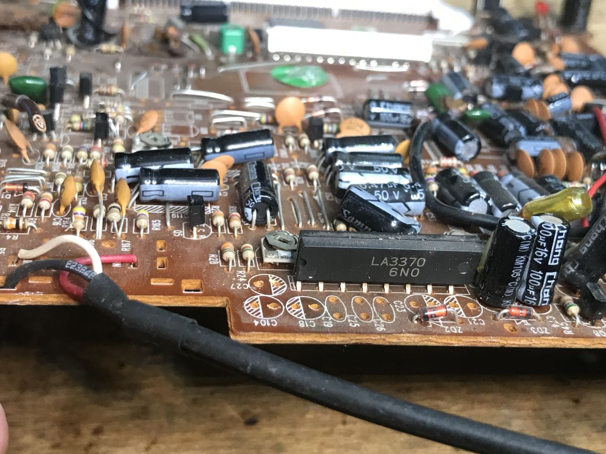
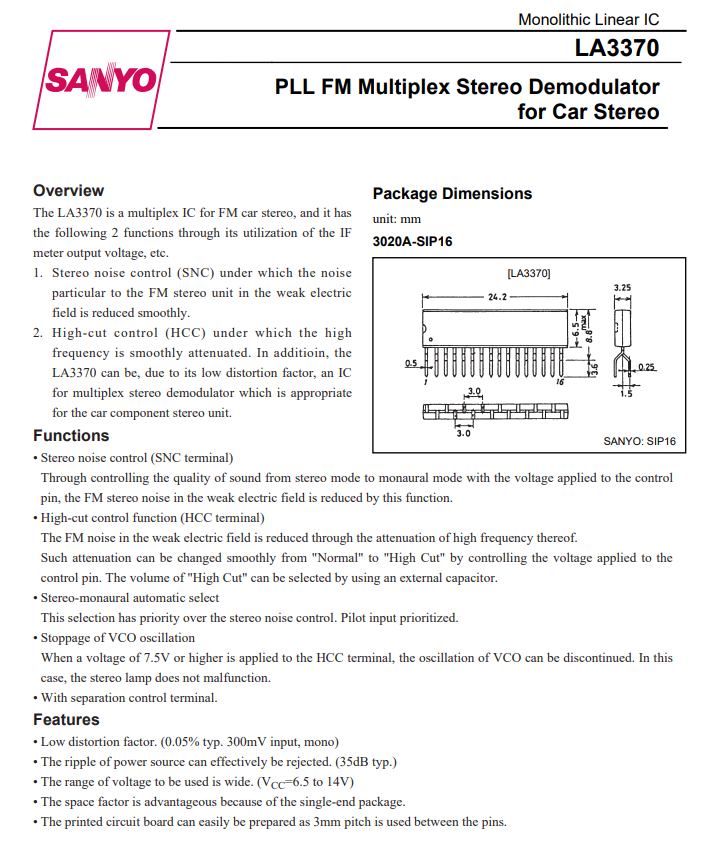
On the edge of the PCB, covered by capacitors is a related circuit, also from audio, LA3370, PLL FM Multiplex Stereo Demodulator:
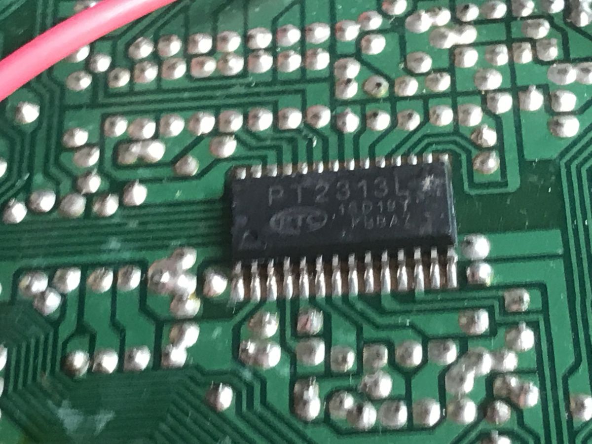
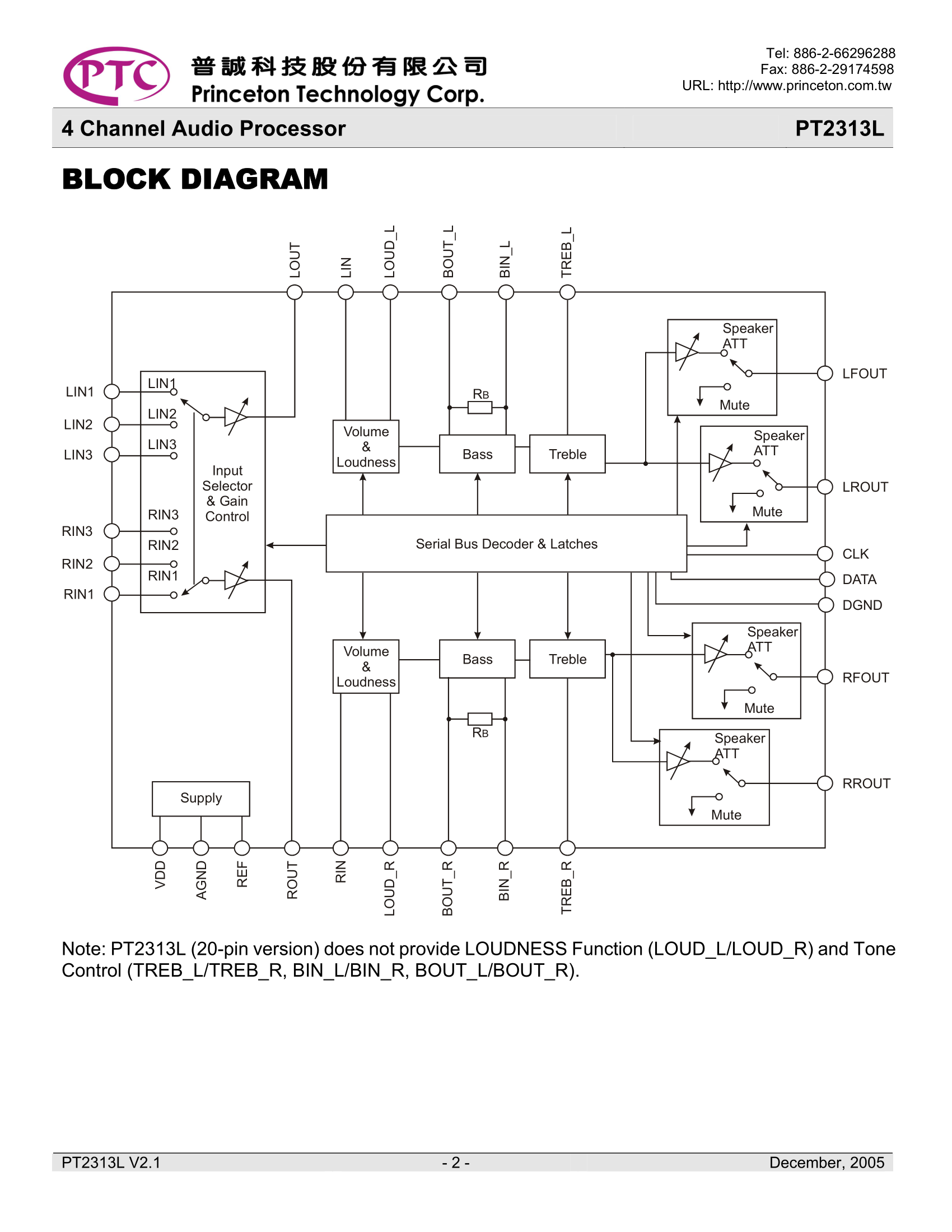
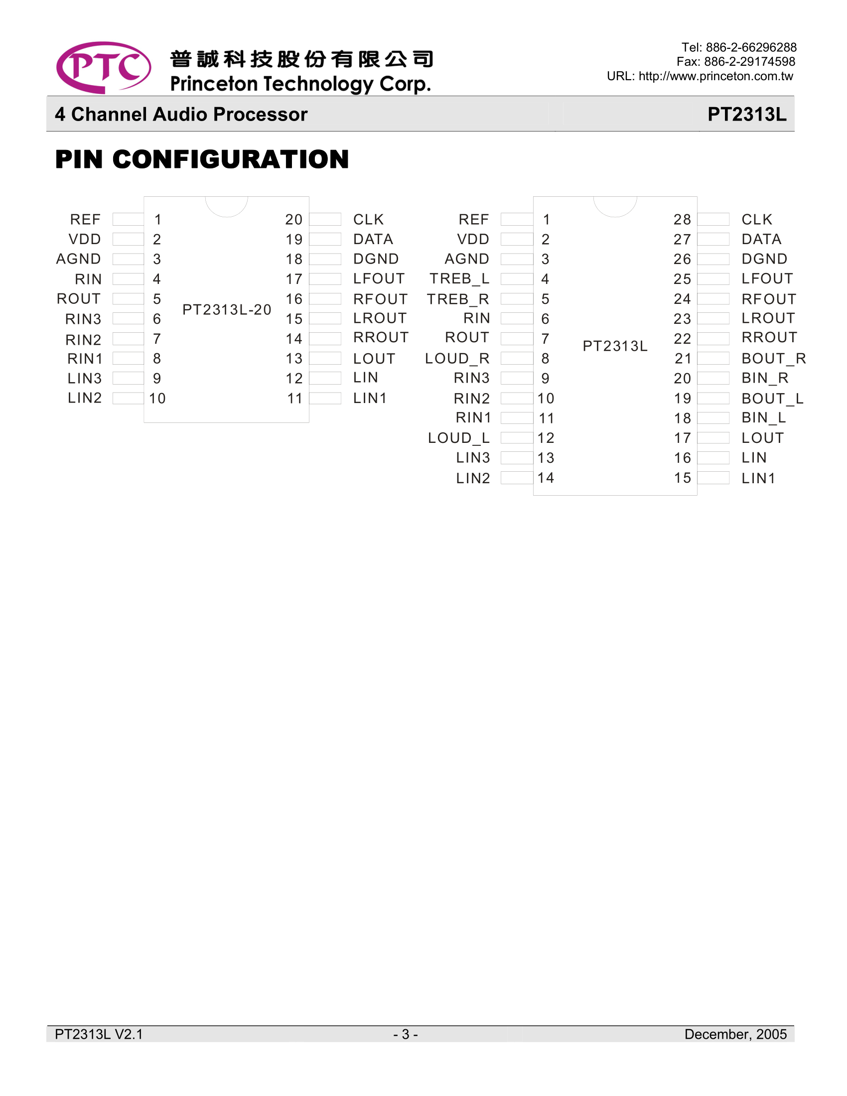
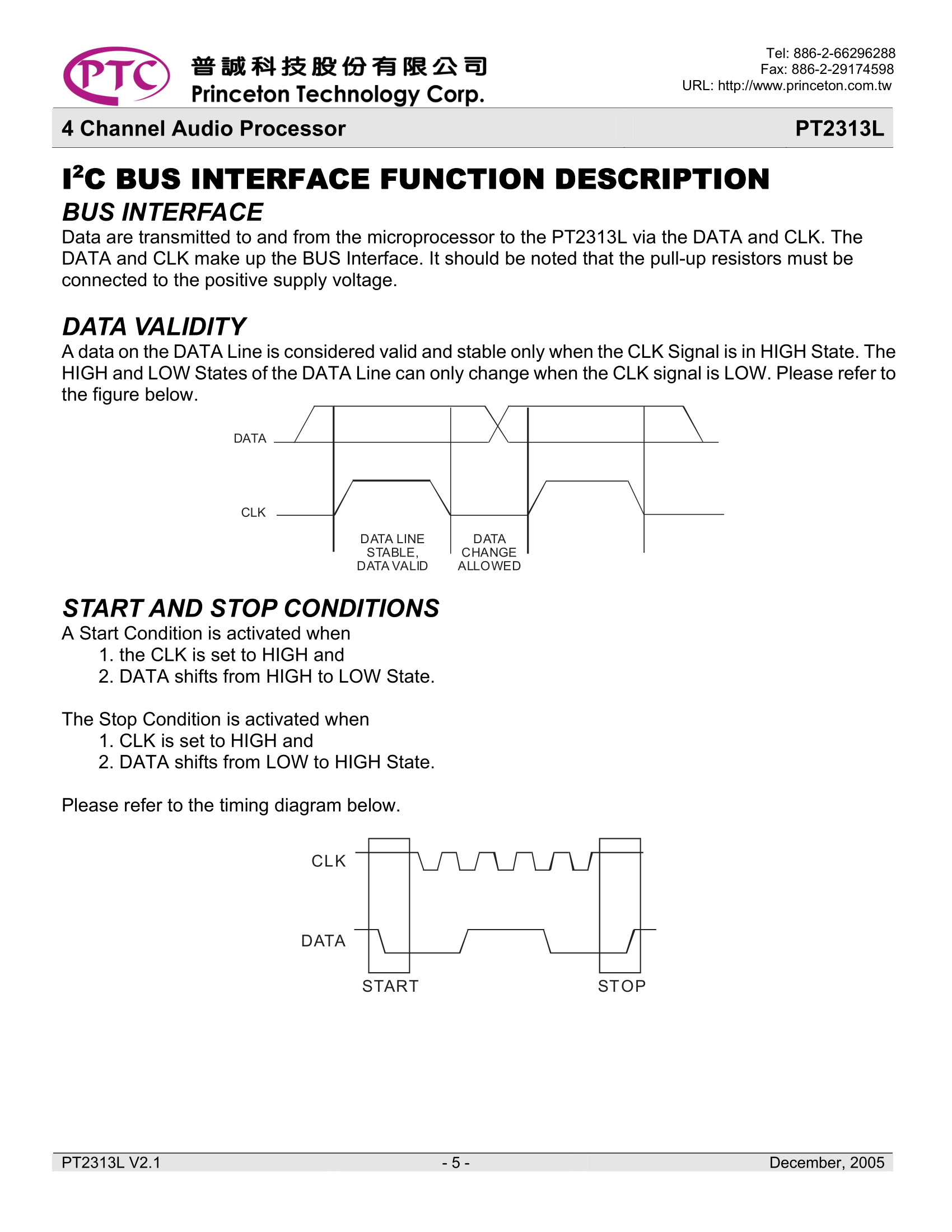
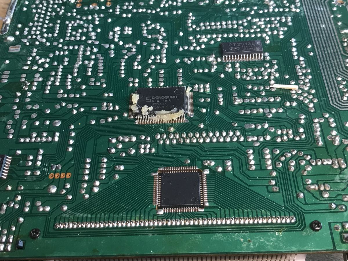
On the bottom of the PCB is still a separate processor responsible for audio, PT2313L:
It can be controlled via I2C interface.
The entire radio is controlled by SDONGSUNG NEW-791 JW541A.
Alas, without a datasheet, but you can guess from the tracks that it controls both LCD (via SPI, via PT6523) and audio (both CD player, amplifier, and radio).
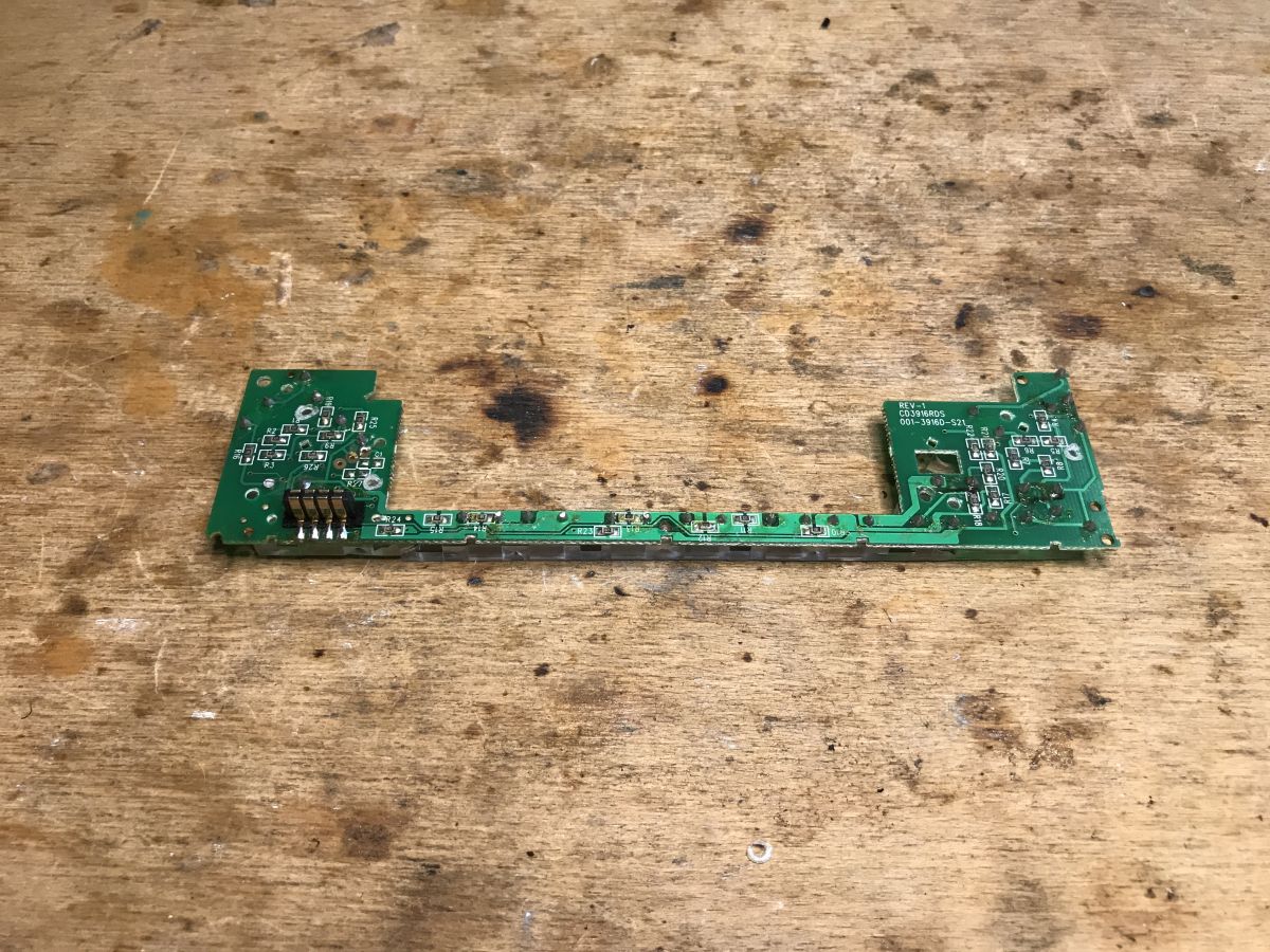
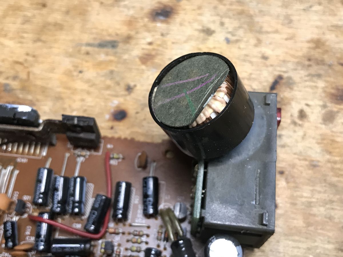
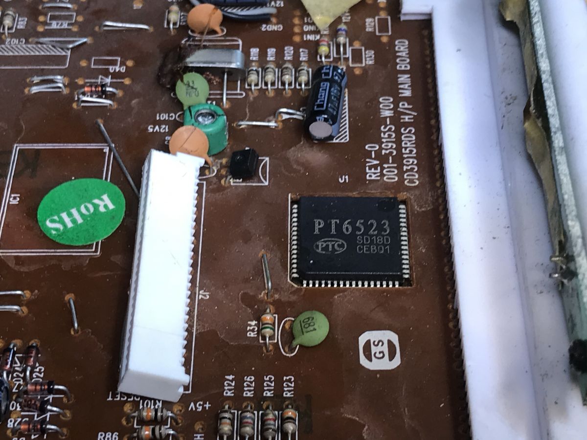
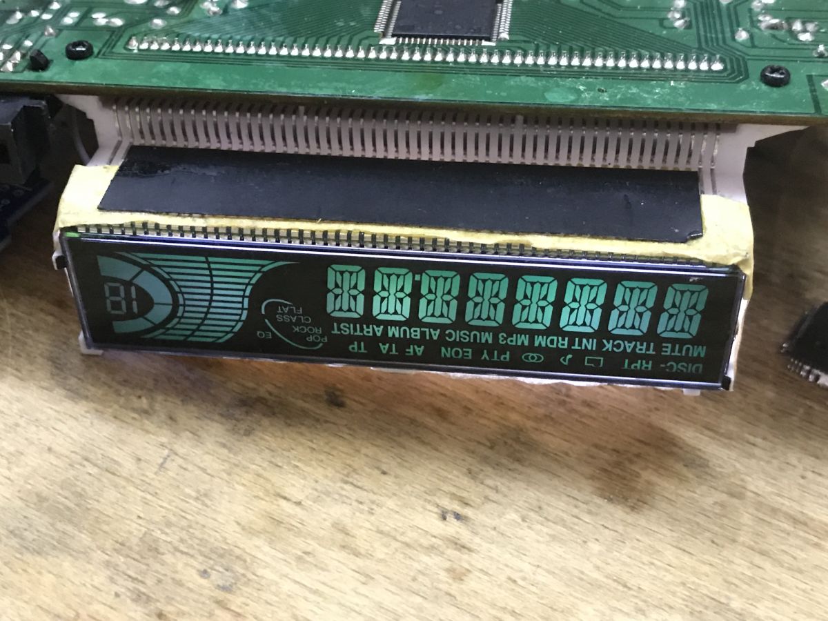
It's still worth noting the "mysterious" element at the power supply, which turns out to be a coil, probably against interference: Most interesting to me, however, is the LCD. It looks like it's supported by a universal controller, the kind I can drive from an Arduino:
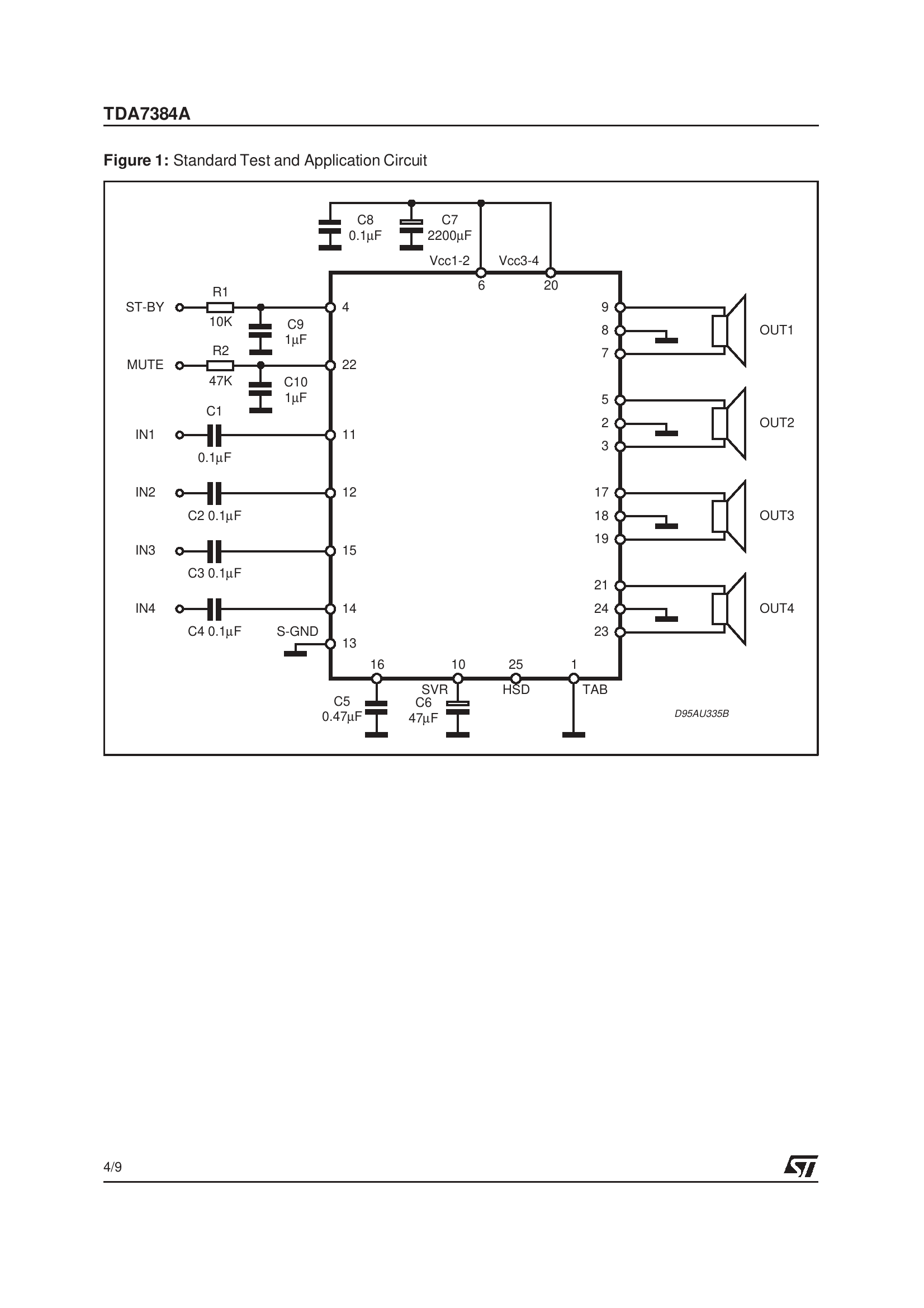
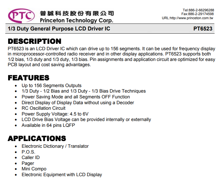
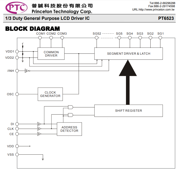
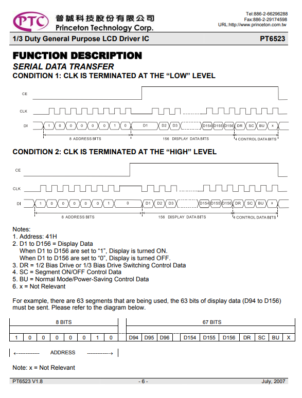
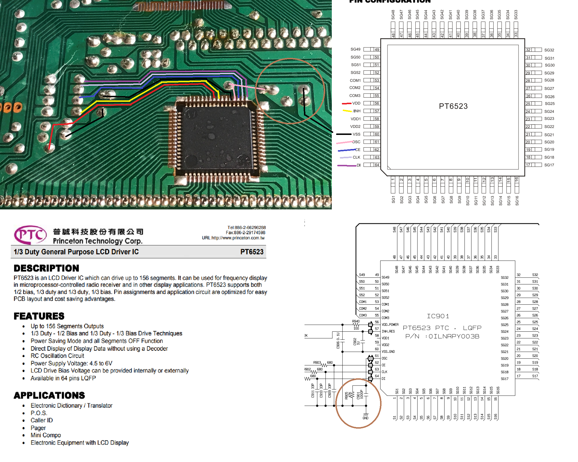
Very interesting assembly, what prompted them to mount it this way? Convenience of access to the LCD? All in all, the layout of the board is quite simple. The very name of the chip, PT6523, tells me this. After all, similar circuits are also used to control VFD displays, by the way, colleague @ArturAVS surely knows something about it, he published at one time a great series on VFDs and I think he even had his own controller realized on some PT . Here, of course, there's no VFD, it's an LCD, but it's still worth running. Let's look at the note: Factually, a general purpose controller, that's a good sign. Internal schematic, very simple, I can see the SPI interface: Okay, you can see everything as if on the palm of your hand. The entire serial interface (DI, CLK, CE and INH) goes to 4 resistors, which you can clearly see on the board. In addition, a path from the OSC goes the other way, to the RC resonator, which I marked with a circle. In addition to that, the power goes to the 16V electrolytic capacitor, which is right next to the resistors already mentioned. Pinout: PGIO roles. You can see that still INH controls the status of the display, so we have 4 lines to handle.... INH, CLK, DI, CE: The communication protocol is also described - everything as on a tray: It should be easy to control this. Still as an addendum, we can review the schematic of a finished device using this bone: On page 2 of the above schematic, you can see the PT6523 including the LCD and connection to the main controller. The SPI lines are connected through 680 ohm resistors and have 33pF capacitors to ground in addition. You can also see the RC resonator circuit and the LCD controller power supply along with decoupling.
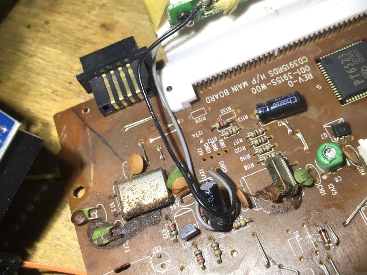
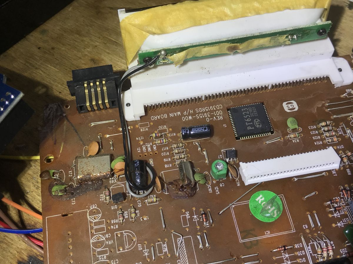
Resetting the LCD At the very beginning, I tried to fire up the PCB of this radio itself from the lab power supply with the current limitation active, but the display only flashed once on startup and then went out and gave no sign of life. Perhaps the main microcontroller was already detecting that something was missing. Therefore, I decided to remove it with hot air: Removed: Then I did an analysis of the connections, what is where on the PCB:
Additionally, I traced the 5V power supply from the LCD and the 12V power supply for the backlight (I checked the backlight voltage with a lab power supply, although 12V was printed on the PCB anyway):
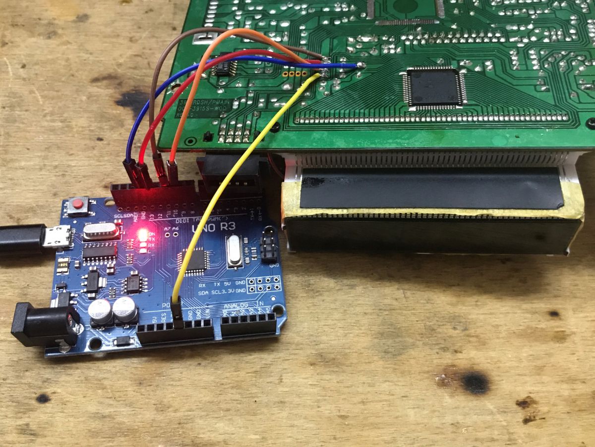
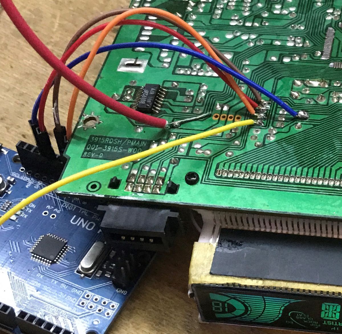
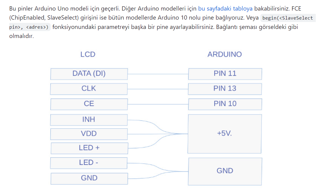
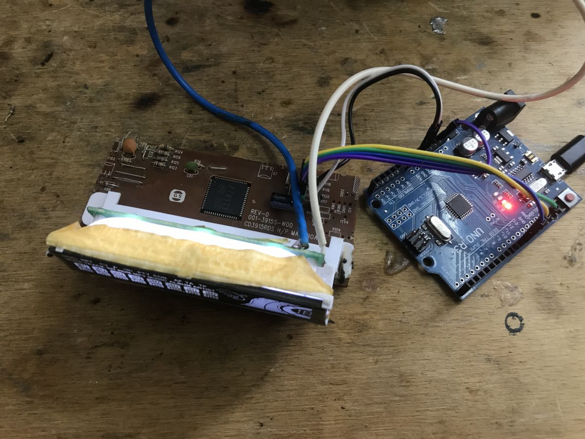
Then it was time to connect the Arduino. Here are the already soldered wires: This is what it looks like with the backlight attached: I initially thought I would be writing the dice support again from 0. This time, however, fate smiled. There was a ready-made one on Github. The communication itself wouldn't be a problem, but tracking down the roles of all the segments and writing them into some sort of enumeration would probably take a very long time. I used to do it on a display from a washing machine, the topic is in the table of contents of this thread. This is the repository I found: https://github.com/firatsoygul/PT6523 The repository has no description in English, but that's not a problem. At first glance everything matches, the pinology too: Well, in my case the backlight is on 12V, not 5V, but that's a detail. I launched the Arduino IDE and tried firing up an example:
Code: C / C++
Log in, to see the code
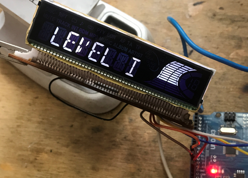
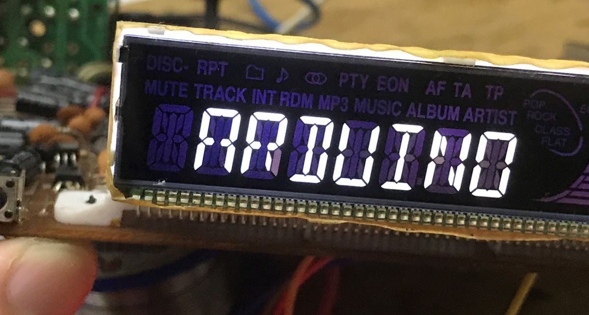
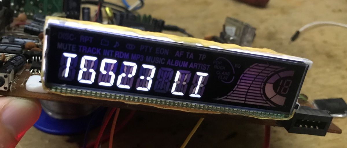
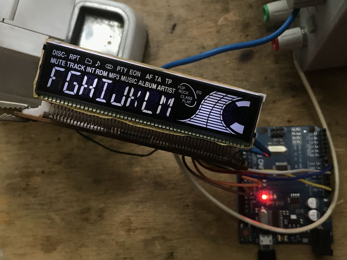
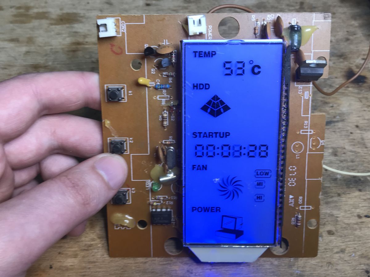
Success, and I think it's complete - even the segments aren't mixed up! Here is the Arduino caption: Further caption: Enthused by the success, I uploaded a full example - do the symbols match?
Code: C / C++
Log in, to see the code
All symbols work correctly. Shot in 10. The library used does everything for us and has correct symbol enumeration:
Code: C / C++
Log in, to see the code
. Result of play In the end, I was able to trim the PCB in such a way, that a relatively small and compact module with LCD came out:
When cutting the PCB with a small dremel tool, I also had to pay attention to where the tracks go and, for example. I had to Also add by hand jumpers between points that must be at ground potential, one jumper on the bottom of the PCB connects the ground from the RC oscillator circuit to GND PT6523. When cutting modules from whole devices in this way, you need to be aware of where all the paths are connected, so that there is no surprise later that the "freed" module does not work. In the photo you can barely see it, but all the wires are already connected to the goldpins, in addition, the power goldpin has a white plastic and the ground is black. The only thing left is the issue of 12V backlight - unfortunately, I did not have a good small step-up converter, so it will have to wait ... I wanted to get 12V from 5V with a small current capacity, but I need to buy a module for that. This is of course not the end of the fun, I'll be back to this display soon, and I have more interesting hardware to run in the queue. By the way, does anyone know what specific hardware this LCD is from? Some kind of UPS, central processing unit? Unfortunately its not likely to be used, too many symbols fitting under one particular display.
Summary This time a pretty cool display with SPI interface was recovered from scrap, which is even capable of displaying text, expanding the range of its potential DIY applications. Of course, we had to get a little lucky for this, because we got the LCD in a package with its controller PT6523, whose catalog note is available on the web and, what's more, there is a ready-made library for Arduino under it. Everything as on a platter, it would be much more difficult if the LCD was connected to some integrated processor performing multiple functions at the same time, then running it would rather not make sense. I also looked through the rest of the circuits, necessarily radio/audio, but I did not find any potential uses for them, what could be done with them in an interesting way. I intend to use the display in some future project, and in the meantime I end with the hope that maybe I inspired someone to do some DIY giving a second life to parts from scrap.
PS: As for this family of PT* chips, I already have a bit of VFD displays lined up on them.. .
About Author
p.kaczmarek2 wrote 14627 posts with
rating 12646 , helped 655 times.
Been with us since 2014 year.
RCAs were thus protected from adverse conditions in the car (moisture) and from accidental contact with, for example, +12V. In many radios I have seen this.
I had such a blue display a couple of years... [Read more]
zgierzman
11 Jun 2023 01:08
Theft prevention. Twenty years ago it was the norm for the panels to come off. When leaving the car, you took the front panel with you, and a potential thief was less tempted by such a radio - in order... [Read more]
Dydelmax
11 Jun 2023 11:37
As mentioned by a colleague RafGan this is a display that is part of the front panel of a desktop computer case. It can be used in a truncated way, e.g. as a display of data from a weather station... [Read more]
kotbury
11 Jun 2023 16:31
I'll also add that in case of theft - to the value of such a radio (even then meager) you had to add the value of the windshield (usually 3x more expensive than this radio), because in the past the children... [Read more]
ex-or
12 Jun 2023 13:04
Before the panels appeared, the entire radio was removed. [Read more]
tomus2k
14 Jun 2023 16:26
There was also available radios with a rotating panel what looked like someone took the panel - I have one and it plays until now. It had a wonderful display for those times e.g.
On allegro they want... [Read more]
If I hadn't read that it was LCD I would have thought it was some other kind of display. It reminded me too much of a cathode ray tube. Now I know what it is
Added after 2 [minutes]:
Wow this... [Read more]
kurnosek
19 Jun 2023 18:13
This blue display is probably from such a Tower PC case -> Tracer Xeno or similar. https://obrazki.elektroda.pl/2611356500_1687191202_thumb.jpg https://obrazki.elektroda.pl/2611356500_1687191202_thumb.jpg... [Read more]
FAQ
TL;DR: With 4 control lines and “everything as on a tray,” this FAQ shows Arduino DIY users how to reuse a Denver CAD-350 LCD by driving its PT6523 controller, using 5V logic and a separate 12V backlight supply. [#20612341]
Why it matters: A scrap car-radio display becomes a compact, text-capable Arduino module instead of e-waste.
Reuse target
Interface or supply
Reuse value
Main limitation
PT6523 LCD module
INH, CLK, DI, CE; 5V logic
Easy Arduino text and icons
Needs segment mapping
LCD backlight
12V
Makes display readable
Needs separate or step-up supply
PT2313L audio processor
I2C
Possible audio control
Less useful for display projects
K4S161622H SDRAM
Many parallel lines
Low DIY value
Too many lines to talk to
Key insight: The PT6523 made the recovered LCD practical because its datasheet and an Arduino library already matched the module. Without a separate LCD controller, reusing the custom glass would be much harder.
Quick Facts
Denver CAD-350 supports FM 87.5–108 MHz and includes a CD player, RCA outputs, and an ISO connector label. [#20612341]
The recovered LCD uses a PT6523 controller with 4 handled lines: INH, CLK, DI, and CE. [#20612341]
The LCD controller supply was traced as 5V, while the backlight was checked and marked as 12V on the PCB. [#20612341]
The audio amplifier identified in the radio is TDA7384, shown as a 4 × 35 W car-radio power amplifier. [#20612341]
A similar blue LCD was identified by forum users as a front-panel display from a desktop PC tower case, including Tracer Xeno or a similar case. [#20623416]
How do you run a Denver CAD-350 car radio LCD with a PT6523 controller from an Arduino?
Run it by isolating the PT6523 LCD module, wiring 5V power, ground, and the 4 serial control lines.
Trace INH, CLK, DI, and CE from PT6523 to accessible resistors or pads.
Connect Arduino control pins and keep PT6523 powered from 5V.
Use the PT6523 Arduino library and start with lcd.begin(10, 130).
The tested example scrolled “PT6523 LIBRARY FOR ARDUINO” successfully. The 12V backlight needs its own supply or a 5V-to-12V step-up module. [#20612341]
What is the PT6523 LCD controller and how does its serial interface work?
The PT6523 is a general-purpose LCD controller that drives segmented LCD glass through a simple serial interface. "PT6523 is an LCD controller that drives segmented display outputs from serial input data, using separate control lines for clocking, data, chip enable, and inhibition." The thread identifies DI, CLK, CE, and INH as the practical lines needed from Arduino. The author saw them routed through 4 resistors on the PCB. Its protocol was documented in the datasheet, making the display reusable without reverse-engineering every waveform. [#20612341]
Which Arduino library can control a PT6523 display recovered from a car radio?
The Arduino library used was the GitHub PT6523 library found at github.com/firatsoygul/PT6523. The author reported that its pinology matched the recovered Denver CAD-350 LCD. A minimal sketch used #include <PT6523.h>, created PT6523 lcd, then called lcd.begin(10, 130). The example also used lcd.speed(250) and lcd.sText("PT6523 LIBRARY FOR ARDUINO") for scrolling text. It correctly handled text, volume graphics, and many named symbols. [#20612341]
How do you identify the PT6523 pins for INH, CLK, DI, and CE on a salvaged radio PCB?
Identify them by following PT6523 traces from the chip pins to nearby series resistors and then to the removed main controller pads. The author found the serial interface lines “as if on the palm of your hand.” On this PCB, DI, CLK, CE, and INH passed through 4 visible resistors. The OSC line went separately to an RC resonator. Power went toward a nearby 16V electrolytic capacitor. This trace-based approach avoids guessing when the main microcontroller has no datasheet. [#20612341]
Why did the Denver CAD-350 display only flash once when powered from a lab supply?
The display flashed once because the original main microcontroller likely stopped driving it after detecting missing radio hardware. The author powered the radio PCB from a lab supply with current limiting enabled. The LCD lit briefly at startup, then went dark and stayed inactive. To bypass that failure mode, the main SDONGSUNG NEW-791 JW541A controller was removed with hot air. Arduino then drove the PT6523 directly through the serial lines. [#20612341]
How should the 5V PT6523 supply and 12V LCD backlight be wired when reusing this display module?
Wire the PT6523 logic and LCD controller to 5V, but power the backlight from 12V. The author traced the LCD 5V rail and separately checked the backlight voltage with a lab power supply. The PCB also had 12V printed for the backlight. The final module still needed a small step-up converter, because the author wanted 12V from a 5V source with low current capacity. Ground must remain common where the module requires it. [#20612341]
What precautions are needed when cutting a PCB to recover an LCD module from old electronics?
Cut only after tracing power, ground, oscillator, and signal paths across the whole module. The author trimmed the PCB with a small Dremel tool and kept the LCD section compact. A failure case appeared during cutting: some ground connections no longer remained continuous. One added jumper restored ground between the RC oscillator circuit and PT6523 GND. This matters because a freed module can fail silently if one required track was cut. [#20612341]
What do the PT6523 display symbols like MUTE, MP3, RPT, EQ, TP, TA, and AF mean on a car radio LCD?
They are named car-radio display segments controlled by the PT6523 library’s symbol enumeration. The tested enum included MUTE, MP3, RPT, EQ, TP, TA, AF, CD_ICON, DISC, TRACK, LOUD, ROCK, POP, FLAT, and CLAS. The author uploaded a full example and verified that all symbols worked correctly. "Display symbols are fixed LCD segments that show radio, audio, and playback states, each addressed by software through a named segment map."[#20612341]
What is the TDA7384 audio amplifier used for in the Denver CAD-350 radio?
The TDA7384 is the car-radio audio power amplifier used to drive the speaker outputs. The author identified it under the heatsink during the teardown. The thread shows it as a 4 × 35 W amplifier, which fits a multi-speaker car-radio output stage. The author considered it usable for DIY audio, but focused instead on microcontroller-friendly parts like the LCD controller. [#20612341]
What is the PT2313L audio processor and how is it controlled over I2C?
The PT2313L is an audio processor on the bottom of the Denver CAD-350 PCB, controlled through I2C. "PT2313L is an audio-processing IC that controls functions such as car-radio audio routing or adjustment, using an I2C interface for digital commands." The author identified it as a separate audio-related processor, distinct from the PT6523 LCD controller. It had potential reuse value, but the thread did not develop an Arduino audio-control example for it. [#20612341]
What are LA1140 and LA3370 chips used for in an FM car radio?
LA1140 handles FM intermediate-frequency processing, while LA3370 handles FM stereo multiplex demodulation. The author found LA1140 beside the FM head and described it as the IF handling circuit. LA3370 sat near the PCB edge under capacitors and was identified as a PLL FM Multiplex Stereo Demodulator. Together, they belong to the radio-reception path, not the LCD reuse path. [#20612341]
Why did older car radios have removable front panels?
Older car radios used removable front panels as theft prevention. A user explained that around 20 years before the 2023 thread, removable panels were normal. Drivers took the panel away when leaving the car. A thief then needed the matching original panel to sell or use the radio. The mechanism often used one button, and the panel popped into the user’s hand. Cases like eyeglass cases protected the loose panel. [#20612554]
What was the purpose of protected RCA connectors on the back of some car radios?
Protected RCA connectors reduced exposure to moisture and accidental contact with +12V inside a car. A forum reply states that this protection appeared in many radios. The concern was practical: rear audio connectors sit near vehicle wiring and damp conditions. Shielding or recessing them reduced electrical accidents and environmental damage. In the Denver CAD-350, the rear connectors were identified as RCA outputs during the teardown. [#20612507]
PT6523 LCD vs VFD display controllers — which is easier to reuse with Arduino for DIY projects?
The PT6523 LCD was easier in this case because its datasheet and Arduino library already matched the module. The author noted that similar PT-family chips also control VFD displays, and another forum member had made PT-based VFD work. But this recovered LCD had a ready Arduino path: serial lines, known 5V logic, mapped symbols, and working examples. A custom LCD tied only to a multifunction processor would be much harder to reuse. [#20612341]
Where did the blue LCD with many PC-related icons likely come from, such as a Tracer Xeno tower case or similar computer case display?
The blue LCD likely came from a desktop PC tower case front panel, such as Tracer Xeno or a similar case. Multiple users recognized it as a computer-case display. One described a factory-installed case panel that showed standard parameters and changed fan speed. Another identified it as a display from a Tower PC case and named Tracer Xeno or similar. Its many fixed icons limit full reuse, but it can still show weather-station data or a clock. [#20623416]

Comments
RCAs were thus protected from adverse conditions in the car (moisture) and from accidental contact with, for example, +12V. In many radios I have seen this. I had such a blue display a couple of years... [Read more]
Theft prevention. Twenty years ago it was the norm for the panels to come off. When leaving the car, you took the front panel with you, and a potential thief was less tempted by such a radio - in order... [Read more]
As mentioned by a colleague RafGan this is a display that is part of the front panel of a desktop computer case. It can be used in a truncated way, e.g. as a display of data from a weather station... [Read more]
I'll also add that in case of theft - to the value of such a radio (even then meager) you had to add the value of the windshield (usually 3x more expensive than this radio), because in the past the children... [Read more]
Before the panels appeared, the entire radio was removed. [Read more]
There was also available radios with a rotating panel what looked like someone took the panel - I have one and it plays until now. It had a wonderful display for those times e.g. On allegro they want... [Read more]
and put under the seat :] [Read more]
If I hadn't read that it was LCD I would have thought it was some other kind of display. It reminded me too much of a cathode ray tube. Now I know what it is Added after 2 [minutes]: Wow this... [Read more]
This blue display is probably from such a Tower PC case -> Tracer Xeno or similar. https://obrazki.elektroda.pl/2611356500_1687191202_thumb.jpg https://obrazki.elektroda.pl/2611356500_1687191202_thumb.jpg... [Read more]